1
BWC Tilt-up Tower & BWC EXCEL1
INSTALLATION MANUAL
TableofContents
Safety..............................................................................................................................2
1) Components...............................................................................................................4
2) Anchors & Base Plate................................................................................................6
3) Tower Assembly.......................................................................................................12
4) Initial Tower Raising.................................................................................................19
5) Lowering the Tower..................................................................................................21
6) Installing the EXCEL1 Wind Turbine........................................................................22
7) Final Tower Raising .................................................................................................29
8) Misc. Reference Material .........................................................................................31
9) Tilt Tower Packing Lists...........................................................................................37
TableofFigures
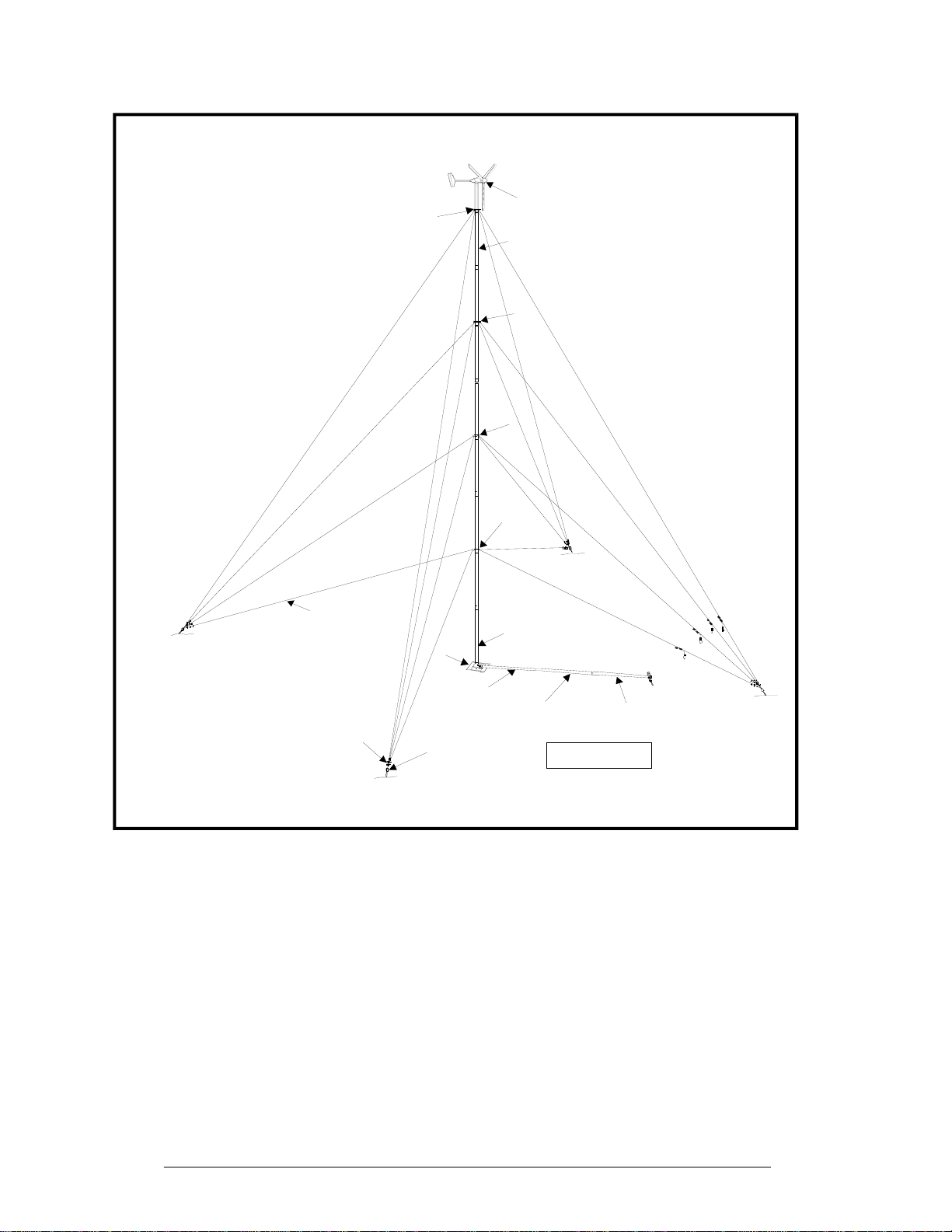
Figure 1: Major Tower Components...............................................................................5
Figure 2: Anchor Layout.................................................................................................7
Figure 3: Base Plate Assembly....................................................................................10
Figure 4: Anchor Installation.........................................................................................11
Figure 5: Guy Wire Attachment....................................................................................15
Figure 6: Gin-pole Safety Wire Assembly.....................................................................16
Figure 7: Tower Tilt-up Sequence................................................................................19
Figure 8: Major Components of the EXCEL 1..............................................................22
Figure 9: EXCEL 1 Wiring Schematics.........................................................................23
Figure 10: Turbine Mounting........................................................................................25
Figure 11: Blade and Spinner Fasteners......................................................................26
Figure 12: Nut Tightening Order...................................................................................27
Figure 13: Tail Fin Attachment.....................................................................................27
Figure 14: Tail Boom Attachment.................................................................................28
Figure 15: Guy Wire Transfer Sequence......................................................................29
Figure 16: Concrete Anchors .......................................................................................33
TableofTables
Table 1: Pull-up Force and Cable Travel......................................................................17
Table 2: Recommended Wire Sizes for the EXCEL1 24V............................................24
Table 3: Soil Classifications .........................................................................................32