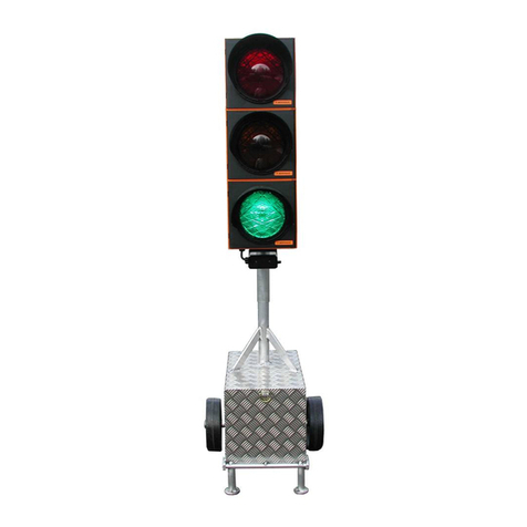
berghaus MPB 4400 User manual

Operating Instructions
Construction Site Traffic
Signal System MPB 4400
GB

General explanation of building site signalling equipment
Signal safety
The German regulations of VDE, TL-LSA 97 and RiLSA describe among others the
use of portable construction site traffic signal systems.
The above regulations stipulate that no signal safety feature as per RiLSA and VDE
0832 is necessary e.g. for construction sites with alternating one-way traffic control
and a clearance speed of up to 30 km/h, insofar as the corresponding authorities have
not imposed any stricter conditions or requirements.
All other construction site traffic signal systems used for controlling traffic at
T-junctions, crossroads or pedestrian crossings must be equipped with a signal safety
feature as per RiLSAand VDE 0832, and fulfil TL-LSA97.
This safety feature requires a feedback message which can be transmitted by radio or
cable. Radio-controlled traffic signals use top-quality radio modules which have been
given an approval number by the German Federal NetworkAgency for electricity, gas,
telecommunications, postal and railway markets (formerly RegTP).
Peter Berghaus GmbH produces and supplies construction site traffic signal
systems and signal safety feature.with without

TABLE OF CONTENTS
I. Presentation of the and Manual Device ModelsMPB 4400
Pages 1 to 2
II. Programming / Re-programming
Pages 3 to 58
1. One-Way Alternating-Direction Traffic
Pages 3 to 6
2. One-Way Alternating-Direction Traffic with Special Options
(see Chapters III + IV)
Pages 7 to 12
3. One-Way Alternating-Direction Traffic that is Traffic-Flow
Dependent
Pages 13 to 15
4. One-Way Alternating-Direction Traffic that is Traffic-Flow
Dependent, with Special Options (see Chapters III + IV)
Pages 16 to 21
5. Intersection Traffic
Pages 22 to 26
6. Intersection Traffic with Special Options
(see Chapters III + IV)
Pages 27 to 33
7. Intersection Traffic that is Traffic-Flow Dependent
Pages 34 to 38
8. Intersection Traffic that is Traffic-Flow Dependent
with Special Options (see Chapters III + IV)
Pages 39 to 46
9. Reprogramming or changing the time settings of a radio/cable
traffic signal which has already been commissioned
Pages 46 to 47
10. Reading out data with the handbox during on-going operation
Page 48

III. Special Options with Quartz Operation (Night-time Mode)
Page 49
IV. Special Options with Radio and Cable Operation
(Night-time Mode, Day Programmes, Interval matrix ,
Forced Circulation and Data Transmission via PC)
Pages 50 to 53
V. Auxiliary Functions (Manual Operation, Setting the Time
of Day, Selecting Programmes, Version Display and Error
Acknowledgement)
Pages 54 to 64
VI. Control Device / Error Messages for Control Device
Pages 65 to 69
VII. Manual Device / Error Messages for Manual Device
Pages 70 to 72
VIII. Accessories
Page 73
IX. Technical Data
Page 74
X. Radar Detector
Pages 75 to 76
XI. Spare Parts List
Pages 77 to 78
XII. Warranty
Page 80

I. Introduction
The is the universal signal equipment for all trafficMPB 4400
situations subject to traffic light control, including installations for the
following traffic patterns: one-way alternating-direction; junction-
merging and pedestrian installations; also for intersection signal
installations with 12 groups and a maximum of 24 signal heads with
control units that are 100% identical in construction.
The installation can be supplied as orQuartz, Cable Quartz, Cable-
Radio Equipment.
In cable as well as in radio mode, the equipment possesses all
monitor features specified by RiLSA:
- Red Light Monitoring
- Green-Green Prevention
- Green Status
- Interval Monitoring (required acc. to RiLSA,
Appendix G.3)
- Watch Dog (computer monitoring)
All data such as signal time plans and malfunctions with date can be
printed out on a printer.
The following operating modes are possible:
1. Fixed time programme as well as fixed time programme with up to
4 daytime programmes
2. Traffic-flow-dependent mode as well as traffic-flow-dependent
mode with up to 4 daytime programmes
3. Traffic-flow-dependent mode with green on demand with up to 4
daytime programmes
4. Flashing and darkness programme
Up to 4 start times with different blocks of days can be entered for all
programmes.
1

MANUALDEVICE MODELS
Switching the manual device off and on
Before you can set the manual device into operation, the batteries
(4* Mignon AA) that are supplied with it must first be installed. To do
this, open the battery chamber on the rear side of the device and insert
the batteries (be sure the polarity is correct!).To switch the device on,
briefly press the "ON" key.
The manual device will then display the manual device model. You can
switch off the manual device by holding the #2 key pressed down for ca.
5 seconds.
The display shows the following, depending upon manual device
model:
Chapter II Number 1 + 2
Chapter II Number 3 + 4
Chapter II Number 5 + 6
Chapter II Number 7 + 8
You have different programming possibilities available to you,
depending upon manual device model.These are explained in detail in
the Chapters listed next to the manual device displays.
**M P B 4400**
One Way Traffic
* M P B 4400 VA*
One Way Traffic
**M P B 4400**
Cross-roads
* M P B 4400 VA*
Cross-roads
2

1. Input for One-WayAlternating-Direction Traffic
Without traffic-flow dependency and without special
options
You can programme one-way alternating-direction
traffic with this manual device.
Before programming the signal equipment, you should make sure that
the time of day and date are set correctly in the manual device. You can
determine this by switching on the manual device. After approximately
10 seconds, the current time of day and date are presented automatically
in the display. If the information shown is not correct, then reset the
numbers as described in the "Auxiliary Functions" Chapter on page 53
of this manual. Switch further using key #4 until the manual device tells
you to program the traffic light. In doing so, the manual device requests
a variety of entries. You can alter the date by using the keys #1 and #3.
The number that is currently valid will be flashing. If you hold the key
pressed down for a longer time, then the numbers change more quickly.
The display shows:
Select with the keys #1 and #3 the desired operating mode, for example
"Quartz" for quartz operation.
With key #4 you then move further to the point for entering the
Please select:
Quartz Radio Cable
Site length:
>-< 50 m >+<
**M P B 4400**
One Way Traffic
3

Here you can alter the length of the roadworks site using the keys #1
and #3.
Once the value is set, proceed further with key #4.
The current speed will be flashing. Set the required speed for within the
roadworks site.
Then press key #4 again. The following will appear:
These two times have been calculated by the manual device.
For safety reasons, the displayed periods for traffic-clearing must be
considered irreducible minimums. It is however possible to increase the
times using key #3--to different extents, if desired: Thus, at a road
works site on a mountain, for example, the ascending traffic can be
allowed a longer traffic-clearing period. Traffic-clearing period #1 ends
when traffic light #2 has finished its green signal.
Press key #4 once again and follow the display in the manual device:
The displayed value in the line in which the arrow is blinking can be
altered using keys #1 and #3. With key #4, one moves one line down,
and can then alter the time setting there.
At this point, all the entries in the manual device are completed.
Press key #4 once again. The display shows:
Clr.time 1 => 10s
Clr.time 2 = 10s
Select: (km/h)
10 40 50 7030
Grn.time 1 => 5s
Grn.time 2 = 5s
Making
signalplan
4

After the formulation of the signal plan, the display switches to the
following message:
Plug the device into the first traffic light (traffic light #1). Switch the
traffic light on. The following must be visible in the traffic light display:
a.) with Quartz Operation
Press key #4 on the manual device. The data from the hand device will
be transmitted to the first traffic light (traffic light #1).
Manual device: Control device:
The second traffic light must still now be programmed. Plug the manual
device into the second traffic light and switch the traffic light on,
waiting then a moment until the following is displayed in the control
device:
Now press key #4 on the plugged-in manual device. The data will be
transmitted into the second traffic light (traffic light #2). The entire
equipment (traffic light #1 and traffic light #2) synchronise themselves
automatically and start the programme flow.
Put box into
Unit 1 >4<
12,8 V Light ??
No data !
12,8 V Light ??
No data !
Sending to light
Datablock: 159 /
12,8 V Light 1
Receiving /
Transmission
>> OK <<
Transmission
>> OK <<
1 light correct
programmed
5

b.) with Radio Cable Operationor without Special Options
The selection proceeds as described in Item 1.2. You select however,
depending upon the connection mode, not quartz but either radio or
cable instead. For this you need programme only one traffic light with
the manual device. Once you have ,linked the equipment with cables
switch on .one traffic light
Once it is programmed, this will be known as traffic light #1.
The following must be displayed in the control device:
The cable linkage is not required with a radio installation. Programme
the first traffic light (traffic light #1) with the manual device, for which
you plug the manual device into the traffic light and press key #4 after
the display calls for it. The two displays then show the following:
Manual device: Control device:
After switching on traffic light #2, the programme is transmitted by
radio or cable to the other traffic light (traffic light #2) and the
installation starts up completely automatically.
Warning: In the event of a data loss at traffic light #1 or #2 (through
activation of the on/off switch), the entire installation must be re-
programmed in the case of a .radio signal installation
Manual Options: (Flashing, Lights Off, All-Red and Programme
Selection) The procedural methods with manual options can be found in
Chapter V "Auxiliary Functions", on page 53 of this manual.
12,8 V Light 1
Light 2 missing !
12,8 V Light ??
No data !
6
Sending to light
Datablock: 159 /
12,8 V Light 1
Receiving /
Transmission
>> OK <<
Transmission
>> OK <<
1 light correct
programmed

2. Input for One-Way Alternating-Direction Traffic
Radio or cable operation without traffic-flow dependency,
but with special options such as Nighttime Mode, Day
Programmes, Interval matrix, Forced Circulation and Data
Transmission via PC
With this manual device you can programme one-way alternating-
direction traffic without traffic-flow dependency, although with
special options. Directions for setting the special options can be
found starting on page 49 of this manual.
Before programming the signal equipment, you should make sure that
the time of day and date are set correctly in the manual device. You can
determine this by switching on the manual device. After approximately
10 seconds, the current time of day and date are presented automatically
in the display. If the information shown is not correct, then reset the
numbers as described in the "Auxiliary Functions" Chapter on page 53
of this manual.
Switch further using key #4 until the manual device tells you to
programme the traffic light. In doing so, the manual device requests a
variety of entries.You can alter the date by using the keys #1 and #3. The
number that is currently valid will be flashing.
If you hold the key pressed down for a longer time, then the numbers
change more quickly.
The display shows:
Select with the keys #1 and #3 the desired operating mode, for example
"Cable" or "Radio" (the only special option available with quartz
operation is Night-time Mode).
With key #4 you then move further to the point of entering the
Please select:
Quartz Radio Cable
7
**M P B 4400**
One Way Traffic

Here you can alter the length of the roadworks site using the keys #1
and #3.
Once the value is set, proceed further with key #4.
The current speed will be flashing. Set the required speed for within the
roadworks site.
Then press key #4. The following will appear:
These two times have been calculated by the manual device. For safety
reasons, the displayed periods for traffic-clearing must be considered
irreducible minimums. It is however possible to increase the times
using key #3--to different extents, if desired: Thus, at a road works site
on a mountain, for example, the ascending traffic can be allowed a
longer traffic-clearing period. Traffic-clearing period #1 ends when
traffic light #2 has finished its "Green".
Press key #4 once again and follow the display in the manual device. If
you have selected Daytime Programme as a special option, then the
following display appears. The method used to activate the special
options is described in the annex under "Special Options".
Here you are called upon to enter the 1st Daytime Programme:
The displayed value in the line in which the arrow is blinking can be
altered using keys #1 and #3. With key #4, one moves one line down,
and can then alter the time setting there.
Input >4<
Dayprogram 1
Site length:
>-< 50 m >+<
Select: (km/h)
10 40 50 7030
Clr.time 1 => 10s
Clr.time 2 = 10s
Grn.time 1 => 5s
Grn.time 2 = 5s
8

When you are carrying out a re-programming, you have the opportunity
of deleting old switch points that may be left over from a previous
programming. For this, select "Yes", and confirm your choice with key
#4.
Once you have completed these entries, the manual device will ask you
for 4 switch points for the entered Daytime Programme #1. This means
that once you have entered a Daytime Programme, you can have it start
itself as many as four times a day, at the different times that you select:
00:00 means in this connection no input. For midnight, you must enter
24:00
After entering the starting time, you will be called upon to specify the
days on which the programme is to be used.
If you have selected two or more Daytime Programmes, then you will
now be called upon to enter these as described above (Enter Daytime
Programme #2).
After this entry, you have the opportunity of determining the Night-time
Mode, if you have activated it as described in the annex under "Special
Options".
If you select "Yes" here, then you will be called upon to programme the
Night-time Mode:
Here you are asked to select 4 switch points for the Night-time Mode.
This means you can have the Night-time Mode start itself as many as
four times a day, at the different times that you select:
Switchp. clear ?
yes no
Switchp. 1 Pro 1
Start:>06:00 Uhr
Select Days
all Mo-Fr Sa-So
Nightmode:
yes no
Input >4<
Nightprog. darkl
9

00:00 means in this connection no input. For midnight, you must
therefore enter 24:00
After entering the starting time, you will be called upon to specify the
days on which the programme is to be used.
Afterwards, you have the opportunity to set the Night-time Mode for
Flashing:
Here you are asked to select 4 switch points for the Night-time Mode.
This means you can have the Night-time Mode start itself as many as
four times a day, at the different times that you select:
00:00 means in this connection no input. For midnight, you must
therefore enter 24:00
After entering the starting time, you will be called upon to specify the
days on which the programme is to be used.
After you have selected the days, (press key #4), the following display
appears, if you have set the Interval Matrix under Special Options to
"Yes":
Using the keys #1 and #3, you can select whether or not you wish to
activate the Interval Matrix.
The previous setting flashes. The Interval Matrix is an additional
control function for monitoring the minimum traffic-clearing periods.
Switchp. 1 off
Start:>23:00 Uhr
Switchp. 1 flash
Start:>22:00 Uhr
Meantimes
yes no
Select Days
all Mo-Fr Sa-So
Input >4<
Nightprog. flash
Select Days
all Mo-Fr Sa-So
10

The Interval Time is the period of time between the end of the green
phase (e.g. of traffic light #1) and the beginning of the clear signal
(green) for a coming traffic flow that intersects or merges (in this case
traffic light #2, as one-way alternating-direction traffic operation was
selected). Traffic-clearing time computation proceeds automatically
for one-way alternating-direction traffic.
After selection of the Interval Matrix, the following display appears:
For one-way alternating-direction traffic, the intervals are adopted
automatically from the traffic-clearing times, and can no longer be
altered. This serves for adoption of the minimum traffic-clearing times.
Confirm this with key #>4<. Now the display appears for setting the
interval from traffic light #2 to traffic light #1 (this, too, will be
automatically adopted):
At this point, all the entries in the manual device are completed. Press
key #4 once again. The display shows:
After the formulation of the signal plan, the display switches to the
following message:
Switch on a traffic light (which then automatically becomes traffic light
#1). The following must be visible in the traffic light display:
Plug the device into the first traffic light (traffic light #1). Press key #4
on the manual device. The data from the hand device will be transmitted
to the first traffic light (traffic light #1).
from 1 => 2
10 sec
from 2 => 1
10 sec
Making
signalplan
Put box into
Unit 1 >4<
12,8 V Light ??
No data !
11

Manual device Control device::
After switching on traffic light #2, the programme is transmitted by
radio or cable to the other traffic light (traffic light #2) and the
installation starts up completely automatically.
Warning: In the event of a data loss at traffic light #1 or #2 (through
activation of the on/off switch), the entire installation must be re-
programmed in the case of a .radio signal installation
Manual Options:
(Flashing, Lights Off,All-Red and Programme Selection)
The procedural methods with manual options can be found in Chapter V
"Auxiliary Functions", on page 53 of this manual.
12
12,8 V Light 1
Light 2 missing !
Sending to light
Datablock: 159 /
12,8 V Light 1
Receiving /
Transmission
>> OK <<
Transmission
>> OK <<
1 light correct
programmed

3. Input for One-Way Alternating-Direction Traffic
With traffic-flow dependency but without special options
With this manual device you can programme one-way alternating-
direction traffic with traffic-flow dependency, although without
special options.
Before programming the signal equipment, you should make sure that
the time of day and date are set correctly in the manual device. You can
determine this by switching on the manual device.
After approximately 10 seconds, the current time of day and date are
presented automatically in the display. If the information shown is not
correct, then reset the numbers as described in the "Auxiliary
Functions" Chapter on page 53 of this manual. Switch further using key
#4 until the manual device tells you to programme the traffic light. In
doing so, the manual device requests a variety of entries. You can alter
the date by using the keys #1 and #3. The number that is currently valid
will be flashing.
If you hold the key pressed down for a longer time, then the numbers
change more quickly.
The display shows:
Select with the keys #1 and #3 the desired operating mode, for example
"Cable" or "Radio". If "Quartz" is selected, then traffic-flowno
dependency is possible.
With key #4 you then move further to the point of entering the traffic-
flow dependency:
Traffic related:
yes no
Please select:
Quartz Radio Cable
13
**M P B 4400 VA**
One Way Traffic

Set the traffic-flow dependency to "Yes" ("Yes" flashes) and confirm the
selection with key #4. The manual device display shows the following:
Here you can alter the length of the roadworks site using the keys #1
and #3. Once the value is set, proceed further with key #4.
The current speed will be flashing. Set the required speed for within the
roadworks site. Then press key #4 again. The following will appear:
These two times have been calculated by the manual device. For safety
reasons, the displayed periods for traffic-clearing must be considered
irreducible minimums. It is however possible to increase the times
using key #3 - to different extents, if desired: Thus, at a road works site
on a mountain, for example, the ascending traffic can be allowed a
longer traffic-clearing period. Traffic-clearing period #1 ends when
traffic light #2 has finished its green signal.
Press key #4 once again and follow the display in the manual device:
Now one can set a minimum and a maximum green time for signal
group #1. Continue with key #4.
Now the same entries are made as above, this time for signal group #2.
At this point, all the entries in the manual device are completed. Press
key #4 once again. The display shows:
After the formulation of the signal plan, the display switches to the
Grn2 min => 10s
Grn2 max = 25s
Grn1 min => 10s
Grn1 max = 35s
Site length:
>-< 50 m >+<
Select: (km/h)
10 40 50 7030
Clr.time 1 => 10s
Clr.time 2 = 10s
Making
signalplan
14

following message:
Switch on a traffic light (which then automatically becomes traffic
light #1). The following must be visible in the traffic light display:
Plug the device into the first traffic light (traffic light #1). Press key #4
on the manual device. The data from the hand device will be transmitted
to the first traffic light (traffic light #1).
Manual device: Control device:
After switching on traffic light #2, the programme is transmitted by
radio or cable to the other traffic light (traffic light #2) and the
installation starts up completely automatically.
Warning: In the event of a data loss at traffic light #1 or #2 (through
activation of the on/off switch), the entire installation must be re-
programmed in the case of a .radio signal installation
Manual Options:
(Flashing, Lights Off,All-Red and Programme Selection)
The procedural methods with manual options can be found in Chapter V
"Auxiliary Functions", on page 53 of this manual.
Put box into
Unit 1 >4<
12,8 V Light ??
No data !
15
12,8 V Light 1
Light 2 missing !
Sending to light
Datablock: 159 /
12,8 V Light 1
Receiving /
Transmission
>> OK <<
Transmission
>> OK <<
1 light correct
programmed

4. Input for One-Way Alternating-Direction Traffic
Radio or cable operation with traffic-flow dependency and
with special options such as Nighttime Mode, Day Pro-
gramme, Interval matrix, Forced Circulation and Data
Transmission via PC
With this manual device you can programme one-way alternating-
direction traffic with traffic-flow dependency and with special
options. Directions for setting the special options can be found
starting on page 49 of this manual.
Before programming the signal equipment, you should make sure that
the time of day and date are set correctly in the manual device. You can
determine this by switching on the manual device. After approximately
10 seconds, the current time of day and date are presented automatically
in the display. If the information shown is not correct, then reset the
numbers as described in the "Auxiliary Functions" Chapter on page 53
of this manual.
Switch further using key #4 until the manual device tells you to
programme the traffic light. In doing so, the manual device requests a
variety of entries.You can alter the date by using the keys #1 and #3. The
number that is currently valid will be flashing.
If you hold the key pressed down for a longer time, then the numbers
change more quickly.
The display shows:
Select with the keys #1 and #3 the desired operating mode, for example
"Cable" or "Radio".
If "Quartz Operation“ is selected, neither traffic flow dependency nor
special options such as Daytime Programme and Time Interval are
Please select:
Quartz Radio Cable
16
**M P B 4400 VA**
One Way Traffic
Table of contents
Other berghaus Construction Equipment manuals
Popular Construction Equipment manuals by other brands

Case
Case CRAWLER DOZER 650L TIER3 Service manual
PROAIM
PROAIM CINEMA Series instruction manual

AIRLESSCO
AIRLESSCO Sure Stripe 4550 Operation - repair - parts

Kessel
Kessel Aqualift S LW 1000 installation instructions

PANDROL
PANDROL CD100 B User and maintenance manual
Altrad
Altrad BELLE MINIMIX 150E+ Operator's manual
