AIRLESSCO Sure Stripe 4550 Use and care manual

3A2702A
EN
Operation, Repair, Parts
Airless Paint
Line Striper
For the application of line striping materials. For professional use only. For outdoor use
only. Not for use in hazardous locations or explosive atmospheres.
Sure Stripe 4550, Sure Stripe 6050.
3300 psi (22.8 MPa, 228 bar) Maximum Working Pressure
See page 48 for model information, including maximum working pressure and approvals.
Important Safety Instructions
Read all warnings and instructions in this manual, related manuals, and on the
equipment. Be familiar with the controls and the proper usage of the equipment.
Save these instructions.
Related Manuals - 312363 - 500 Gun
- 3A0479- 009 Gun
Sure Stripe Model 6050
Sure Stripe Model 4550

Contents
2 3A2702A
Contents
Models . . . . . . . . . . . . . . . . . . . . . . . . . . . . . . . . . . . . . . . . . . . . . . . . . . . . . . . . . . . . . . . 3
Warnings . . . . . . . . . . . . . . . . . . . . . . . . . . . . . . . . . . . . . . . . . . . . . . . . . . . . . . . . . . . . . 4
Uni-Tip Selection . . . . . . . . . . . . . . . . . . . . . . . . . . . . . . . . . . . . . . . . . . . . . . . . . . . . . . . 7
Component Identification . . . . . . . . . . . . . . . . . . . . . . . . . . . . . . . . . . . . . . . . . . . . . . . . 8
Operation . . . . . . . . . . . . . . . . . . . . . . . . . . . . . . . . . . . . . . . . . . . . . . . . . . . . . . . . . . . . . 9
Setup . . . . . . . . . . . . . . . . . . . . . . . . . . . . . . . . . . . . . . . . . . . . . . . . . . . . . . . . . . . . . 9
Pressure Relief Procedure . . . . . . . . . . . . . . . . . . . . . . . . . . . . . . . . . . . . . . . . . . . . 10
Startup . . . . . . . . . . . . . . . . . . . . . . . . . . . . . . . . . . . . . . . . . . . . . . . . . . . . . . . . . . . 11
Gun Operation . . . . . . . . . . . . . . . . . . . . . . . . . . . . . . . . . . . . . . . . . . . . . . . . . . . . . 13
Clean-up . . . . . . . . . . . . . . . . . . . . . . . . . . . . . . . . . . . . . . . . . . . . . . . . . . . . . . . . . 16
Handle Bar Adjustment . . . . . . . . . . . . . . . . . . . . . . . . . . . . . . . . . . . . . . . . . . . . . . 17
Maintenance . . . . . . . . . . . . . . . . . . . . . . . . . . . . . . . . . . . . . . . . . . . . . . . . . . . . . . . . . 18
Striper . . . . . . . . . . . . . . . . . . . . . . . . . . . . . . . . . . . . . . . . . . . . . . . . . . . . . . . . . . . 18
Gun . . . . . . . . . . . . . . . . . . . . . . . . . . . . . . . . . . . . . . . . . . . . . . . . . . . . . . . . . . . . . 19
Troubleshooting . . . . . . . . . . . . . . . . . . . . . . . . . . . . . . . . . . . . . . . . . . . . . . . . . . . . . . 20
General Troubleshooting . . . . . . . . . . . . . . . . . . . . . . . . . . . . . . . . . . . . . . . . . . . . . 20
Airless Spray Troubleshooting . . . . . . . . . . . . . . . . . . . . . . . . . . . . . . . . . . . . . . . . . 23
Field Troubleshooting . . . . . . . . . . . . . . . . . . . . . . . . . . . . . . . . . . . . . . . . . . . . . . . 24
Repair . . . . . . . . . . . . . . . . . . . . . . . . . . . . . . . . . . . . . . . . . . . . . . . . . . . . . . . . . . . . . . . 25
Fluid Pump Servicing and Repair. . . . . . . . . . . . . . . . . . . . . . . . . . . . . . . . . . . . . . . 25
Replacement of Electrical Control Board . . . . . . . . . . . . . . . . . . . . . . . . . . . . . . . . . 30
Pressure Calibration of the Electrical Control Board . . . . . . . . . . . . . . . . . . . . . . . . 30
Clutch Replacement . . . . . . . . . . . . . . . . . . . . . . . . . . . . . . . . . . . . . . . . . . . . . . . . . 33
Parts Lists. . . . . . . . . . . . . . . . . . . . . . . . . . . . . . . . . . . . . . . . . . . . . . . . . . . . . . . . . . . . 35
Pressure Control Wiring Diagrams . . . . . . . . . . . . . . . . . . . . . . . . . . . . . . . . . . . . . . . 48
Technical Data . . . . . . . . . . . . . . . . . . . . . . . . . . . . . . . . . . . . . . . . . . . . . . . . . . . . . . . . 50
Airlessco Standard Warranty . . . . . . . . . . . . . . . . . . . . . . . . . . . . . . . . . . . . . . . . . . . . 51

Models
3A2702A 3
Models
4550
6050
305403
305404
865937
865938
305305
305307
¬·îéíêí¿

Warnings
4 3A2702A
Warnings
The following warnings are for the setup, use, grounding, maintenance, and repair of this
equipment. The exclamation point symbol alerts you to a general warning and the hazard
symbols refer to procedure-specific risks. When these symbols appear in the body of this
manual or on warning labels, refer back to these Warnings. Product-specific hazard symbols
and warnings not covered in this section may appear throughout the body of this manual
where applicable.
FIRE AND EXPLOSION HAZARD
Flammable fumes, such as solvent and paint fumes, in work area can ignite or
explode. Paint or solvent flowing through the equipment can cause static sparking.
To help prevent fire and explosion:
•Use equipment only in well ventilated area.
•Do not fill fuel tank while engine is running or hot; shut off engine and let it cool.
Fuel is flammable and can ignite or explode if spilled on hot surface.
•Eliminate all ignition sources; such as pilot lights, cigarettes, portable electric
lamps, and plastic drop cloths (potential static sparking).
•Ground all equipment in the work area. See Grounding instructions.
•Never spray or flush solvent at high pressure.
•Keep work area free of debris, including solvent, rags and gasoline.
•Donotplug orunplugpowercords, orturnpowerorlightswitchesonoroffwhen
flammable fumes are present.
•Use only grounded hoses.
•Hold gun firmly to side of grounded pail when triggering into pail.Do not use pail
liners unless they are anti-static or conductive.
•Stop operation immediately if static sparking occurs or you feel a shock.Do
not use equipment until you identify and correct the problem.
•Keep a working fire extinguisher in the work area.
CARBON MONOXIDE HAZARD
Exhaust contains poisonous carbon monoxide, which is colorless and odorless.
Breathing carbon monoxide can cause death.
•Do not operate in an enclosed area.

Warnings
3A2702A 5
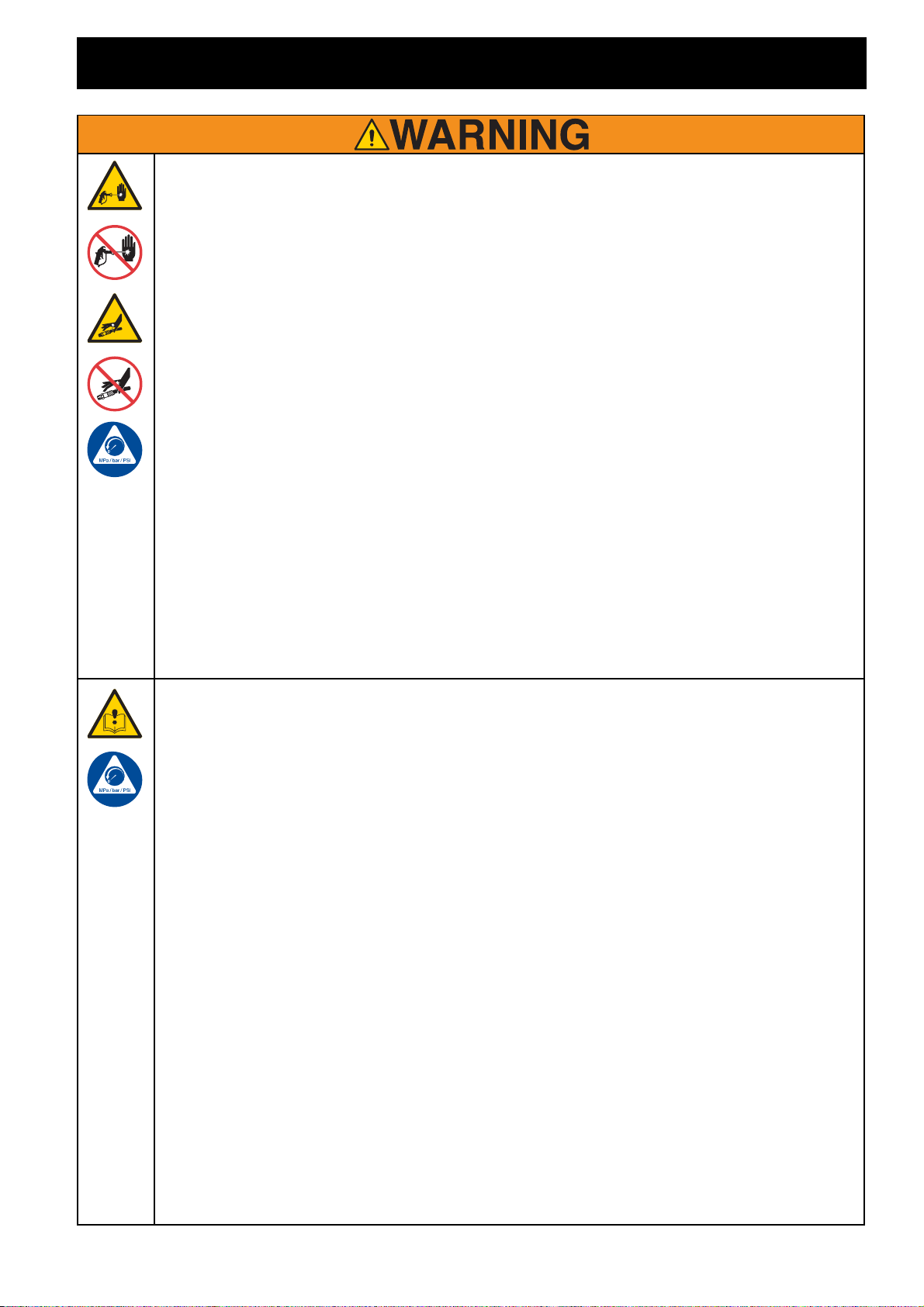
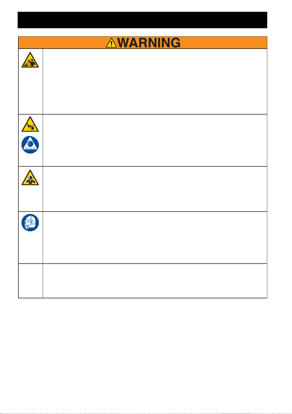
SKIN INJECTION HAZARD
High-pressure spray is able to inject toxins into the body and cause serious bodily
injury. In the event that injection occurs, get immediate surgical treatment.
•Do not aim the gun at, or spray any person or animal.
•Keephandsandotherbody partsawayfromthe discharge.Forexample,donot
try to stop leaks with any part of the body.
•Always use the nozzle tip guard. Do not spray without nozzle tip guard in place.
•Use Graco nozzle tips.
•Use caution when cleaning and changing nozzle tips. In the case where the
nozzletipclogswhilespraying,followthePressure Relief Procedure forturning
off the unit and relieving the pressure before removing the nozzle tip to clean.
•Equipment maintains pressure after power is shut off. Do not leave the
equipment energized orunder pressure while unattended. Followthe Pressure
Relief Procedure when the equipment is unattended or not in use, and before
servicing, cleaning, or removing parts.
•Check hoses and parts for signs of damage. Replace any damaged hoses or
parts.
•This system is capable of producing 3000 psi. Use Graco replacement parts or
accessories that are rated a minimum of 3000 psi.
•Always engage the trigger lock when not spraying. Verify the trigger lock is
functioning properly.
•Verify that all connections are secure before operating the unit.
•Knowhowtostoptheunitandbleedpressurequickly.Bethoroughlyfamiliarwith
the controls.
EQUIPMENT MISUSE HAZARD
Misuse can cause death or serious injury.
•Do not operate the unit when fatigued or under the influence of drugs or alcohol.
•Do not exceed the maximum working pressure or temperature rating of the low-
est rated system component. See Technical Data in all equipment manuals.
•Use fluids and solvents that are compatible with equipment wetted parts. See
Technical Data inallequipmentmanuals.Readfluidandsolventmanufacturer’s
warnings. For complete information about your material, request Safety Data
Sheet (SDS) from distributor or retailer.
•Do not leave the work area while equipment is energized or under pressure.
•Turn off all equipment and follow the Pressure Relief Procedure when equip-
ment is not in use.
•Check equipment daily. Repair or replace worn or damaged parts immediately
with genuine manufacturer’s replacement parts only.
•Do not alter or modify equipment. Alterations or modifications may void agency
approvals and create safety hazards.
•Make sure all equipment is rated and approved for the environment in which you
are using it.
•Use equipment only for its intended purpose. Call your distributor for information.
•Route hoses and cables away from traffic areas, sharp edges,moving parts, and
hot surfaces.
•Do not kink or over bend hoses or use hoses to pull equipment.
•Keep children and animals away from work area.
•Comply with all applicable safety regulations.

Warnings
6 3A2702A
PRESSURIZED ALUMINUM PARTS HAZARD
Use of fluids that are incompatible with aluminum in pressurized equipment can
cause serious chemical reaction and equipment rupture. Failure to follow this
warning can result in death, serious injury, or property damage.
•Do not use 1,1,1-trichloroethane, methylene chloride, other halogenated
hydrocarbon solvents or fluids containing such solvents.
•Do not use chlorine bleach.
•Many other fluidsmay contain chemicals that can react with aluminum. Contact
your material supplier for compatibility.
MOVING PARTS HAZARD
Moving parts can pinch, cut, or amputate fingers and other body parts.
•Keep clear of moving parts.
•Do not operate equipment with protective guards or covers removed.
•Pressurized equipment can start without warning. Before checking, moving, or
servicing equipment, follow the Pressure Relief Procedure and disconnect all
power sources.
TOXIC FLUID OR FUMES HAZARD
Toxic fluids or fumes can cause serious injury or death if splashed in the eyes or on
skin, inhaled, or swallowed.
•Read SDS to know the specific hazards of the fluids you are using.
•Store hazardous fluid in approved containers, and dispose of it according to
applicable guidelines.
PERSONAL PROTECTIVE EQUIPMENT
Wear appropriate protective equipment when in the work area to help prevent
seriousinjury,includingeyeinjury,hearingloss,inhalationoftoxicfumes,andburns.
This protective equipment includes but is not limited to:
•Protective eye wear, and hearing protection.
•Respirators, protective clothing, and gloves as recommended by the fluid and
solvent manufacturer.
CALIFORNIA PROPOSITION 65
•The engine exhaust from this product contains a chemical known to the state of
California to cause cancer, birth defects or other reproductive harm.
This product contains a chemical known to the State of California to cause
cancer, birth defects or other reproductive harm. Wash hands after handling.

Uni-Tip Selection
3A2702A 7
Uni-Tip Selection
69215ST* 2 (5)
69217ST 4 (10)
69315ST 6 (15)
69317ST 6 (15)
69319ST 6 (15)
69321ST 6 (15)
69327ST 6 (15)
69417ST 6-8
(15-20)
69517ST 10 (25)
69615ST* 12 (30)
69617ST 12 (30)
* Use 100 mesh filter to reduce tip
clogs
·²ò
ø½³÷
·²ò
ø½³÷ ·²ò
ø½³÷
·²ò
ø½³÷

Component Identification
8 3A2702A
Component Identification
A Spray Gun Control
B Engine Throttle
C Brake
D Pressure Gauge
E Prime Valve
F Prime Valve
G Gun Trigger Lock
H Engine Controls
J Engine ON/OFF Switch
K Serial Identification Tag
M Pressure Control
N Turn Control

Operation
3A2702A 9
Operation
Setup
1. Ground striper with grounding clamp
during Setup and Cleanup.
2. Eachtimeyoursprayandstore,add3to
5 drops of Throat Seal Oil (TSO) to
decrease packing wear.
3. Checkengineoillevel.AddSAE10W-30
(summer)or5W-20(winter).Seeengine
manual.
4. Fill fuel tank.
5. If removed, install strainer.
6. Openprimevalve.Turnpressurecontrol
counterclockwise to lowest pressure.
NOTE: Minimum hose size allowable for
proper striper operation is 1/4 in. x 50 ft.
The equipment must be grounded to reduce
the risk of static sparking. Static sparking
can cause fumes to ignite or explode.
Grounding provides an escape wire for the
electric current.
¬·ííðê¿
¬·ííðé¿
¬·ííðè
¿
¬·ííðç¿
ti5271a
ti15266a ti15272a

Operation
10 3A2702A
7. Placesiphontubesetingroundedmetal
pail partially filled with flushing fluid.
Attach ground wire to pail and to true
earth ground. Do 1. - 5. of Startup to
flush out storage oil shipped in striper.
Use water to flush water-base paint and
mineralspiritstoflushoil-basepaintand
storage oil.
Pressure Relief Procedure
Follow the
Pressure Relief
Procedure
whenever you see this
symbol.
1. Ground striper with grounding clamp.
2. Turn engine OFF.
3. Turn pressure to lowest setting. Trigger
gun to relieve pressure.
4. Engage gun trigger lock. Open prime
valve.
If you suspect that the Uni-Tip or hose is
completely clogged, or that pressure has not
been fully relieved after following the steps
above, VERY SLOWLY loosen Uni-Tip
Guard retaining nut or hose end coupling to
relieve pressure gradually, then loosen
completely. Then clear tip or hose.
This equipment stays pressurized until
pressure is manually relieved. To help
prevent serious injury from pressurized
fluid, such as skin injection, splashed fluid
and moving parts, follow the Pressure
Relief Procedure whenever sprayer is
stopped and before sprayer is cleaned or
checked, and before equipment is
serviced.
PAINT
FLUSH
¬·ííïð¿
¬·ííðê¿
¬·ëìðë¿
ÑÚÚ
ÑÒ
ti15268ati15272a
ti10352a ti15266a

Operation
3A2702A 11
Startup
1. PerformPressureReliefProcedure.See
Pressure Relief Procedure, page 10.
2. Start Engine.
a. Move fuel valve to open.
b. Move choke to closed.
c. Set throttle to fast.
d. Set engine switch ON.
e. Pull starter cord.
f. After engine starts, move choke to
open.
g. Set throttle to desired setting.
¬·ííïî¿
¬·ííïí¿
ti15279a
ÑÚÚ
ÑÒ
¬·ííïë¿
¬·ííïê¿
¬·ííïé¿
ti3317a
ti15280a

Operation
12 3A2702A
3. Increasepressureenoughtostartpump.
Allow fluid to circulate for 15 seconds.
4. Turn pressure down, close prime valve.
Disengage gun trigger lock.
5. Hold gun against grounded metal
flushing pail. Trigger gun and increase
fluid pressure slowly until pump runs
smoothly.
Inspect fittings for leaks. Do not stop leaks
with your hand or a rag! If leaks occur, turn
striper OFF immediately. Perform Pressure
Relief (page 10). Tighten leaky fittings.
Repeat Startup, steps 1-2. If no leaks,
continue to trigger gun until system is
thoroughly flushed.
Proceed to step 3.
6. Place siphon tube in paint pail.
7. Trigger gun again into flushing fluid pail
until paint appears. Assemble Uni-Tip
and Uni-Tip Guard.
ïë ÍÛÝò
ti15273a
tti10353ati15265a
FLUSH ti15267a ti15273a
PAINT
¬·ííïê¿
FLUSH
ti15267a

Operation
3A2702A 13
Gun Operation
Gun Trigger Lock
Setup
Connect Gun to Striper
1. Attach supply hose to striper fluid outlet.
2. Attach other end of supply hose to gun
swivel. Use two wrenches (one on the
swivelandoneonthehose)totightenall
connections securely.
Uni-Tip and Uni-Tip Guard Assembly
1. Engage trigger lock. Use end of Uni-Tip
(A)to pressUni-TipSeal(B)into Uni-Tip
Guard (D), with curve matching tip bore
(C).
2. Insert Uni-Tip in tip bore and firmly
thread assembly onto gun.
Always engage the trigger lock when the
sprayer is stopped to prevent the gun from
being triggered accidentally by hand or if
dropped or bumped.
Make sure striper is turned off.
Locked
Unlocked
ti10352a ti10353a
A
BC
D
ti10352a
ti15269a
ti15270a
ti15275a

Operation
14 3A2702A
Gun Placement
1. Install Gun: Insert gun into gun holder
with head guard pressed against the
holder assembly bracket.
2. Tighten gun into clamp.
3. Position Gun: Up/down,
forward/reverse, left/right.
NOTE: Verify that the gun can still be
triggered and that the trigger lock can still be
engagedafterinstallation.Makeadjustments
if necessary.
Clearing Tip Clogs
1. Releasetrigger,engageguntriggerlock.
Rotate Uni-Tip. Disengage gun trigger
lock and trigger gun to clear the clog.
2. Engage gun trigger lock, return Uni-Tip
to original position, disengage gun
trigger lock and continue spraying.
ti15292a
ti15393a
ti15276a
ti15277a

Operation
3A2702A 15
Spraying Gun
1. Disengage trigger lock.
2. Be sure the arrow-shaped tip faces
forward (spray).
3. Hold gun perpendicular and
approximately 12 in. (304 mm) from
surface. Move gun first, then pull trigger
to spray a test pattern.
4. Slowly increase pump pressure until
coverage is uniform and even (see
striper instruction manual for additional
information).
Aligning Spray
1. PerformPressureReliefProcedure.See
Pressure Relief Procedure, page 10.
Engage trigger lock.
2. Loosen guard and retaining nut.
3. Align guard horizontally to spray a
horizontal pattern, vertically to spray a
vertical pattern.
Cleanup
Flush gun after each work shift and store in a
drylocation.Donotleavethegunoranyparts
in water or cleaning solvents.
Horizontal Vertical
ti10350a
ti10351a

Operation
16 3A2702A
Clean-up
Perform Pressure Relief Procedure.
See Pressure Relief Procedure, page 10.
1. Remove Uni-Tip Guard and Uni-Tip.
2. Clean gun filter, Uni-Tip Guard and
Uni-Tip in flushing fluid.
3. Remove siphon tube set from paint and
placeinflushingfluid.Usewaterorpump
conditioner for water-base paint and
mineral spirits for oil-base paint.
4. Turn engine ON and start engine.
5. Close prime valve.
6. Hold gun against paint pail. Disengage
guntriggerlock.Graduallyturnpressure
control up until motor begins to drive
pump. Trigger gun until flushing fluid
appears.
7. Move gun to flushing pail, hold gun
against pail, trigger gun to thoroughly
flush system. Release trigger and
engage trigger lock.
ti15274a
FLUSH
Ì×ííéëß
PAINT
FLUSH
¬·ííïð¿
ÑÚÚ
ÑÒ
¬·ííïë¿
ti15265a
ti15268a
ti15267a

Operation
3A2702A 17
8. Openprimevalveandallowflushingfluid
to circulate for 1 to 2 minutes to clean
drain tube.
9. Raise siphon tube above flushing fluid
and run striper for 15 to 30 seconds to
drain fluid.
10. Turn engine OFF.
11. Wipe striper, hose and gun with a rag
soaked in water or mineral spirits.
12. CleanUni-Tip,Uni-TipGuardandgasket
with a soft bristle brush to prevent part
failure due to dried materials. Assemble
parts and attach loosely onto gun.
Handle Bar Adjustment
To adjust height and angle of handle bars,
loosen two nuts (147) and move handle bars
to desired position. Then tighten two nuts
(147).
NOTE: Handle bars can be moved to down
position for storage.
NOTICE
If flushing with water, flush again with pump
conditioner to leave a protective coating to
prevent freezing or corrosion.
ï óî Ó×Òò
ti15266a
ïëóíð ÍÛÝò
PAINT
FLUSH
Ì×ííèíß
¬·ëìðë¿
ÑÚÚ
ÑÒ
Ì×ííèèß
FLUSH
Ì×ííçðß
ti22122a
¬·îîïîî¾

Maintenance
18 3A2702A
Maintenance
Striper
NOTE: Minimum hose size allowable for
proper striper operation is 1/4 in. x 50 ft.
For detailed engine maintenance and
specifications, refer to separate engine
manual supplied.
DAILY: Check engine oil level and fill as
necessary.
DAILY: Check hose for wear and damage.
DAILY: Check gun trigger lock for proper
operation.
DAILY: Check pressure drain valve for
proper operation.
DAILY: Check and fill gas tank.
AFTER THE FIRST 20 HOURS OF
OPERATION: Drain engine oil and refill with
clean oil. See engine manual for correct oil
viscosity.
WEEKLY: Remove air filter cover and clean
element. Replace element if necessary. If
operatinginanunusuallydustyenvironment,
check air filter daily and replace if necessary.
Replacement elements can be purchased
from your local engine dealer.
WEEKLY: Check level of TSO in fluid pump
packing nut. Add 3 to 5 drops if necessary.
Keep TSO in nutto help prevent fluid buildup
on piston rod and premature wear of
packings.
AFTER EACH 100 HOURS OF
OPERATION: Change engine oil. See
engine manual for correct oil viscosity.
SPARK PLUG: Use only BPR6ES (NGK) or
W20EPR-U (NIPPONDENSO) plug. Gap
plugto0.028to0.031in.(0.7to0.8mm).Use
spark plug wrench when installing and
removing plug.
Swivel Wheel
•Stripers are factory aligned, but if
necessary, loosen two bolts (143) on
swivelwheelassemblyjustenoughtobe
able to move the wheel by hand.
•Place turnbuckle over the two mounting
nubs on the frame.
•PressurizetheunitwithwaterandPump
Conditioner and spray out several lines
with the swivel assembly in the locked
position. Use the turnbuckle to fine tune
the alignment of the wheels until the
stripes are straight.
•Tighten bolts (143).
This equipment stays pressurized until
pressure is manually relieved. To help
prevent serious injury from pressurized
fluid, such as skin injection, splashed fluid
and moving parts, follow the Pressure
Relief Procedure whenever sprayer is
stopped and before sprayer is cleaned or
checked, and before equipment is
serviced.

Maintenance
3A2702A 19
Curves and Arcs
•The swivel assembly can be adjusted to
30degreeseithersideofstraightahead.
Place turnbuckle over mounting nubs.
Adjusttothedesiredarcandtightenjam
nuts. If you have arcs that you paint
regularly, purchase additional
turnbuckles (74) and keep them set to
those arc sizes.
Pump
•Alwaysstopthepumpatthebottomofits
stroke when you take a break or at the
end of the day. This helps keep material
from drying on the rod, damaging the
packings.
•Keep the displacement pump packing
nut/wet cup 1/3 full of Throat Seal Oil
(2501) at all times. The TSO helps
protect the packings and rod.
•Lubricate Connecting Rod Pin every
three months.
•Inspect the packing nut daily. The paint
pumphasapatented“TripleLifePacking
System”. Packing life will be extended
significantly if the proper packing
tightening procedure is followed.
PACKING TIGHTENING
PROCEDURE:
Inspect the packing nut daily. If seepage of
paint into the packing nut and/or movement
of the piston upward is found (while not
spraying), the packing nut should be
tightened enough to stop leakage only, but
not any tighter. (Approximately 24 In lbs).
Grease Points
•Fill grease points at swivel wheel until
greasepurgesfromend.Wipeawayany
excess grease. Use only quality-grade
water resistant grease.
Gun
Refer to the 312363 Gun Manual for gun
maintenance procedures.
ti15294a
NOTICE
Do NOT over-tighten packings. Packings
will become damaged and reduce the
packing life.

Troubleshooting
20 3A2702A
Troubleshooting
General Troubleshooting
Problem Cause Solution
Engine Will Not Start Engine switch is OFF Turn engine ON
Engine is out of gas Refill gas tank (see engine
manual).
Engine oil level is low Trytostartengine.Replenish
oil if necessary (see engine
manual).
Spark plug cable is
disconnected or damaged Connect spark plug cable or
replace spark plug.
Cold engine Use choke.
Fuel shut-off lever is OFF Move lever to ON position.
Oil is seeping into
combustion chamber Remove spark plug. Pull
starter 3 to 4 times. Clean or
replace spark plug. Start
engine. Keep striper upright
to avoid oil seepage.
This manual suits for next models
7
Table of contents
Other AIRLESSCO Construction Equipment manuals