BERI UDYOG FIELDKING User manual
1
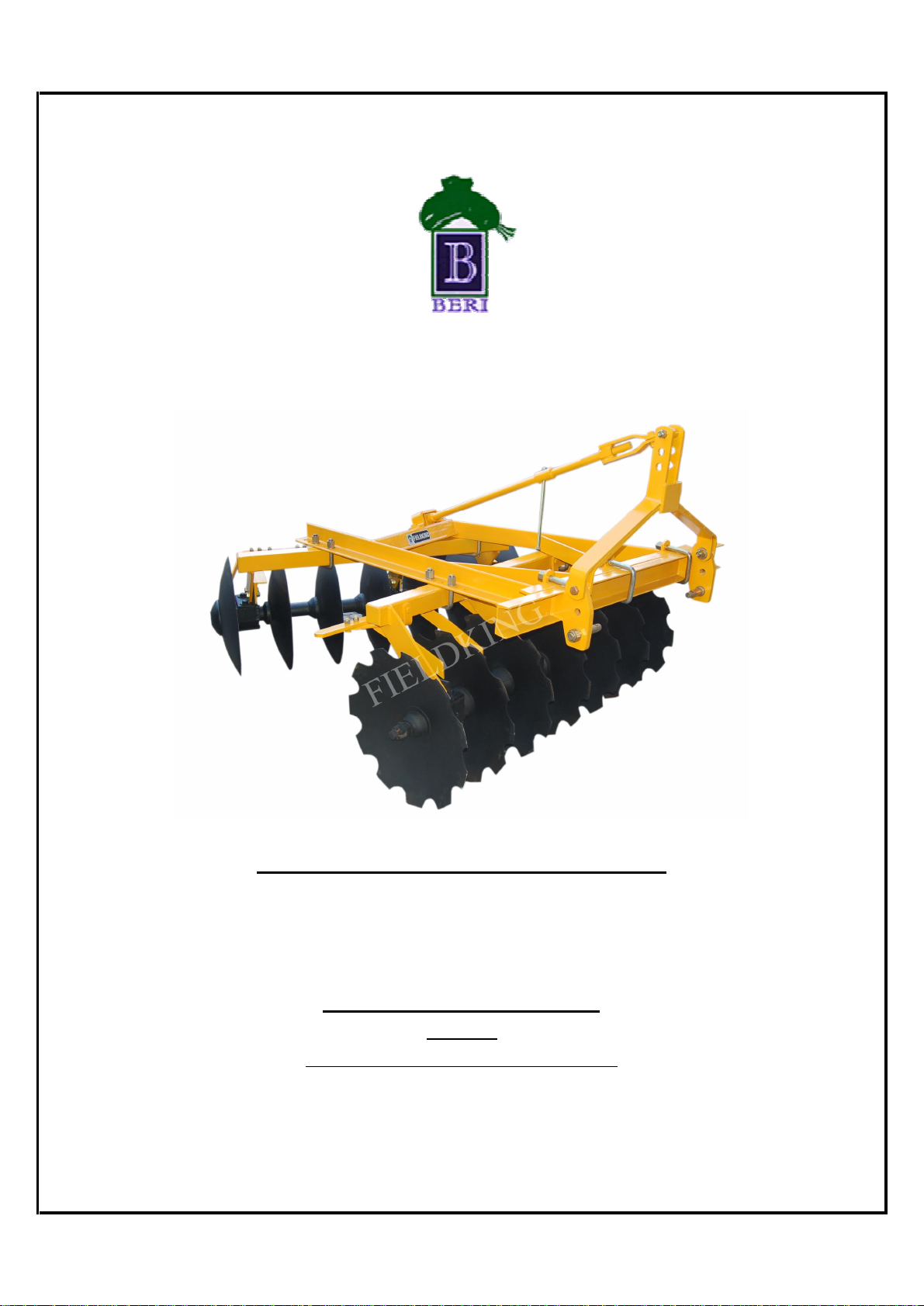
FIELDKING
MOUNTED OFFSET DISC HARROW
BERI UDYOG PVT. LTD.
INDIA
(An ISO 9001-2008 Company)
OPERATOR MANUAL/ SERVICE MANUAL / PART CATALOGUE


3
TO THE PURCHASER
This manual contains valuable information about your new “FIELDKING”
Mounted offset disc harrow. It has been carefully prepared to give you
helpful suggestions for operating, adjusting, servicing and ordering spare
parts.
Keep this manual in a convenient place for quick and easy
reference. Study it carefully. You have purchased a dependable and sturdy
Mounted offset disc harrow, but only by proper care and operation can you
expect to receive the service and long life designed and built into it.
Sometime in the future your Mounted offset disc harrow may
need new parts to replace those that are worn or broken. If so, go to your
dealer and provide him with the model and part number.
Customer Information
Name _______________________________________
Purchased From ______________________________
Date Purchased ______________________________
Model No. ___________________________________
Serial No. ___________________________________

4
It is the purchaser and/or operator’s responsibility to….
1. Read and understand the information contained in this manual.
2. Operate, lubricate, assemble and maintain the equipment in accordance with all
instructions and safety procedures in this manual.
3. Inspect the equipment and replace or repair any parts that are damaged or worn
which under continued operation would cause damage, wear to other parts, or
cause a safety hazard.
4. Return the equipment or parts to the authorized FIELDKING dealer, from where it
was purchased, for service or replacement of defective parts that are covered by
warranty. (The FIELDKING Factory may inspect equipment or parts before
warranty claims are honored.)
5. Payment of all costs incurred by the dealer for traveling to or transporting the
equipment for warranty inspection and claims.

5
INDEX
1.
TECHNICAL DATA
1.1 Introduction
1.2 Warranty
1.3 When the warranty becomes void
1.4 Warning
2.
USAGE INSTRUCTIONS
2.1 Before Use & Adjustments
2.2 Attaching Harrow to the tractor
2.3 Warning for driver
2.4 Safety
3.
MAINTENANCE
3.1 Maintenance Instructions
3.2 Storage of machine after work
3.3 Lubrication
3.4 Instruction for driver
4.
OPERATIONAL GUIDELINES FOR HARROW
5.
TROUBLE SHOOTING CHART

6
1.
TECHNICAL DATA
1.1 INTRODUCTION
This handbook contains the use and maintenance instructions with a list of the spare parts
of the Disc Harrow.
This Disc harrow is equipped with heavy-duty channel frame specially designed for
harrowing / land preparation of rough soil (Secondary finer operation).
Regular and satisfactory operation together with economic and long lasting use of the
implement depends on the compliance with instructions given in this handbook.
Compliance with the instructions in this handbook is also important since Manufacturer
declines all and every responsibility for damage to persons or property caused by
negligence and failure to comply with these instructions.
1.2 WARRANTY
When the machine is delivered, check that it has not been subjected to damage during
transport and that the accessories are in a perfect condition and complete.
Any claims following the receipt of damaged goods shall be presented in writing within 8
days from the receipt of the goods.
The purchaser may only make the claims under guarantee when he has complied with the
warranty conditions in the supply contract.
1.3 WHEN THE WARRANTY BECOMES VOID
Besides the cases specified in the supply agreement, the guarantee shall in any case
become void:
When the implement has been used beyond the specified power limit like (Tractor Horse
Power)
When repairs made by the customer without authorization from the manufacturer or
owing to installation of spurious spare parts, the machine is subjected to variations and
the damage can be ascribed to these variations.
When the user has failed to comply with the instructions in this handbook.
If the implement is used in very hard/stony soil no warranty of discs will be given.
No warranty will be given if the service and greasing is not done on time.
1.4 WARNING
Thoroughly read the instruction manual before proceeding with the various operations.
Maintain the harrow as per the instructions of this handbook to be entitled for
warranty.

7
2. USAGE INSTRUCTIONS
2.1 BEFORE USE & ADJUSTMENTS
1. Before mounting of disc harrow make sure that all nuts & bolts are properly
secured.
2. Also determine soil and trash conditions of the field and make the preliminary
adjustments. e.g.
a) Disc gang angle adjustment :-
Gang angle (Angle between two gangs) ranges between 40
0
to50
0
. The
angle can be increased for better penetration in dry soil while it should be
reduced to avoid plugging in wet soil.
b) Disc harrow leveling: - To eliminate uneven penetration and side draft, leveling
is done by means of top link. While tractor pulls to right the rear gang should be
lowered a little. When the tractor pulls to the left the rear gang should be raised.
c) Scrapper adjustment:-
The scrapper can be adjusted by loosening the bolts at the scrappers clamp.
d) Depth control:-
The depth at which the implement is required to work is controlled
hydraulically by raising or lowering the control lever on the tractor.
e) Disc harrow penetration :-
Factors affecting disc harrow penetration are:-
Angle of the gang
Weight of the harrow
Disc diameter
Disc sharpness
(Blunt disc increases the draft considerably, check the disc sharpness)
Angle of hitch
2.2 ATTACHING THE HARROW TO THE TRACTOR
1. Place the harrow duly leveled on the flat piece of land.
2. Reverse the tractor to the harrow ( Do not drag the harrow up the tractor)
3. Attach the left arm of the tractor to the harrow first.
4. Attach the central arm to the harrow. To attach, turn the screws on both sides to
an equal length. If the arm is too short or too long, turn the screw to adjust both
at the same time until aligned with the hole on the central arm.

8
5. Attach the lower right arm, turn the screw until the mounting pin is at the same
level as the hole on the tractor arm. If the gap between the hole and mounting
pin is too close or too distant, turn the control arm in or pull it away to an
appropriate distance. You may have to adjust both height and distance at the
same time. When the hole at tractor arm and mounting pin are even, insert the
pin in the hole and lock it with the lynch pin.
6. After attaching the harrow, lift it and adjust the control arm parallel to the
ground. When you look from both rear or sideways, the discs should all be
touching the ground uniformly.
2.3 WARNING FOR THE DRIVER
Before harrowing check all nuts & bolts of the disc harrow.
Be vigilant about the tree roots and stones. Don’t harrow on stony soil.
Tractor should be in first high or fourth low gear.
Don’t allow anyone to come across the harrow.
Lift the disc harrow on every turn.
Lift the harrow before approaching the road.
1.4 SAFETY
Understanding the Machine Safety Labels
The machine safety labels shown in this section are
placed in important areas on your machine to draw
attention to potential safety hazards
On your machine safety labels, the words DANGER,
WARNING, and CAUTION are used with this safety-
alert symbol. DANGER identifies the most serious
hazards.
The operator’s manual also explains any potential safety
hazards whenever necessary in special safety messages
that are identified with the word, CAUTION, and the
safety alert symbol.
Before harrowing with Disc harrow take care that nobody stands near it.

9
3. MAINTENANCE
3.1 MAINTENANCE INSTRUCTIONS
If you work the Disc harrow on stony land then maintenance also increases.
1. If the soil has entered the grease nipple, then change the nipple.
2. If disc harrow is new after initial working of first two hours, tighten all nuts &
bolts.
3. After every fifty hours grease all greasing points with grease gun and tighten all
nuts & bolts.
4. After fifty hours, open the bracket spool of Disc harrow & cleanse with diesel oil
& pump in new grease.
3.2 STORAGE OF MACHINE AFTER WORK
1. Wash the Disc harrow after work.
2. Replace the worn out nuts & bolts.
3. If disc harrow has to remain unused for long time then clean it & apply a layer of
used oil for rust prevention.
These steps will enhance the life of your Disc harrow.
In order to protect yourself always wear adequate
clothes and shoes during the operations.
Never allow riders on the tractor or implement unless
on additional seat is available.
Be careful whe
n moving around steep graders to avoid
over turn.
Never transport the implement on rough roads during
the night. When operating, avoid to make sharp turns
that may contact with the implement

10
3.3 LUBRICATION
Please take care that high quality grease is used in spools.
3.4 INSTRUCTIONS FOR DRIVER
1. When Disc harrow is ready for use don’t stand between disc harrow & the
Tractor.
2. Properly fit the three point linkage as mentioned above & lock with lynch pin.
3. In case of scrapper touching the discs, loosen the scrapper bolt and readjusts the
scrapper.
4. Never turn the tractor to the right or left when the harrow is engaged in the soil.
5. Never reverse the tractor when the harrow is engaged in the soil.
6. To get good results from the harrow, disc should be replaced when its diameter
is reduced by 5”from its original size.
4. OPERATIONAL GUIDELINES FOR HARROW
1. Lift the harrow on turning for effective independent breaking of soil.
2. Adjust internal /external check chains to obtain implement swing range with in 50
mm (2”) when raised.
3. Always maintain the correct tyre pressure to avoid wheel slippage.
4. Adding of wheel weights/water ballasting or combination of both is recommended
when excessive rear wheel slippage is experienced.
5. Always set hydraulic levers correctly for draft and position control operation.
The following settings are necessary to ensure that uniform working depth is
maintained:-
a.) Side draft:-
The offset disc harrow will trail correctly behind the tractor provided the side thrust of
the front gang is equal to that of rear. In case it is different there will be side draft. To set
it correctly, the gang angle should be changed.
b.) Severe Side Draft:-
In case of severe side draft the cutting depth of rear disc gang should be increased or
decreased with the help of tractor top link. For instance when tractor pulls to right, lower
the rear gang and when tractor pulls to left, raise the rear gang.
Precautions during transportation:-
1. When transporting the harrow, shorten up top link to minimum length.
2. Set hydraulic levers in top raised position and lock levers.
3. Maintain the speed to avoid jumps.
4. Watch while overtaking on road.
5. Always use SMV (Slow Moving Vehicles) symbols.

11
5. TROUBLE SHOOTING CHART
SR.
NO.
POSSIBLE CAUSES
POSSIBLE REMIDIES
A. Side Draft
1.
Disc not running level
Adjust using leveling lever
2.
Gangs improperly angled
Set the gangs
3.
Too much left hand offset.
Swing
the hitch to the left.
B. Excessive field slippage
1.
Tractor overloaded
Reduce angle, reduce depth.
2.
Not enough tractor ballast
Add wheel weight or liquid
C. Not filling the furrow
1.
Too much left hand offset
Swing hitch to the left
2.
Tracto
r wheel running in furrow enlarging
it
Drive the tractor in unworked ground
3.
Disc too far from furrow
Keep the left front discs in furrow
4.
Rear gang set wrong, laterally.
Move the rear gang right or left. The left
rear should be centered in the space
between left front discs.
D. Poor penetration
1.
Hard ground
Swing hitch to the right. Increase angle in
front and rear gang.
E. Disc unsteady
1.
Too much angle in gang
Reduce the gang angle
F. Gang plugging
1.
Field too wet.
Disc at shallo
w depth for first pass to
speed
up drying process.
2.
Gang set in maximum angle.
Reduce the angle
3.
Not using scrappers
Install scrappers.
4.
Scrappers worn out or not set properly.
Replace worn ones. Adjust scrappers
close to the disc
5.
Discing too
deep in damp soil
Reduce penetration

12

13

14

15

16

17

18

19
Other manuals for FIELDKING
1
Table of contents
Popular Farm Equipment manuals by other brands


Z.I.P.P.ER MASCHINEN
Z.I.P.P.ER MASCHINEN ZI-MD500HST user manual

Frontier
Frontier RT 1142 Operator's manual

APV
APV PS 300 M1 D operating instructions

Fast
Fast 8200 Operation manual

Goldacres
Goldacres ATV75 Operator's & parts manual

Farmi Forest Corporation
Farmi Forest Corporation VARIO 101 Operating, Maintenance and Spare Parts Manual


