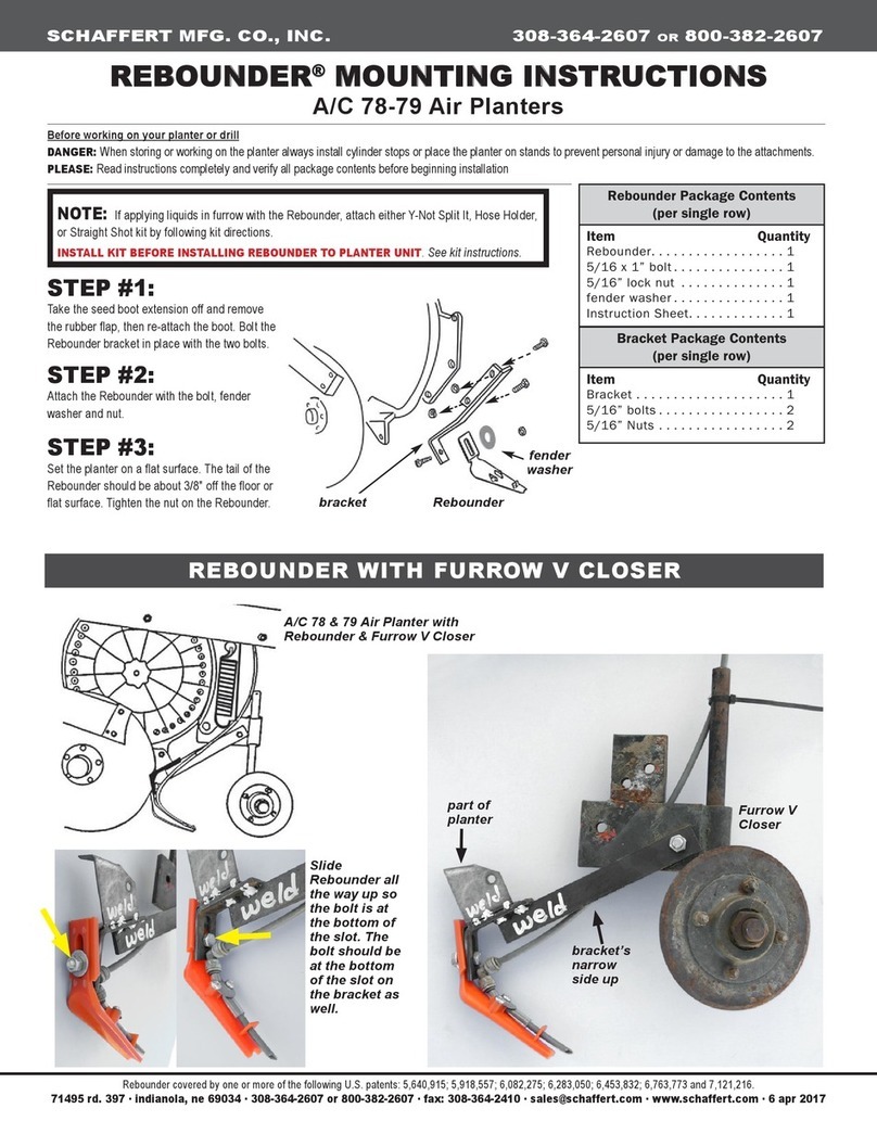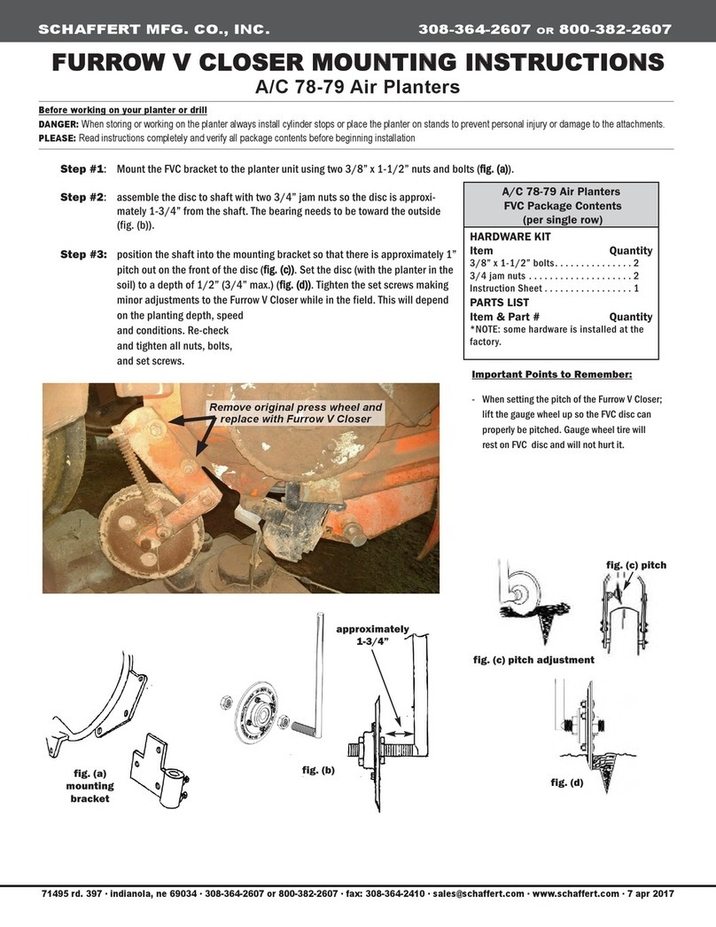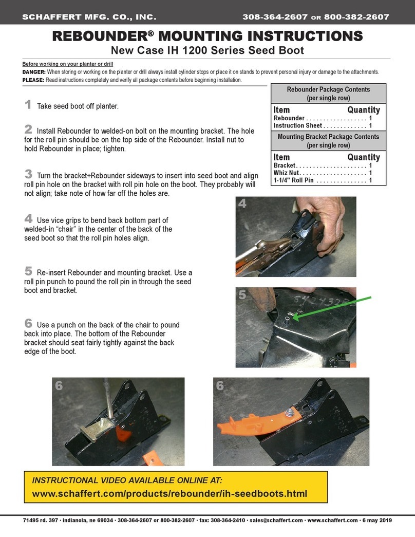
G2™ G3™ G4™ MOUNTING INSTRUCTIONS
SCHAFFERT MFG. CO., INC. 308-364-2607 OR 800-382-2607
71495 rd. 397 ∙ indianola, ne 69034 ∙ 308-364-2607 or 800-382-2607 ∙ fax: 308-364-2410 ∙ sales@schaffert.com ∙ www.schaffert.com ∙ 17 mar 2020
Before working on your planter or drill
DANGER:
When storing or working on the planter always install cylinder stops or place the planter on stands to prevent personal injury or damage to the attachments.
PLEASE:
Read instructions completely and verify all package contents before beginning installation.
‼
NOTE:
There are
left-hand
and
right-hand
G2, G3, and G4 units. Lefts and rights are
determined facing planter from the back.
‼
NOTE: WHEN YOU PICK THE PLANTER UP, THE GAUGE WHEEL
WILL HIT THE PRESS WHEEL.
When you set the planter back down, the gauge wheel
will go forward and the tail section will go backward so that they will not hit while running
in the eld.
WHEN INSTALLING THE G2/G3/G4 EITHER TIE THE GAUGE
WHEEL FORWARD OR THE TAIL SECTION UP.
OVER ▬
►
Installing the Fertilizer Bracket & Disc to the Arm Bracket
[]
Corresponds with PART#:
G2HL, G2HR, G2HLPT, G2HRPT, G3HL,
G3HR, G4HL, G4HR, G4HLPT, G4HRPT
Part 1 of 2 Parts List
Horsch
Fertilizer Disc
Package Contents (per single row)
Item Quantity
Arm............................. 1
Mounting Bracket.................. 1
(continued on part 2)
Horsch Maestro Wheel Bolt
Package Contents (per single row)
Item Quantity
Stainless Steel Axle Bolt . . . . . . . . . . . . 1
with 5/8″ fine thread nut ......... 1
Blue 3/8″ Spacer .................. 2
5/8″ x 1-1/4″ Button Head Bolt........ 4
5/8″ Jam Nut (Half Nut) ............. 4
(continued on part 2)
1. Remove both press wheels from tail section of planter.
2. Bolt the mounting bracket using the four 5/8″ button head bolts and jam nuts to the tail
section, placing blue spacers between the tail section and mounting bracket.
3. Position the different arms in between the mounting bracket, as follows:
G2:
With the single prong of the arm bracket pointing to the front and the double
prongs pointing out the back.
G3:
With the cut-out end of the arm pointing to the front.
G4:
With the thicker end for fastening the disc mounting plate pointing to the back.
Center the hole of the arm with the openings at the base on the mounting bracket,
and slide the stainless axle bolt through both the mounting bracket and arm bracket.
Thread the 5/8″ ne thread nut on the outside of the axle bolt.
4. Use a hammer to seat the knurled end of the bolt in the bracket and tighten bolt and
nut with two 15/16 wrenches.
Part 1 of 2: Installing the Arm Bracket to the Tail Section
Horsch Maestro Planters


