manuals.online logo
Brands
  1. Home
  2. •
  3. Brands
  4. •
  5. Samson
  6. •
  7. Controllers
  8. •
  9. Samson 3277 User manual

Samson 3277 User manual

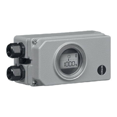
i/p Positioners Types3730‑4/‑5
This Quick Guide does not substitute the mounting and operating
instructions delivered with the positioner. The warnings and safety
instructions in the mounting and operating instructions must be
followed.
1 Mounting
Direct attachment to SAMSON Type3277 Actuator
Travel [mm]Actuator [cm²] Lever Pin position
7.5 120 M25
15 120, 175, 240, 350 M35
30 355, 700, 750 M50
ÎTo mount the positioner, lift the lever so that the follower pin rests
on the follower clamp of the actuator stem. Make sure the lever
can move freely.
NAMUR attachment
Travel [mm] Actuator [cm²] Travel Pin position
7.5 60, 120 with Type3510 Valve S17
7.5 120 M25
7.5 700, 750 M35
15 120, 175, 240, 350 M35
15, 30 355, 700, 750 M50
30 1000, 1400, 2800 L70
60 1000, 1400, 2800 L100
120 1400, 2800 XL 200
200 See manufacturer‘s specations XXL 300
ÎDetermine the travel range of the control valve (closed position to
as far it will go in the other direction) by applying the max. supply
air to the actuator and then venting the actuator completely.
Î
Fasten the lever with the follower pin onto the shaft of the
positioner.
Î
Fasten the NAMUR bracket onto the valve yoke so that it is aligned
centrally to the slot of the follower plate when the travel position
is at approx. 50%.
ÎFasten the positioner to the NAMUR bracket, making sure that the
follower pin is in the slot of the follower plate. Make sure the lever
can move freely.
Attachment to rotary actuators
Lever Pin position
M90°
ÎPlace the valve into the closed position. Determine the opening
direction.
ÎPlace the follower plate on the slotted actuator shaft and fasten it
to the coupling wheel. Mount the top and bottom brackets to the
actuator.
ÎFasten the positioner on the bracket. Make sure that:
–The lever with its follower pin engages the slot of the coupling
wheel, while taking into account the opening direction.
–
The lever in the middle valve position is parallel to the long side
of the positioner housing.
2 Start‑up
1. Apply supply air (1.4 to 7bar).
2. Connect electrical reference variable according to IEC61158-2.
i/p‑Stellungsregler Typ3730‑4/‑5
Die vorliegende Kurzanleitung ersetzt nicht die dem Gerät beiliegen-
de Einbau- und Bedienungsanleitung. Die in der Einbau- und Bedie-
nungsanleitung enthaltenen Sicherheits- und Warnhinweise sind zu
beachten.
1 Montage
Direktanbau an SAMSON-Antrieb Typ3277
Hub [mm]Antrieb [cm²] Hebel Stiftposition
7, 5 120 M25
15 120, 175, 240, 350 M35
30 355, 700, 750 M50
ÎZur Montage des Stellungsreglers den Hebel anheben, damit der
Abtaststift auf dem Mitnehmer der Antriebsstange zum Liegen
kommt. Auf freie Hebelbeweglichkeit achten.
NAMUR‑Anbau
Hub [mm]Antrieb [cm²] Hebel Stiftposition
7, 5 60, 120 mit SAMSON-Ventil Typ 3510 S17
7, 5 120 M25
7, 5 700, 750 M35
15 120, 175, 240, 350 M35
15, 30 355, 700, 750 M50
30 1000, 1400, 2800 L 70
60 1000, 1400, 2800 L100
120 1400, 2800 XL 200
200 vgl. Herstellerangabe XXL 300
Î
Hubbereich des Stellventils (Stellung ZU bis zum gegenüberlie-
genden Anschlag) durch volles Be- und Entlüften ermitteln.
Î
Entsprechenden Hebel mit Abtaststift auf der Welle des Stellungs-
reglers verschrauben.
ÎNAMUR-Winkel so am Ventiljoch festschrauben, dass er bei ca.
50% Hubstellung mittig zum Schlitz der Mitnehmerplatte steht.
Î
Stellungsregler am NAMUR-Winkel befestigen. Der Abtaststift
muss im Schlitz der Mitnehmerplatte liegen. Auf freie Hebelbe-
weglichkeit achten.
Anbau an Schwenkantriebe
Hebel Stiftposition
M90°
ÎVentil in ZU-Stellung bringen. Öffnungsrichtung bestimmen.
ÎMitnehmer auf die geschlitzte Antriebswelle aufstecken und zu-
sammen mit Kupplungsrad verschrauben. Untere und obere Be-
festigungswinkel am Antrieb montieren.
ÎStellungsregler am Winkel festschrauben. Darauf achten, dass
–
der Hebel mit seinem Abtaststift unter Berücksichtigung der
Öffnungsrichtung in den Schlitz des Kupplungsrads eingreift.
–der Hebel in der mittleren Hubstellung parallel zur Längsseite
des Stellungsreglergehäuses steht.
2 Inbetriebnahme
1. Pneumatische Hilfsenergie (1,4 bis 7bar) aufschalten.
2. Elektrischen Sollwert gemäß IEC61158-2 anschließen.
!
българскиезик[BG] · Čeština[CS] · Dansk[DA] · Deutsch[DE] · ελληνικά[EL]
English[EN] · Español[ES] · Eesti[ET] · Suomi[FI] · Français[FR]
Hrvatskijezik[HR] · Magyar[HU] · Italiano[IT] · 日本語 [JA]
Lietuviųkalba[LT] · Nederlands[NL] · Polski[PL] · Português[PT]
Română [RO] · Русский[RU] · Slovenčina[SK] · Slovenščina[SL] ·
Svenska[SV] · Türkçe[TR] · 中文[ZH]
Îwww.samson.de
Edition March 2016 Quick Guide KA 8384‑5 EN
Set the fail‑safe position of the valve at the slide switch:
ÎAIR TO OPEN (signal pressure opens the valve)
ÎAIR TO CLOSE (signal pressure closes the valve)
Adapt the volume restriction Q (only <240cm²):
MIN SIDE for connection at the side
MIN BACK for connection at the back
ÎInitialize the positioner (see overleaf).
3 Conguration and operation
Each parameter has a code number which is shown in the display.
Parameters that have a code marked with * can only be changed
when they are enabled beforehand using Code3(display: ).
–Select parameter/value: turn rotary pushbutton ()
–Conrm parameter/value: press rotary pushbutton ()
–Cancel action: until ESC then 
4 Initialization
Initialization mode: MAX (see EB for other modes)
WARNUNG! Risk of crushing! During the initialization, the control
valve moves through its entire travel range/angle of rotation.
Note: After changing the installation, reset the positioner before
initialization (Code 36/Std).
ÎMount and start up the positioner, then press INIT key. READY!
The positioner adapts itself automatically to the maximum travel/
rotational angle range of the control valve.
After applying the set point, the positioner goes to the last used
operating mode. Code0appears on the display.
5 Codes/icons and their meaning
For detailed information on mounting and operation, refer to:
uEB8384-4 for Type3730-4, uEB8384-5 for Type3730-5
Code Meaning
0Operating mode
1Manual w
2Reading direction
3Enable conguration
4* Pin position
5* Nominal range
6* Initialization mode
7* Direction of action
8*/9 Travel/angle range start/end
10/11* Travel/angle upper/lower limit
12/13* w-start/end
14/15* Set point cutoff decrease/
increase
16* Pressure limit
17/18* Kp/Tv step
19* Tolerance band
Code Meaning
20* Characteristic
21/22* Required transit time OPEN/
CLOSED
23* Total valve travel
24* LV total valve travel
34* Closing direction
35* Blocking position
36* Reset
37* Position transmitter option
38* Inductive alarm
39-45 Information (see EB)
50-56 Initialization errors (see EB)
57-60 Operational errors (see EB)
62-67 Hardware errors (see EB)
68-78 Data errors (see EB)
79-81 Diagnosis errors (see EB)
Legend: w = set point; x = travel
Icon Meaning
Conguration enabled
Maintenance demanded
SFail-safe position
blinks Not initialized
blinks Emergency mode
Icon Meaning
Err Error
TunE Autotuning
ZP Zero calibration
Ausgabe März 2016 Kurzanleitung KA 8384‑5
Sicherheitsstellung des Stellventils am Schiebeschalter einstellen:
ÎAIR TO OPEN, wenn Stelldruck das Ventil öffnet
ÎAIR TO CLOSE, wenn Stelldruck das Ventil schließt
Volumendrossel Q anpassen (nur für Antriebsächen <240cm²):
MIN SIDE bei seitlichem Anschluss
MIN BACK bei rückseitigem Anschluss
ÎStellungsregler initialisieren (vgl. Rückseite).
3 Konguration und Bedienung
Jedem Parameter ist ein Code zugeordnet, derim Display angezeigt
wird. Parameter,die zu einem mit * gekennzeichneten Code gehören,
können nur dann verändert werden, wenn vorher über Code3die
Freigabe erfolgt ist (Anzeige: ).
–Parameter/Wert auswählen: Dreh-/Druckknopf drehen ()
–Parameter/Wert bestätigen: Dreh-/Druckknopf drücken ()
–Bedienhandlung abbrechen: bis ESC dann 
4 Initialisierung
Initialisierungsmodus: MAX (andere vgl. EB)
WARNUNG! Quetschgefahr! Während der Initialisierung durchfährt
das Ventil den gesamten Hub-/Winkelbereich.
Hinweis: Nach Änderung der Einbausituation, den Stellungsregler
vor der Initialisierung resetten (Code 36/Std).
ÎMontieren, Inbetriebnehmen und Taste INIT drücken. FERTIG!
Der Stellungsregler adaptiert sich vollautomatisch auf den maxi-
malen Hub-/Drehwinkelbereich des Stellventils.
Nach Anlegen deselektrischen Sollwerts bendet sich das Gerät in
der zuletzt benutzten Betriebsart. Im Display wird Code0angezeigt.
5 Codes/Symbole und ihre Bedeutung
Einzelheiten vgl. zugehörige Einbau- und Bedienungsanleitungen:
uEB8384-4 für Typ3730-4, uEB8384-5 für Typ3730-5
Code Bedeutung
0Betriebsart
1Hand-w
2Leserichtung
3Kongurationsfreigabe
4* Stiftposition
5* Nennbereich
6* Initialisierungsmode
7* Bewegungsrichtung
8*/9 x-Bereich Anfang/Ende
10/11* x-Grenze unten/oben
12/13* x-Anfang/-ende
14/15* w-Endlage größer/kleiner
16* Druckgrenze
17/18* Kp/Tv-Stufe
19* Toleranzband
Code Bedeutung
20* Kennlinie
21/22* w-Rampe Auf/Zu
23* Wegintegral
24* Grenzwert Wegintegral
34* Schließrichtung
35* Blockierstellung
36* Reset
37* Stellungsmelderoptionen
38* Induktiv-Alarm
39...45 Informationen (vgl. EB)
50...56 Feher Initialisierung (vgl. EB)
57...60 Fehler Betrieb (vgl. EB)
62...67 Fehler Hardware (vgl. EB)
68...78 Fehler Daten (vgl. EB)
79...81 Fehler Diagnose (vgl. EB)
Legende: w = Sollwert; x = Hub
Symbol Bedeutung
Kongurationsfreigabe
Wartungsanforderung
SSicherheitsstellung
blinkt nicht initialisiert
blinkt Notmodus
Symbol Bedeutung
Err Fehler
TunE Selbstabgleich
ZP Nullpunktabgleich
Other manuals for 3277

3

Other Samson Controllers manuals

Samson 3274 Service manual

Samson

Samson 3274 Service manual

Samson 46-7 Service manual

Samson

Samson 46-7 Service manual

Samson SS AT054U Service manual

Samson

Samson SS AT054U Service manual

Samson TROVIS 5757-7 Service manual

Samson

Samson TROVIS 5757-7 Service manual

Samson TROVIS 5724-8 Service manual

Samson

Samson TROVIS 5724-8 Service manual

Samson 46-5 Service manual

Samson

Samson 46-5 Service manual

Samson 3271-5 Service manual

Samson

Samson 3271-5 Service manual

Samson 43-6 Service manual

Samson

Samson 43-6 Service manual

Samson Type 4708 Service manual

Samson

Samson Type 4708 Service manual

Samson 3222/5724 Service manual

Samson

Samson 3222/5724 Service manual

Samson TROVIS 5757-3 Service manual

Samson

Samson TROVIS 5757-3 Service manual

Samson 5821 User manual

Samson

Samson 5821 User manual

Samson TROVIS 5573 Service manual

Samson

Samson TROVIS 5573 Service manual

Samson 3372 Service manual

Samson

Samson 3372 Service manual

Samson 3374 User manual

Samson

Samson 3374 User manual

Samson TROVIS 5572 Service manual

Samson

Samson TROVIS 5572 Service manual

Samson 3277-5 Service manual

Samson

Samson 3277-5 Service manual

Samson TROVIS 5432 Service manual

Samson

Samson TROVIS 5432 Service manual

Samson 2479 Service manual

Samson

Samson 2479 Service manual

Samson TROVIS 5579 Service manual

Samson

Samson TROVIS 5579 Service manual

Samson SAM -01 Service manual

Samson

Samson SAM -01 Service manual

Samson TROVIS 5757-7 Service manual

Samson

Samson TROVIS 5757-7 Service manual

Samson TROVIS 5433 User manual

Samson

Samson TROVIS 5433 User manual

Samson 3271 Service manual

Samson

Samson 3271 Service manual

Popular Controllers manuals by other brands

MSR ELECTRONIC PolyGard SPC3-11 Series user manual

MSR ELECTRONIC

MSR ELECTRONIC PolyGard SPC3-11 Series user manual

Woodward DTSC-200A Installation

Woodward

Woodward DTSC-200A Installation

Cisco WS-C5008B - Power Supply - 1100 Watt installation guide

Cisco

Cisco WS-C5008B - Power Supply - 1100 Watt installation guide

Azbil BC-R35 Series specification

Azbil

Azbil BC-R35 Series specification

AVM B1 PCI v4.0 manual

AVM

AVM B1 PCI v4.0 manual

rotork IQT Series Installation and maintenance instructions

rotork

rotork IQT Series Installation and maintenance instructions

HighPoint Rocket 700L Series manual

HighPoint

HighPoint Rocket 700L Series manual

SpectraPure UltraPrecise ATO installation manual

SpectraPure

SpectraPure UltraPrecise ATO installation manual

Biamp IMPERA ECHO PLUS installation manual

Biamp

Biamp IMPERA ECHO PLUS installation manual

Tannoy TDX2 user manual

Tannoy

Tannoy TDX2 user manual

Akyga AK-CA-73 user manual

Akyga

Akyga AK-CA-73 user manual

Instrutech VGC301 user manual

Instrutech

Instrutech VGC301 user manual

Rath 2500-LUPSM installation guide

Rath

Rath 2500-LUPSM installation guide

Johnson MISTRALSUC75 manual

Johnson

Johnson MISTRALSUC75 manual

Eurtotherm 2216e Engineering handbook

Eurtotherm

Eurtotherm 2216e Engineering handbook

Wheelock SP-SVC installation instructions

Wheelock

Wheelock SP-SVC installation instructions

Carel Carel c.pCOMini quick guide

Carel

Carel Carel c.pCOMini quick guide

Rosslare AYC-B7661 installation manual

Rosslare

Rosslare AYC-B7661 installation manual

manuals.online logo
manuals.online logoBrands
  • About & Mission
  • Contact us
  • Privacy Policy
  • Terms and Conditions

Copyright 2025 Manuals.Online. All Rights Reserved.