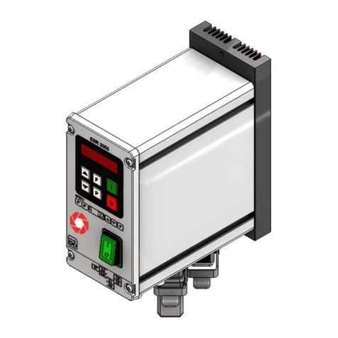
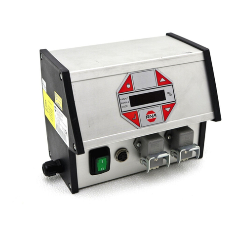
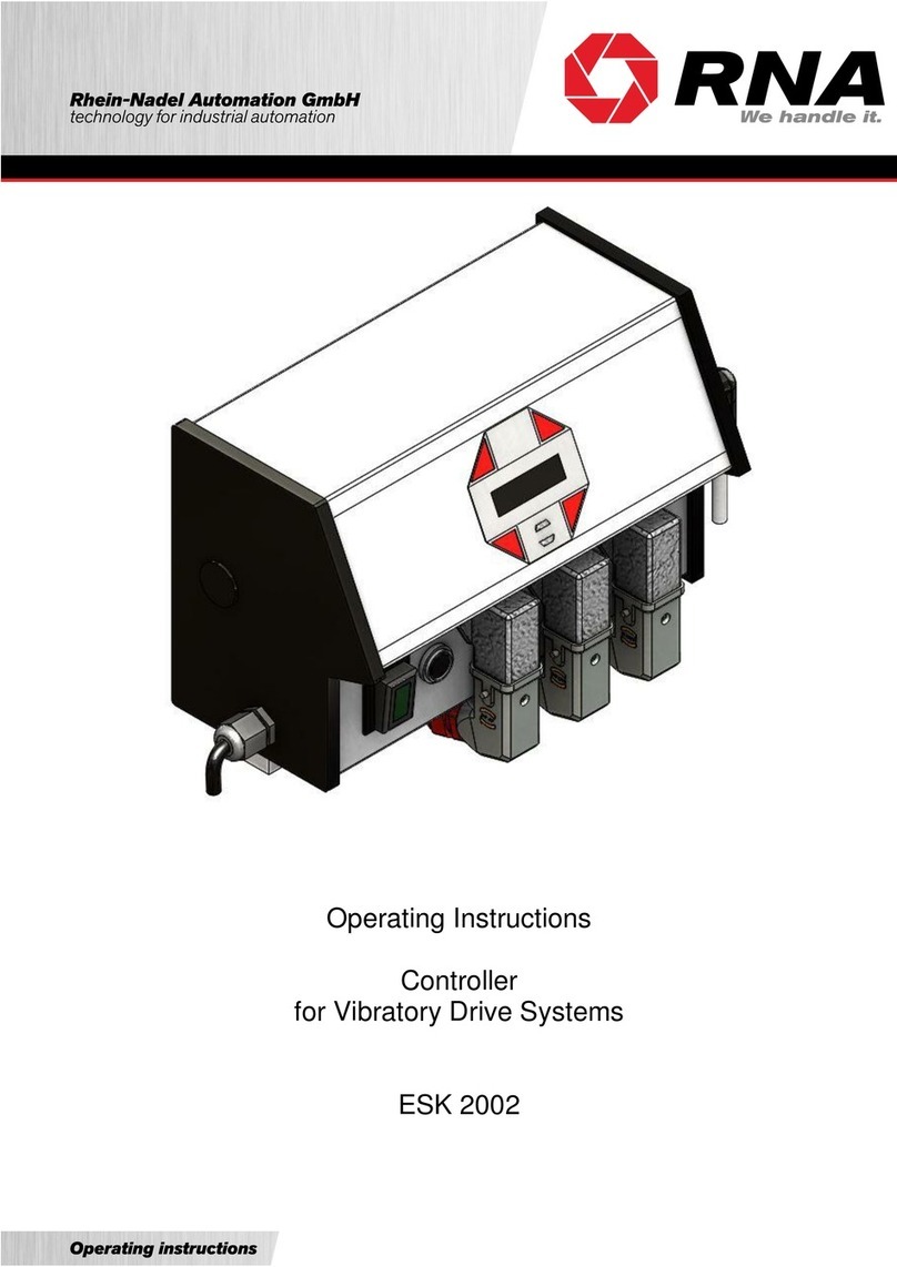
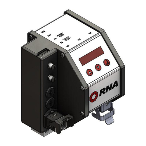
RNA ESR 2500 User manual

Operating Instructions
Controller for vibrating motors
ESR 2500
ESR 2800

Rhein-Nadel Automation GmbH 2
VT-BA-ESR2500-2800_EN-2020 / 09.04.2019 SJ
Table of Contents
1. About this document............................................................................................................4
2. Safety directives..................................................................................................................4
2.1. Design of safety directives ..................................................................................................4
2.2. Fundamental safety directives.............................................................................................4
2.3. Personnel............................................................................................................................4
2.4. Intended use........................................................................................................................5
2.5. Residual hazards.................................................................................................................5
2.5.1. Device.................................................................................................................................5
2.5.2. Motor protection ..................................................................................................................5
2.5.3. Degree of protection - Protection of persons and equipment ..............................................6
3. Product information.............................................................................................................6
3.1. Functional description .........................................................................................................6
3.2. Standard features................................................................................................................6
3.3. Applied standards................................................................................................................7
4. Installation and commissioning............................................................................................7
4.1. Sequence of operations for installation and commissioning................................................7
4.2. Mechanical installation........................................................................................................8
4.3. Electrical installation............................................................................................................8
4.4. Commissioning....................................................................................................................9
4.5. Choice of the right current range.........................................................................................9
4.6. Sensor connection.............................................................................................................12
4.7. Connection diagram..........................................................................................................13
4.8. Voltage change .................................................................................................................14
5. Operator panel and display of the controller......................................................................15
5.1. Operator panel - Display ...................................................................................................15
5.2. Navigating through the menus...........................................................................................16
5.3. Main menu ........................................................................................................................16
5.3.1. The "Status" screen:..........................................................................................................16
5.3.2. The "Info" screen:..............................................................................................................17
5.3.3. The "Extended" screen:.....................................................................................................17
5.3.4. Summary of ESR 2500, ESR2800 main menu..................................................................18
6. The set-up menu...............................................................................................................18
6.1. List of set-up menu items ..................................................................................................18
6.1.1. Accumulation checker (sensor inputs)...............................................................................19
6.1.2. Ramps...............................................................................................................................19
6.1.3. Display calibration.............................................................................................................20
6.1.4. Communication / connector XS3.......................................................................................20
6.1.5. Analogue speed input........................................................................................................21
6.1.6. High / Low speed...............................................................................................................21
6.1.7. Multiple settings.................................................................................................................21
6.1.8. Active braking....................................................................................................................22
6.1.9. Changing the password.....................................................................................................22
6.1.10. Activation code..................................................................................................................22
7. Calibration menu...............................................................................................................22
7.1. List of calibration menu items............................................................................................22
7.1.1. Start calibration .................................................................................................................22
7.1.2. Fine tuning ........................................................................................................................23
7.1.3. Current sensor configuration.............................................................................................23
7.1.4. Set max. current................................................................................................................23
7.1.5. Mode.................................................................................................................................23
7.1.6. Changing the password.....................................................................................................23
7.2. Calibration process............................................................................................................24
8. Memory Reset...................................................................................................................28

Rhein-Nadel Automation GmbH 3
VT-BA-ESR2500-2800_EN-2020 / 09.04.2019 SJ
9. Technical data...................................................................................................................28
9.1. Accessories.......................................................................................................................29
10. Alarm messages................................................................................................................29
10.1. Alarm message and troubleshooting.................................................................................29
10.1.1. Short-circuit protection active............................................................................................29
10.1.2. Overload protection active.................................................................................................30
10.1.3. No feeder or low current....................................................................................................30
10.1.4. Frequency error.................................................................................................................30
10.1.5. Vibration restricted ............................................................................................................31
10.1.6. Resonance frequency not found........................................................................................31
10.1.7. Resonance maximum not found........................................................................................31
10.1.8. PWM measurement offset error ........................................................................................31
10.1.9. Voltage measurement offset error.....................................................................................31
10.1.10. Current measurement offset error .................................................................................31
10.1.11. Offset error refusing common mode, distance measurement........................................32
10.1.12. Magnet core saturation not found..................................................................................32
10.1.13. Field bus error ...............................................................................................................32
11. General errors...................................................................................................................32
Declaration of Conformity
According to the Low-Voltage Directive 2014/35/EU
and Electromagnetic Compatibility Directive 2014/30/EU
We hereby declare that the product meets the following requirements:
Low-Voltage Directive 2014/35/EC
Electromagnetic Compatibility Directive 2014/30/EU
Applied harmonised standards: DIN EN 60204 T1
EN 61439-1
Remarks:
Rhein-Nadel-Automation
---------------------------------
Managing Director
Jack Grevenstein

Rhein-Nadel Automation GmbH 4
VT-BA-ESR2500-2800_EN-2020 / 09.04.2019 SJ
1. About this document
The information given in this document reflects the following version:
Document description:
This document provides assistance in choosing your product. You will also find information on mechanical and electri-
cal installation, operation, product extensions and accessories.
Non-observance may cause trouble with the product or the environment, reduce the product lifetime or lead to other
damage.
2. Safety directives
2.1. Design of safety directives
2.2. Fundamental safety directives
Non-observance of the following fundamental safety measures and directives may lead to severe injury and damage to
property!
Meeting the requirements given in the related documentation is a precondition for safe and trouble-free operation and
for achieving the product properties specified. Further additional safety directives in the other sections must be observed
as well.
2.3. Personnel
Only qualified professionals are allowed to work on or with the product. IEC 60364 or
CENELEC HD 384 define the qualification of these persons:
•They are familiar with set-up, installation, commissioning and operation of the product.
•They possess the qualification required for performance of their work.
•They know all regulations for the prevention of accidents, directives and laws applicable to set-up, installation and
commissioning on site, and they are able to apply the same.
•They have knowledge and skills of First Aid.
Attention
Read this document carefully and observe the safety directives before commencing any work.
Product
from software version
Date
ESR2500
V1.2.7
2019-03-01
ESR2800
V1.2.7
2019-03-01
Notice
This notice identifies useful tips for use of the controller.
Attention!
This symbol identifies hazardous situations.
Non-observance of such warnings may cause irreversible injury or even death!
Attention!
Any work on electrical equipment of the machine/system shall be carried out exclusively by a professional
electrician, or by instructed persons working under the direction and supervision of a professional electri-
cian, according to electrotechnical rules.

Rhein-Nadel Automation GmbH 5
VT-BA-ESR2500-2800_EN-2020 / 09.04.2019 SJ
2.4. Intended use
Please observe the following directives for intended use of the controllers:
•The devices herein described must only be stored, fitted and operated under the conditions specified in this doc-
umentation.
•Here you are not concerned with domestic devices! They are solely intended to be used as components for
commercial or professional applications pursuant to EN 61000−3−2.
•They satisfy the protection requirements of 2014/35/EU: Low Voltage Directive.
•They do not constitute a machine as defined by 2006/42/EU: Machinery Directive.
•A machine comprising the product must not be commissioned or put into operation for the intended use until it
has been declared to be in conformity with the EC Directive 2006/42/EU: Machinery Directive; Observe EN
60204−1.
•Commissioning or starting operation for the intended use is only permitted in compliance with the EMC Directive
2014/30/EU.
•Use of the product in living areas may lead to EMC disturbance. The user is responsible for taking interference
suppression measures.
•They are optimised for operation of RNA bowl feeders and linear feeders. Observe the limits indicated in the
technical specification.
2.5. Residual hazards
Residual hazards may remain even if all directives have been observed and protective measures taken.
Such residual hazards must be considered by the user in the risk assessment of his machine/equipment. Non-ob-
servance may lead to severe injury and damage to property!
2.5.1. Device
Pay attention to the warning signs fitted to the device!
Symbol
Description
Hazardous voltage:
Prior to commencing any work on the product check for absence of voltage on all power con-
nections.
Leakage current:
Make fixed installation and PE connection according to EN 60204−1!
Attention
Before opening the controller, pull the mains plug and wait for the periods shown below, allowing the DC
link circuit capacitors to discharge down to a safe voltage level.
Discharge period:
ESR 2500
10 minutes
ESR 2800
15 minutes
2.5.2. Motor protection
Certain device parameter settings may overheat the connected drive magnet, e.g., by prolonged operation with the
wrong current range set.
Attention!
•Prior to start-up make sure that the protective earth conductor is connected and in proper condi-
tion. Make the PE conductor test with approved test devices only.
•Never start up despite detected damage.
•Do not make any technical modifications to the device, except as described in this document.
•Never start up in an incompletely installed state.
•Never operate the device without the required guards in place.
•Connect, disconnect or change any electrical connections only in the absence of voltage.

Rhein-Nadel Automation GmbH 6
VT-BA-ESR2500-2800_EN-2020 / 09.04.2019 SJ
2.5.3. Degree of protection - Protection of persons and equipment
•All specifications relate to installed condition ready for operation.
•All slots not used must be closed by protection caps or dummy plugs in order not to reduce the protection
against accidental contact.
3. Product information
3.1. Functional description
This fully automatic controller has been developed specifically to operate RNA bowl feeders or linear feeders with a
high feed rate.
The intelligent controller continuously monitors the mechanical conveyor movement and uses this signal for active
control of the vibration amplitude and thus the feed rate. This makes sure that the set fed rate is maintained irrespec-
tive of conveyor load, ambient temperature, supply voltage and supply frequency, etc.
The drive frequency is automatically controlled in a PLL circuit so that the feeder is run under optimum conditions at all
times, i.e. exactly at the resonance frequency.
The controller adapts to the connected feeder by means of an automatic calibration sequence which largely eliminates
the often laborious mechanical adaptation to the feeder.
These controllers allow vibrating motors to be operated at different mains frequencies without the need for changing
the magnets or re-adjusting the feeder mechanically.
The controller is self-protected which makes sure that neither the drive magnets nor other components will be over-
loaded. The parameters of all mechanical and electrical components are permanently monitored. In case of significant
deviations the monitoring function will output alarm messages before serious consequences can occur, i.e., it identifies
a defective spring or loose nut before further damage occurs.
This controller as two 24V DC sensor amplifiers.
Moreover, there are two optocouplers and a relay output for status messages as well as an external enabling input of
24 V DC for remote control.
3.2. Standard features
•Dynamic electronic protection covering output short-circuits and output overloads.
•Active protection of magnets and motor.
•Permanently controlled speed which ensures stable running and repeatable speed setting.
•Low maintenance of the drive system.
The automatic frequency adjustment to the changes in drive characteristics reduces the need for frequent fine
tuning of the drive springs.
•Reduced power consumption (approx. 50 %).
Motor requires less power as it runs in the resonance range.
•Flexible choice of frequency (25-150 Hz).
Drive frequency can be perfectly fine-tuned for a specific application, irrespective of the mains frequency.
•Not affected by mains fluctuations (voltage / frequency).
•Control over the entire feed system.
•2 sensor amplifiers.
oTwo independent 24V DC sensor inputs for monitoring the feeder (accumulation check).
•Speed can be set by analogue setpoint entry.
•Communication
oElectrically isolated 24V input for start/stop by external signal.
oReadiness message (optocoupler, 24VDC, 20mA)
oActive message (optocoupler, 24VDC, 20mA)
oActive message via relay contact. 250VAC, 1A
•Firmware upgrade via USB port.
•Immediate stop function by active brake monitor.
oThis optional feature stops the motor immediately in response to a stop command. This prevents a
'stop delay' and slow stoppage of the vibrating motor.This option is particularly useful where counters
are involved, i.e., where an exact number of parts is to be counted without excess parts dropping off
the feeder when the right number of parts is reached.
•Multiple calibration
•One device can be calibrated for up to 11 different motors.
•Electrically isolated 24V input for speed switching.

Rhein-Nadel Automation GmbH 7
VT-BA-ESR2500-2800_EN-2020 / 09.04.2019 SJ
3.3. Applied standards
EC - Conformity
The controller is compliant with the following standards:
EC EMC Directive 2014/30/EU
EC Low-Voltage Directive 2014/35/EU
Applied harmonised standards:
DIN EN 60204, part 1
EN 61439-1
4. Installation and commissioning
This chapter deals with the mechanical and electrical installation of the controller.
The controller is designed for quick and easy installation by following the sequence of operations below.
4.1. Sequence of operations for installation and commissioning
Attention
Read the safety instructions in Chapter 2 prior to installation of the device.
Mechanical installation
•Mechanical installation
Electrical installation
•Connection to supply mains and protective earthing
•Load connection
•Control connection
Commissioning
•Calibration
•Programming

Rhein-Nadel Automation GmbH 8
VT-BA-ESR2500-2800_EN-2020 / 09.04.2019 SJ
4.2. Mechanical installation
Planning the place of installation:
Choose the best possible position taking the following into consideration:
•Ambient temperature
•Low-vibration mounting
•Operator access to controller
•Controller location near the vibrating motor
•Cable routing
Physical dimensions
Fix the ESR2500 - 2800 controller in place by inserting two M8x40mm screws through the two holes in the heat sink
beneath the housing.
You can fix the device either directly to the feeder base plate or to the base frame of the machine.
A controller fitted directly to the feeder is exposed to strong vibration which may shorten its lifetime. It is highly recom-
mendable, therefore, to mount the controller on a non-vibrating, mechanically rigid structure such as the base frame of
a machine.
4.3. Electrical installation
Fuses
The device is internally protected by a 4A 5x20mm time-lag fuse in the mains supply line.
Mains supply must be protected by overload protection with C 16A fusing.
Earthing and supply mains
Notice
Check that supply voltage is in accordance with the data on the device rating plate.
Check if controller setting has been changed to another supply voltage or magnet voltage.
The ESR2500 / 2800 controllers are devices of protection class 1 which have to be connected to earth accord-
ing to regulations.
Attention
The cable connecting the controller with the vibratory feeder must be shielded and both ends of the shield
connected to protective earth.
The maximum admissible cable length is 3 m.
166,00
173,00
156,00
173,00
190,00
193,00
14,00
227,50
166,00

Rhein-Nadel Automation GmbH 9
VT-BA-ESR2500-2800_EN-2020 / 09.04.2019 SJ
Attention
Before you connect the controller to power supply and switch it on, it is mandatory to check the following:
• Is the controller in a good, safe operating state and closed with all screws tightened?
• Are the connectors screwed in place/locked?
• Are all cables and glands in proper condition?
• Is operation for the INTENDED USE made sure?
• Does the supply voltage specified on the controller match the local supply voltage?
Do not start up the controller unless you can answer a clear YES to all the above questions.
Attention
Before starting operation after maintenance work or after controller replacement, set the output power on
the controller to minimum before switching on. Check if the system works properly as you increase the out-
put power.
4.4. Commissioning
To prevent mechanical and/or electrical damage to the controller or connected devices, strictly observe all parameters
specified under item 4.3. If you do not find your specific type in the table of drive units please contact Rhein Nadel Au-
tomation. We will be happy to advise you.
Attention
In order to ensure smooth and stable operation of the drive unit it is necessary to have a well-tuned drive
system. Please also see the operating instructions of the feeder connected.
4.5. Choice of the right current range
In order to achieve the optimum feeding performance the current range of the controller must be selected to suit the
maximum load current of the vibrating motor according to Table 1 current setting of S301.
For information on the maximum current for the feeders please refer to the rating plate on the feeder motor and to Ta-
bles 2 and 3.
Current setpoint
2500
2800
100%
5.53 A*
9.00 A*
50%
2.75 A
4.50 A
33%
1.83 A
3.00 A
25%
1.37 A
2.25 A
Table 1 Connection table for max. current setpoint of S301
Always choose the lowest possible current range.
Example for ESR2500: The current input of the feeder is 2.5 A; use the 2.75 A current setpoint.
Notice
Set the correct current range also in the controller parameters.
(See under 7.1.3.)
For setting the correct current range you must open the controller. For this be sure to observe the safety instructions in
Chapter 2.
Attention!
Any work on electrical equipment of the machine/system shall be carried out exclusively by a professional
electrician, or by instructed persons working under the direction and supervision of a professional electri-
cian, according to electrotechnical rules.

Rhein-Nadel Automation GmbH 10
VT-BA-ESR2500-2800_EN-2020 / 09.04.2019 SJ
Attention
Before opening the controller, pull the mains plug and wait for the periods shown below, allowing the DC
link circuit capacitors to discharge down to a safe voltage level.
Discharge period:
ESR 2500
10 minutes
ESR 2800
15 minutes
Circuit Diagram / Installation Guide
Active
S301 Max. current setting = 100%
S301 Max. current setting = 50%
S301 Max. current setting = 33%
S403 supply voltage connected
after main switch

Rhein-Nadel Automation GmbH 11
VT-BA-ESR2500-2800_EN-2020 / 09.04.2019 SJ
Motor type
Bowl feeder
Max. current
[Aeff]
Max. coil gap [mm]
Frequency range
Magnet colour
SRC - N 160 - 2
0.6
0.5
90…120 Hz
Black
SRC - N 200 - 2
1.2
0.5
90…120 Hz
Black
SRC - B 200 - 2
1.2
0.5
90…120 Hz
Black
SRC - N 250 - 2
2.6
1.2
90…120 Hz
Black
SRC - B 250 - 2
2.8
1.2
90…120 Hz
Black
SRC - N 400 - 1
3.8
2.8
45…60 Hz
Red
SRC - N 400 - 2
4.3
1.2
90…120 Hz
Black
SRHL - 400 - 1
5.7
2.8
45…60 Hz
Red
SRHL - 400 - 2
5.3
1.5
90…120 Hz
Black
SRC - N 630 - 1
5
2.8
45…60 Hz
Red
SRC - N 800 - 1
8.5
2.8
45…60 Hz
Red
Table 2 - RNA bowl feeders
Motor type of lin-
ear feeder
Max. current
[Aeff]
Max. coil gap [mm]
Frequency range
Magnet colour
SLL 400
0.6
1
90…120 Hz
Black
SLL 800
1.4
3
45…60 Hz
Red
SLL 804 < 1600
1.4
3
45…60 Hz
Red
SLL 804 ≥ 1600
2.8
3
45…60 Hz
Red
SLF 1000
2.8
2.5
45…60 Hz
Red
SLF 1500
5.6
2.5
45…60 Hz
Red
GL 01
0.6
1.0
90…120 Hz
Black
GL 1
1.1
1.2
90…120 Hz
Black
SLK N6
1.4
2.5
45…60 Hz
Red
SLK N6 G
1.4
2.5
45…60 Hz
Red
Table 3 - RNA linear feeders

Rhein-Nadel Automation GmbH 12
VT-BA-ESR2500-2800_EN-2020 / 09.04.2019 SJ
4.6. Sensor connection
Sensor input and sensor connection
The controller has two sensor inputs which can be used for accumulation checking and/or level monitoring purposes.
You can connect sensors of type NPN or PNP.
Connection of 2 sensors via Y adapter
Proximity switch
general
NPN output
Proximity switch
general
PNP output
PNP switching sensors may require
a 10K resistor between sensor out-
put and 0V.
Sensor 2
Proximity switch
general
NPN output
Sensor 1
Proximity switch
general
PNP output
EGF40
(optical sensor w/o
amplifier)
Contact
EGF40
(optical sensor w/o
amplifier)
Floating contact
Proximity switch
general
NPN output

Rhein-Nadel Automation GmbH 13
VT-BA-ESR2500-2800_EN-2020 / 09.04.2019 SJ
4.7. Connection diagram
Supply connection 230V, 50/60HZ
Active/Orienting air
Drive
ESR25000 max 5,5A
Esr2800 MAX: 9 A
ready
analogue
setpoint
Vibratory feeder
Sensor 1
accumulation

Rhein-Nadel Automation GmbH 14
VT-BA-ESR2500-2800_EN-2020 / 09.04.2019 SJ
4.8. Voltage change
The ESR2500/2800 can be operated with various supply voltages and magnet voltages.
For changing the voltage you must open the controller.
Therefore, be sure to observe the safety instructions and general warning notices in Chapter 2.
You can set the controller to a mains supply voltage of 230V or 115V.
If set to a mains supply voltage of 230V the magnet voltage is always 200V.
If set to 115V mains supply you can choose a magnet voltage of 100V or 200V.
With 115V mains supply voltage it is recommended to choose a magnet voltage of 100V with corresponding magnets.
If you choose 200V magnet voltage with 115V mains supply, the mains supply voltage is doubled internally to achieve
the 200V magnet voltage. This means that the current drawn from the 115V mains supply is also doubled. This is why
this setting should be used in cases of emergency only.
How to set the controller to the different voltages is shown below.
Circuit Diagram / Installation Guide
Alarm output max. 30V/100mA
Switching slow to fast
24V/10mA
Changing the voltage
Voltage control 0…10V
Default setting
Supply 230V
Out 0…208V
Special setting
Supply 115V
Out 0…208V
Special setting
Supply 115V
Out 0…104V
Warning !!!
When changing to 115V supply be
sure not to connect 230V supply

Rhein-Nadel Automation GmbH 15
VT-BA-ESR2500-2800_EN-2020 / 09.04.2019 SJ
5. Operator panel and display of the controller
5.1. Operator panel - Display
The operator panel of the ESR2500/2800 controller comprises four buttons and a 2x16 digit display.
Speed 100 % A
Stopped
The functions assigned to the buttons are as follows:
ON / OFF
is used to switch the connected feeder on and off.
During calibration you can use this button also as Escape button to exit calibration.
Enter:
is used to activate menus or parameter input and then to confirm the settings made.
A parameter activated for setting purposes is shown in brackets; see below.
“< XXXX >”
Arrow buttons:
Use these buttons to navigate through the menus and enter the parameters.

Rhein-Nadel Automation GmbH 16
VT-BA-ESR2500-2800_EN-2020 / 09.04.2019 SJ
5.2. Navigating through the menus
There is 1 main menu and 2 submenus for operating the ESR2500/2800 controller. From the main menu you can en-
ter the set-up menu or the calibration menu by entering the required password.
Use the arrow buttons for navigation through the menu screens. The menus are circular so
that navigation beyond the last screen of a menu will take you back to the first screen and vice
versa.
For changing the parameter of a given option, first go to the required option as described
above. In order to enter the submenu of this option, press the Enter button.
In the submenu you can either set the parameter directly or go to a lower level of the submenu
by repeating the steps described above.
When you have reached the parameter you wish to set or change, press Enter to activate this
parameter.
As soon as the parameter is active and can thus be changed, it is displayed in brackets.
Speed <100>% A
Stopped
During navigation through the menus the parameters are shown without brackets.
For an active parameter the arrow buttons change their function, i.e., they no longer serve for navigation but now for
setting of the active parameter.
When you have finished the parameter input, press Enter to acknowledge the new setting. The
new parameter is saved.
5.3. Main menu
The main menu comprises the "Status", "Info" and "Extended" screens.
5.3.1. The "Status" screen:
The status screen shows the speed in percent and the current status of the controller.
The speed can be set from 0 to 100 % in Manual mode and from minimum to 100 % in Auto mode.
Speed
100% A
Off

Rhein-Nadel Automation GmbH 17
VT-BA-ESR2500-2800_EN-2020 / 09.04.2019 SJ
The set speed determines the vibration amplitude.
The controller operating mode is indicated to the right of the speed percentage by M for manual mode or A for auto-
matic mode.
In Manual mode the speed is indicated in percent of the maximum output voltage. When the controller is calibrated
and you switch the mode to Auto the speed is shown as a percentage of the maximum calibrated speed.
The second line shows the current controller status.
Speed
100% A
Off
Off: The feeder was stopped by operation of the ON / OFF button.
Ready: The feeder is stopped by an external source, e.g., by an accumulation sensor, by the external enabling
device or by a field bus command.
On: The feeder is in operation.
Fault: A fault exists.
Next to the status text the display shows the status of the external signals, starting with an asterisk "*" followed by "1"
if the controller is stopped by accumulation sensor 1, by "2" if the controller is stopped by accumulation sensor 2 or by
"R" if the controller is stopped by the enabling signal input.
If the feeding speed is controlled by an external source the active source is indicated by > followed by a two-digit code.
The codes have the following meanings:
"HS" The speed is set to High.
"LS" The speed is set to Low.
"AN" Speed is controlled by the analogue input.
"FB" The field bus controls the controller. (optional)
Speed
100% A
Ready
>FB
5.3.2. The "Info" screen:
The Info screen shows the measured values of output voltage, output current, output power and output frequency.
122V
0.91A
86.3W
100.6Hz
5.3.3. The "Extended" screen:
From this screen you can access, with password, the set-up menu and the calibration menu. The default pass-
word is 1000 for the set-up menu and 2000 for the calibration menu.
Speed
100% A
Ready
*12R>AN

Rhein-Nadel Automation GmbH 18
VT-BA-ESR2500-2800_EN-2020 / 09.04.2019 SJ
5.3.4. Summary of ESR 2500, ESR2800 main menu
Speed
25%
A
OFF
*1
>AN
When the ESR2500 is switched on and
stopped by accumulation or enabling device
the display changes from "On" to "Ready".
6. The set-up menu
You can open the set-up menu from the "Extended" screen of the main menu after entering the correct password.
6.1. List of set-up menu items
Some items of the "Set-up Menu" are optional (under preparation) and must be enabled by entering an activation
code. Accordingly, access to the submenus is blocked until the required activation code has been entered. Blocked
status of a menu is indicated by a small padlock at the bottom right of the display.
Hence, you can only enter the submenus that are activated. This makes navigation very easy because there is only a
minimum of menus you have to navigate through.
The activation codes are unique for every single controller and can be acquired by indicating the requested option to-
gether with the serial number of the device. Some options require additional cables or hardware to be installed.
Upon input of the required code activating an optional menu, the entire tree of the submenu opens up giving you ac-
cess to the parameter settings related to this option.
Notice
The parameters marked "Set-up specific" on the following pages will be stored separately for every calibra-
tion cycle.
The parameters marked "General" apply to all calibrations.
For the digital inputs and outputs you can choose to configure the function as active at High (24V) or active at Low
(0V).
A - Automatic
M - Manual
Analogue
Speed Input
Blank - speed manual
HS - speed high
LS - speed low
AN - analogue input active
FB - field bus active
Blank –feeder running
*1 –stopped by accumulation sensor 1
*2 –stopped by accumulation sensor 2
*R –stopped by enabling device
Off –stopped by button
On –feeder running
Ready –stopped by external signal
Fault –a fault exists

Rhein-Nadel Automation GmbH 19
VT-BA-ESR2500-2800_EN-2020 / 09.04.2019 SJ
6.1.1. Accumulation checker (sensor inputs)
You can connect up to two sensors to "sensor connection" XS2 for accumulation monitoring or level monitoring. See
connection diagram in chapter 4.6 and 4.7. The signal may, e.g., come from a light barrier indicating whether an accu-
mulation section is full or not. The accumulation check submenus make it possible to configure each sensor input sep-
arately.
The sensor input can be set at "inactive", "active at 24V" or "active at 0V". If the input is set at "inactive" the controller
ignores the signal. If the input setting is "active at 24V" the feeder starts when the input is energized. As soon as the
input is de-energized the feeder stops.
You can configure a start and stop delay for the sensor signal. The delay is the time in milliseconds between receipt of
the sensor signal and the response.
You can choose the sensor types NPN or PNP.
In the "Accumulation link" submenu you can link the two sensor inputs "AND" "OR" and "XOR".
If "AND" is set, both sensors must be active for the controller to stop the feeder. If "OR" is set, only one of the two sen-
sors must be active for the controller to stop the feeder. If "XOR" is set the controller stops the feeder if the two sen-
sors have different switching statuses.
Parameter description
Default setting
Range
Note
Accumulation input 1
Stop / by
inactive
inactive / 0V / 24V
Set-up specific
Start delay
300 ms
0 - 60000 ms
Set-up specific
Stop delay
300 ms
0 - 60000 ms
Set-up specific
Sensor type
NPN
NPN / PNP
Set-up specific
Accumulation input 2
Stop / start
inactive
inactive / 0V / 24V
Set-up specific
Start delay
300 ms
0 - 60000 ms
Set-up specific
Start delay
300 ms
0 - 60000 ms
Set-up specific
Sensor type
NPN
NPN / PNP
Set-up specific
Accumulation links
OR
OR / AND / XOR
Set-up specific
6.1.2. Ramps
The start ramp (soft start) makes sure that the output voltage slowly rises from 0 to the set value on every motor start.
Too short settings of this time would lead to bumping of the vibratory feeder. Heavy feeders tend to overshoot if the
voltage is increased too quickly.
Stopping of the vibratory feeder should not normally be delayed. In some cases, however, soft stoppage may be nec-
essary to avoid misorientation of parts on the feeder stopping abruptly.
The time setpoint defines the soft start or stop duration. For example: With the Start ramp set at 1000 ms the feeder
takes 1 second to build up vibration from 0 to 100 % or 500 ms to go from 0 to 50 % vibration.
Parameter description
Default setting
Range
Note
Soft start time
300 ms
50- 20000 ms
Set-up specific
Soft stop time
300 ms
50- 20000 ms
Set-up specific

Rhein-Nadel Automation GmbH 20
VT-BA-ESR2500-2800_EN-2020 / 09.04.2019 SJ
6.1.3. Display calibration
You can configure the display on the controller as required.
In the Display Calibration menu item you can set the contrast/brightness. When lighting is set at "Normal" pressing of
a button illuminates the display and after 10 seconds the light extinguishes again. When lighting is set to "On" the light
remains on and if set to "Off" it remains off permanently.
You can also select the language. (See table)
6.1.4. Communication / connector XS3
Enabling input
In the "Enabling" submenu you have the choice of setting the enabling input at "inactive", "active at 24V" or "active at
0V". If the input is set at "inactive" the controller ignores the signal. If the input setting is "active at 24V" a 24V enabling
signal is released to the controller and the feeder starts. An on-delay and an off-delay of the enabling signal can be
configured separately.
Active output
The "Active output" submenu is used for configuration of the output signal "active". You can set "Active On" or "Active
Off". "Active On" means that the signal is switched on when the motor is running and off when it is stopped. The signal
can also be delayed.
Active relay output
The "Active relay" submenu having similar functions as the "Active output" submenu is used for configuration of relay
K1.
Ready output
The "Ready output" submenu is used for configuration of the Ready output signal. You can set "Active On" or "Active
Off". Active On means that the signal is sent when the controller is energized by its power switch closed.
Parameter description
Output parameter
Range
Note
Enabling input
Enabling =
Inactive
inactive / 0V / 24V
Set-up specific
Start enabling delay
300 ms
0 - 60000 ms
Set-up specific
Stop enabling delay
300 ms
0 - 60000 ms
Set-up specific
Active output
Switched on =
off
inactive/active/off
Set-up specific
Stop delay
300 ms
0 - 60000 ms
Set-up specific
Active relay output
Switched on =
off
inactive/active/off
Set-up specific
Stop delay
300 ms
0 - 60000 ms
Set-up specific
Ready output
Ready =
off
inactive/active/off
Set-up specific
Parameter description
Output parameter
Range
Note
Contrast
50 %
0 - 100 %
General
Brightness
100 %
0 - 100 %
General
Light control
Normal
Normal / fading / permanently On /
permanently Off
General
Language
English
English / German / Danish /
French
General
Other manuals for ESR 2500
1
This manual suits for next models
1
Table of contents
Other RNA Controllers manuals
Popular Controllers manuals by other brands

Precision Digital Corporation
Precision Digital Corporation ProtEX-MAX PD8-6210 instruction manual

Siemens
Siemens SIPART PS2 Installation instruction

PRESONUS
PRESONUS FaderPort 8 owner's manual

Trinamic
Trinamic TMCM-1260 Hardware manual

Danfoss
Danfoss VLT FC 103 operating instructions

OPTO 22
OPTO 22 SNAP-PAC-S1 user guide

RDS Technology
RDS Technology Apollo FYM Calibration

Fisher
Fisher MR95L installation guide

Whelen Engineering Company
Whelen Engineering Company MPC02 installation guide

Sens
Sens SuperTorque 8Z Installation & operation manual

Carel
Carel MCHRTF Series quick start guide

Sunricher
Sunricher SR-2830A quick start guide