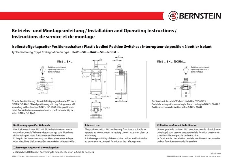
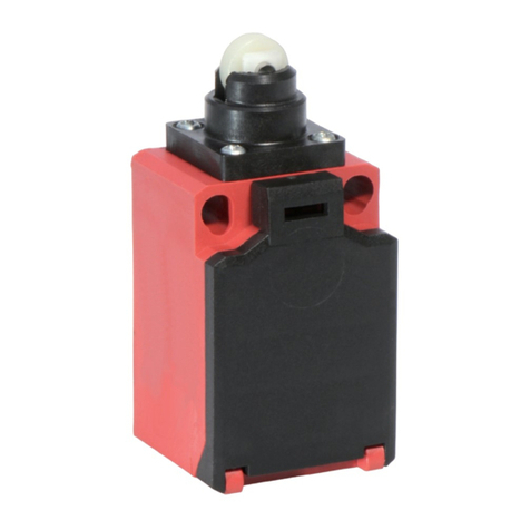
BERNSTEIN F1 Series User manual

Seite 1 von 28
BERNSTEIN AG . Hans-Bernstein-Straße 1 . 32457 Porta Westfalica . www.bernstein.eu Bernstein-Dok.: 0800000464 / Stand: 12 / 2021-11-04 / 2615-21
Fußschalter mit 1, 2 oder 3 Pedalen / Footswitches with 1, 2 or 3 pedals / Interrupteur à pédale avec 1, 2 ou 3 pédales
Typbezeichnung / Type / Désignation du type F...
Betriebs- und Montageanleitung / Installation and Operating Instructions /
Instructions de service et de montage

Seite 2 von 28
BERNSTEIN AG . Hans-Bernstein-Straße 1 . 32457 Porta Westfalica . www.bernstein.eu Bernstein-Dok.: 0800000464 / Stand: 12 / 2021-11-04 / 2615-21
Betriebs- und Montageanleitung / Installation and Operating Instructions / Instructions de service et de montage
Directory Sommaire
Installation and Operating instructions _______________ 2
Intended use ____________________________________ 3
Design _________________________________________ 3
Delivery specification _____________________________ 4
Function ________________________________________ 4
Identifying ______________________________________ 5
Year of manufacture_____________________________ 5
Product identification code_______________________ 5
Type designation and identification ________________ 7
Example ______________________________________ 9
Safety Instructions ________________________________ 9
Dimensions ____________________________________ 11
Installation _____________________________________ 12
Mechanical function test__________________________ 12
Electrical connection _____________________________ 12
Cover _________________________________________ 13
Switch insert, potentiometer, microswitch, button ___ 13
Analogue block _______________________________ 13
Contact element with enable function (ZS) ___________ 14
Electrical function test____________________________ 15
Safety function__________________________________ 15
Latching function (R) _____________________________ 15
Analogue block _________________________________ 16
Electrical Data __________________________________ 18
Mechanical Data ________________________________ 19
Note __________________________________________ 20
Safety application _______________________________ 20
ID for safety engineering__________________________ 20
Standards ______________________________________ 21
EU Conformity __________________________________ 21
Approvals ______________________________________ 21
Maintenance / Service ____________________________ 21
Cleaning / Disinfection ___________________________ 22
Liability Disclaimer_______________________________ 22
Declaration of Conformity_________________________ 24
Installation and Operating instructions
These installation and operating instructions are intended
for the machine builder, NOT the end user.
End user operating instructions must be made by the
machine builder.
Instructions de service et de montage ________________ 2
Utilisation conforme à la destination _________________ 3
Structure________________________________________ 3
Contenu de la livraison ____________________________ 4
Fonction ________________________________________ 4
Identification ____________________________________ 5
Année de fabrication ____________________________ 5
Identification par la référence _____________________ 5
Identification par la désignation ___________________ 8
Example ______________________________________ 9
Consignes de sécurité _____________________________ 9
Dimensions ____________________________________ 11
Montage_______________________________________ 12
Contrôle du fonctionnement montage ______________ 12
Raccordement électrique _________________________ 12
Couvercle ______________________________________ 13
Contacts, potentiomètre, micro-switch, boutons_____ 13
Bloc analogique _______________________________ 13
Elément de contact avec fonction de validation (ZS)____ 14
Contrôle du fonctionnement électrique______________ 15
Fonction de sécurité _____________________________ 15
Fonction de Verrouillage (R) _______________________ 15
Bloc analogique _________________________________ 16
Caractéristiques électriques _______________________ 18
Caractéristiques techniques _______________________ 19
Renseignement _________________________________ 20
Application de sécurité ___________________________ 20
Caractéristiques en matière de technique de la sécurité_ 20
Directives ______________________________________ 21
Conformité UE __________________________________ 21
Homologations _________________________________ 21
Entretien / Maintenance __________________________ 21
Nettoyage, désinfection __________________________ 22
Exclusion de la responsabilité ______________________ 22
Déclaration de Conformité ________________________ 24
Instructions de service et de montage
Ces instructions de service et de montage sont destinées au
fabricant de l’équipement et non à l’utilisateur final.
Le mode d’emploi pour l’utilisateur final doit être fait par le
fabricant du produit fini.
GB F
Inhaltsverzeichnis
D
Hinweise zur Betriebs- und Montageanleitung _________ 2
Bestimmungsgemäßer Gebrauch____________________ 3
Aufbau _________________________________________ 3
Lieferumfang ____________________________________ 4
Funktion ________________________________________ 4
Identifizierung ___________________________________ 5
Baujahr _______________________________________ 5
Identifizierung durch Artikelnummer _______________ 5
Identifizierung durch Typbezeichnung______________ 6
Beispiele ______________________________________ 9
Sicherheitshinweise_______________________________ 9
Abmessungen __________________________________ 11
Montage_______________________________________ 12
Mechanische Funktionsprüfung ____________________ 12
Elektrischer Anschluss ____________________________ 12
Deckel_________________________________________ 13
Schalteinsatz, Potentiometer, Mikroschalter, Taster ___ 13
Analogschaltmodul ____________________________ 13
Einbauschalter mit Zustimmfunktion________________ 14
Elektrische Funktionsprüfung ______________________ 15
Sicherheitsfunktion ______________________________ 15
Rastfunktion (R) _________________________________ 15
Analogschaltmodul ______________________________ 16
Elektrische Daten ________________________________ 18
Mechanische Daten ______________________________ 19
Hinweise_______________________________________ 20
Sicherheitsanwendung ___________________________ 20
Kennzahlen für Sicherheitstechnik __________________ 20
Vorschriften ____________________________________ 21
EU-Konformität _________________________________ 21
Zulassungen____________________________________ 21
Instandhaltung / Wartung_________________________ 21
Reinigung / Desinfektion__________________________ 22
Haftungsausschluss ______________________________ 22
Konformitätserklärung ___________________________ 24
Hinweise zur Betriebs- und Montageanleitung
Diese Betriebs- und Montageanleitung ist für den
Endproduktehersteller und nicht für den Endverbraucher
bestimmt. Die Erstellung einer Gebrauchsanweisung für
den Endverbraucher obliegt dem Endproduktehersteller.

Seite 3 von 28
BERNSTEIN AG . Hans-Bernstein-Straße 1 . 32457 Porta Westfalica . www.bernstein.eu Bernstein-Dok.: 0800000464 / Stand: 12 / 2021-11-04 / 2615-21
Die metallgekapselten Fußschalter werden zum Auslösen
einer Schaltfunktion mittels Fußbetätigung eingesetzt.
Die Fußschalter sind äußerst robust und somit für den
industriellen Einsatz ausgelegt.
Sie sind nicht als Untersatz für Geräte, Möbel oder andere
Gegenstände geeignet. Ebenso dürfen sie nicht als Tritt
verwendet werden.
1. Gehäuse
2. Pedal
3. Deckel / Unfall-Schutzhaube
4. Deckelschraube
5. Deckeldichtung
6. Einbauschalter
7. Erdungsschraube
8. Druckpunkt
9. Drucktaster
10. Not-Halt Taster
11. Etikett
12. Gummifuß
1. Enclosure
2. Pedal
3. Cover / Protective hood
4. Cover screw
5. Cover seal
6. Built-in switch
7. Earth bolt
8. Pressure point
9. Pushbuttons
10. Emergency Stop impact button
11. Label
12. Rubber foot
1. Boîtier
2. Pédale
3. Couvercle / Capot de protection
4. Vis du couvercle
5. Joint du couvercle
6. Interrupteur intégré
7. Vis de terre
8. Point de pression
9. Bouton
10. Touche d’arrêt d’urgence
11. Étiquette
12. Pied en caoutchouc
The metal encapsulated food switches are to be activated
by pressing the pedal.
The food switches are very sturdy and thus meet exacting
requirements in industrial applications.
They cannot be used under devices, furniture or other
objects. They also cannot be used as tread.
Les interrupteurs à pédale en boîtier métallique sont
déclenchés par l’actionnement de la pédale.
Les interrupteurs à pédale sont extrêmement robustes et
parfaitement adaptés aux exigences élevées des domaines
d’application industriels.
Ils ne peuvent pas être montés en dessous d’appareils,
de meubles ou d’autres objets. Ils ne doivent pas être utilisés
comme pas.
Bestimmungsgemäßer Gebrauch
Aufbau
Intended use
Design
Utilisation conforme à la destination
Structure
7
6
5
8
9
1
4
3
2
12
11
10

Seite 4 von 28
BERNSTEIN AG . Hans-Bernstein-Straße 1 . 32457 Porta Westfalica . www.bernstein.eu Bernstein-Dok.: 0800000464 / Stand: 12 / 2021-11-04 / 2615-21
Betriebs- und Montageanleitung / Installation and Operating Instructions / Instructions de service et de montage
Fußschalter, Betriebs- und Montageanleitung,
Verpackungsmaterial
bei montiertem Kabel: Zusatzhinweise Kabel
bei verdrahtetem Taster: Zusatzhinweise Taster
bei montierter oder beiliegender Kabelverschraubung:
Zusatzhinweise Kabelverschraubung
Der Anwender drückt das Pedal nach unten.
Diese abwärtsgerichtete Kraft wird umgesetzt und
betätigt die entsprechende Kontaktbestückung.
Pro Pedal besteht die Kontaktbestückung aus maximal
4 Schalteinsätzen oder 1 Potentiometer.
Die Schalteinsätze können Öffner, Schließer oder Wechsler
(mit Doppelunterbrechung) sein. Deren Ausführungen sind
entweder Sprung- oder Schleichschaltglieder.
Das Analogschaltmodul ist ein Reglerausgang mit einem
teachbaren Meldeausgang. Hier wird die Betätigung des
Pedals in ein Analogsignal und einen Schaltpunkt umgesetzt.
Der Schaltpunkt ist mit einer TEACH-Taste neu definierbar.
Zusätzlich besteht die Möglichkeit einen Druckpunkt einzubin-
den. Hierüber erhält der Anwender eine zusätzliche physische
Meldung über die Betätigungsstellung (taktile Rückmeldung).
Eine bistabile Schaltstellung ist ebenfalls wählbar. Hierbei wird
bei einmaliger Betätigung die Schaltstellung beibehalten und
erst bei einer weiteren Betätigung gelöst.
Je nach Ausführung hat der Fußschalter zusätzlich einen
Not-Halt Taster an der Oberseite des Gehäuses. Er wird durch
Fuß oder Hand betätigt.
Bei der Variante mit Sicherheitsrastung und Handentriegelung
gewährleistet der Fußschalter einen normalen Arbeitsablauf
und im Notfall eine sichere Abschaltung (kein Not-Halt im
Sinne der Norm DIN EN 60947-5-5).
Der Druckpunkt ist ein mechanischer Widerstand im
Betätigungsweg des Pedals. Die Betätigungskraft muss
deutlich ansteigen, um ihn zu überwinden.
Nach dem Überwinden gibt es eine Betätigungskraftsenke.
Footswitch, Installation and Operation Instructions,
Packaging material
with mounted cable: Additional note cable
with wired button: Additional note button
with mounted or enclosed cable gland:
Additional note cable gland
The user depresses the pedal. This downward force is
converted and operates the corresponding contact loadings.
For each pedal, the contact loading consists of a maximum of
4 switch inserts or 1 potentiometer.
The switch inserts can be NC, NO or double make double break
contacts. They are executed by a slow-action or snap-action
switch contact element.
The analogue block is a controller output with a teachable
signaling output. Here, the activation of the pedal is converted
into an analogue signal and a switching point. The switching
point can be redefined by the TEACH button.
It is also possible to integrate a pressure point, enabling the
user to receive additional physical feedback from the actuating
position (tactile feedback).
A bistable switch position is also available. Pressing once will
fix the switch position, and pressing again will release it.
Depending on the model, the foot switch may also have
an emergency stop button on the top of the enclosure, which
can be operated by foot or hand.
In the model with safety features and hand release, the foot
switch ensures normal operation and safe switch off in an
emergency (no emergency stop in the sense of the standard
DIN EN 60947-5-5).
The pressure point is a mechanical resistance in the pedal
travel. The operating force must increase significantly
to overcome this resistance. Once it has been overcome,
there is a reduction in the operating force.
Interrupteur à pédale, Instructions de service et de montage,
Matériau d’emballage
Avec câble monté : Renseignements supplémentaires câble
Avec bouton précablé : Renseignements supplément. bouton
Avec presse-étoupe monté ou en vrac :
Renseignements supplémentaires Presse-étoupe
L’utilisateur appuie de haut en bas sur la pédale. Cette force
dirigée vers le bas est convertie et elle actionne l’unité logique
correspondante.
L’unité logique se compose de 4 contacts ou d’un
potentiomètre par pédale.
Les contacts peuvent être normalement fermés, normalement
ouverts ou inverseurs (à double rupture). Ces contacts sont soit
à rupture brusque, soit à rupture lente.
Le bloc analogique est une sortie régulateur avec un signal de
sortie programmable. L’actionnement de la pédale est converti
en un signal analogique et un point de commutation. Le point
de commutation peut être redéfini par le bouton TEACH.
En outre, il est possible d’intégrer un point dur. Cela permet de
donner une indication physique supplémentaire sur la position
d’actionnement à l’utilisateur (retour tactile).
Il est également possible de choisir une position bistable.
Celle-ci permet de maintenir la position obtenue après
un premier actionnement et de ne la quitter qu’à l’occasion
d’un deuxième actionnement.
Selon la version, la pédale peut être équipée d’un bouton
d’arrêt d’urgence situé sur le dessus du capot. Il peut être
indifféremment actionné au pied ou à la main.
Avec variante équipée d’un cran de sécurité avec déverrouillage
manuel, le bloc pédale autorise un processus de travail normal
tout en garantissant un arrêt de sécurité en cas d’urgence (pas
d’arrêt d’urgence au sens de la norme DIN EN 60947-5-5).
Le point dur est constitué par une résistance mécanique dans
la course d’actionnement de la pédale. La force d’actionnement
doit nettement augmenter pour franchir ce point dur.
Après franchissement, la force d’actionnement diminue.
Lieferumfang
Funktion
Delivery specification
Function
Contenu de la livraison
Fonction

Seite 5 von 28
BERNSTEIN AG . Hans-Bernstein-Straße 1 . 32457 Porta Westfalica . www.bernstein.eu Bernstein-Dok.: 0800000464 / Stand: 12 / 2021-11-04 / 2615-21
Position des Etiketts: Grundsätzlich an der linken oder rechten
Seite des Gehäuses. Ausnahmen sind wegen Gehäusedurch-
brüchen, Anbauteilen oder durch Kundenwunsch möglich.
Identifizierung durch Artikelnummer
Die Artikelnummer des Fußschalters finden sie unterhalb der
Benennung auf dem Schalteretikett. Für die Korrespondenz
und Bestellungen bei der BERNSTEIN AG bitte diese Nummer
angeben.
Product identification code
The article number of the foot switch is located below the
designation on the product label. Please use this reference
when ordering or seeking information from BERNSTEIN AG.
Identification par la référence
La référence de l’interrupteur de sécurité à commande par câble
se trouve juste en dessous de la désignation sur l’étiquette de
l’interrupteur. Cette référence est à mentionner à la commande
ou sur toute correspondance adressée à BERNSTEIN AG.
Typbezeichnung / Type designation / Désignation du type
Fertigungsdatum / Date of manufacture / Date de fabrication
Artikelnummer / Article number / Référence
The label will generally be on the left or right side of the
enclosure. Alternative locations are possible if the enclosure
breaks, attachments are used, or if specified by the customer.
Position de la plaque signalétique : en principe sur le côté
gauche ou droit du boitier. Des exceptions sont possibles en
cas d’ouvertures dans le boitier ou à la demande du client.
Identifizierung Identifying Identification
04/2021

Seite 6 von 28
BERNSTEIN AG . Hans-Bernstein-Straße 1 . 32457 Porta Westfalica . www.bernstein.eu Bernstein-Dok.: 0800000464 / Stand: 12 / 2021-11-04 / 2615-21
Betriebs- und Montageanleitung / Installation and Operating Instructions / Instructions de service et de montage
Identifizierung durch Typbezeichnung
F2-U1ZA2ZDR/SU1ZCA2ZDR FS UN _ _
Kontaktbestückung und Ausstattung pro Pedal
Die Reihenfolge der Kontakteinsätze (K1, K2, K3, K4, K5, K6): siehe Bild rechts. Die Kontakteinsätze unterschiedlicher Pedale (P1, P2, P3)
werden durch einen schrägen Strich (/) getrennt wenn ein Trennsteg vorhanden ist. Ohne Trennsteg werden sie durch einen
Bindestrich (-) getrennt. Die Schaltfunktion besteht aus mindestens 1 und maximal 2 Kontaktbestückung oder 1 Reglerausgang pro Pedal.
Gleichwertige Kontakteinsätze werden pro Pedal in Kurzform angegeben.
Beispiele: 2 x U1 = U2, 2 x U1Z = U2Z, 2 x UV1Z = UV2Z, 2 x SU1 = SU2, 2 x SU1Z = SU2Z, 2 x SUV1Z = SUV2Z, 2 x A2 = A4, 2 x A2Z = A4Z
siehe Seite 9
Schalterfamilie
F1 = 1-pedalig
F2 = 2-pedalig
F3 = 3-pedalig
Schaltfunktionen
Kontakt-
bestückung Schließer Öner Sprung-
funktion
Schleich-
funktion
Zwangs-
önung
beim Schließen
verzög. Öner
Form Zb
U1 1x 1x
Schalteinsatz
U1Z 1x 1x
UV1 1x 1x
UV1Z 1x 1x
SU1 1x 1x
SU1Z 1x 1x
A1 1x
A2 2x
A1Z 1x
A2Z 2x
SA2 2x
E1 1x
E2 2x
SE2 2x
RG Reglerausgang
AI4-20mA Analogschaltmodul, Stromausgang 4 – 20 mA
AI0-20mA Analogschaltmodul, Stromausgang 0 – 20 mA
AU0-5V Analogschaltmodul, Spannungsausgang 0 – 5 V
AU0-10V Analogschaltmodul, Spannungsausgang 0 – 10 V
ZS 2x 1x Einbauschalter mit Zustimmfunktion (ZS) nach DIN EN 60947-5-8
ZSP1 2x 1x ZS mit PNP Zusatzplatine zur Dierenzierung der Stellung 1 *
ZSP3 2x 1x ZS mit PNP Zusatzplatine zur Dierenzierung der Stellung 3 *
ASI-ZS 2x 1x ASI„safety at work“ Anbindung mit ZS
ASI-ZSP1 2x 1x ASI-ZS mit PNP Zusatzplatine zur Dierenzierung der Stellung 1 *
ASI-ZSP3 2x 1x ASI-ZS mit PNP Zusatzplatine zur Dierenzierung der Stellung 3 *
Ohne Zeichen vor der
Schaltfunktion =
Standardeinbauschalter
der Fußschalterbaureihe.
Mit„C“ vor der Schaltfunk-
tion = Einbauschalter für
spezielle Schaltfunktionen
* Zusatzplatine: keine Sicherheits-
funktion, nur für Meldezwecke
Ausstattung
D = Druckpunkt, Y = Rastschaltung (ohne Zwangsönung), R = Rastung (Es können max. 2 Pedale mit der Rastung vorhanden sein.), RG = Reglerausgang, ES = Elektronischer Schalteinsatz,
PS = Pedalschutz (gesperrtes Pedal), AT = Anti-Trip Funktion. Schutz gegen nicht gewolltes Betätigen, Überh = Schaltet nach dem Druckpunkt die Hubfunktion im Einbauschalter zurück.
Vorhandene Ausstattungen sind in alphabetischer Reihenfolge aufzuführen.
K2 K4 K6
K1 K3 K5
P1 P2 P3

Seite 7 von 28
BERNSTEIN AG . Hans-Bernstein-Straße 1 . 32457 Porta Westfalica . www.bernstein.eu Bernstein-Dok.: 0800000464 / Stand: 12 / 2021-11-04 / 2615-21
Type designation and identification
F2-U1ZA2ZDR/SU1ZCA2ZDR FS UN _ _
Contact configuration and equipment of each pedal
The arrangement of the contact configurations (K1, K2, K3, K4, K5, K6): see figure on the right. The contact elements of different
pedals (P1, P2, P3) are separated by a diagonal slash (/) when a separator is provided. Without separator, they are separated by a hyphen (-).
The switching function consists of at least 1 and a maximum of 2 contact configuration or 1 regulator outlet per pedal. Equivalent contact
configurations of each pedal are indicated in short form.
Examples: 2 x U1 = U2, 2 x U1Z = U2Z, 2 x UV1Z = UV2Z, 2 x SU1 = SU2, 2 x SU1Z = SU2Z, 2 x SUV1Z = SUV2Z, 2 x A2 = A4, 2 x A2Z = A4Z
see page 9
Switching functions
Switch familiy
F1 = 1-pedal
F2 = 2-pedal
F3 = 3-pedal
Contact
configuration
Normally-
open contact
Normally-
closed contact
Snap-action
function
Slow-action
function
Positive open
action
Norm.-closed con-
tact with del. open. Form Zb
U1 1x 1x
built-in switch
U1Z 1x 1x
UV1 1x 1x
UV1Z 1x 1x
SU1 1x 1x
SU1Z 1x 1x
A1 1x
A2 2x
A1Z 1x
A2Z 2x
SA2 2x
E1 1x
E2 2x
SE2 2x
RG Controller output
AI4-20mA Analogue block, current output 4 – 20 mA
AI0-20mA Analogue block, current output 0 – 20 mA
AU0-5V Analogue block, voltage output 0 – 5 V
AU0-10V Analogue block, voltage output 0 – 10 V
ZS 2x 1x Contact element with enable function (ZS) acc. to DIN EN 60947-5-8
ZSP1 2x 1x ZS with PNP additional board for the dierentiation of position 1 *
ZSP3 2x 1x ZS with PNP additional board for the dierentiation of position 3 *
ASI-ZS 2x 1x ASI“safety at work”Connection with ZS
ASI-ZSP1 2x 1x
ASI-ZS with PNP additional board for the dierentiation of position 1 *
ASI-ZSP3 2x 1x
ASI-ZS with PNP additional board for the dierentiation of position 3 *
In case of no sign in
front of the switching
function = standard
built-in switch of the
foot switches range.
“C”in front of the
switching function =
built-in switch
for special switching
functions.
* Additional board: not a
security feature, only for
signalling purposes
Equipement
D = Pressure point, Y = Latch-action switching (without positive open action), R = Latching (Locking data will be provided once the pedal is equipped with the locking function.
A maximum of 2 pedals can use the locking function), RG = Controller output, ES = Electronical built-in switch, PS = Pedal protection (blocked pedal), AT = Pedal lock function.
Protection against unintentional actuation. Uberh = the stroke function in the built-in switch is reactivated after actuating the pressure point.
K2 K4 K6
K1 K3 K5
P1 P2 P3

Seite 8 von 28
BERNSTEIN AG . Hans-Bernstein-Straße 1 . 32457 Porta Westfalica . www.bernstein.eu Bernstein-Dok.: 0800000464 / Stand: 12 / 2021-11-04 / 2615-21
Betriebs- und Montageanleitung / Installation and Operating Instructions / Instructions de service et de montage
Identification par la désignation
F2-U1ZA2ZDR/SU1ZCA2ZDR FS UN _ _
Equipement des contacts et de chaque pédale
L’ordre des équipements des contacts (K1, K2, K3, K4, K5, K6) : voir plan à droite. Les éléments de contact de différentes pédales (P1, P2, P3)
sont séparés par une diagonale oblique (/) lorsqu’un cloisonnement est prévu. Ils sont séparés par un tiret (-) sans cloisonnement.
Par pédale, la fonction de commutation se compose au minimum d’un équipement des contacts et de 2 au maximum ou d’une sortie de
régulation. Les contacts de même valeur sont indiqués en abrégé pour chaque pédale.
Des exemples : 2 x U1 = U2, 2 x U1Z = U2Z, 2 x UV1Z = UV2Z, 2 x SU1 = SU2, 2 x SU1Z = SU2Z, 2 x SUV1Z = SUV2Z, 2 x A2 = A4, 2 x A2Z = A4Z
regardez à la page 9
Gamme
d’interrupteur :
F1 = 1 pédale
F2 = 2 pédales
F3 = 3 pédales
Fonctions de commutation
Equipement
des contacts
Contact norma-
lement ouvert
Contact norma-
lement fermé
Contact à
rupture brusque
Contact à
rupture lente
D’ouverture
forcée
Contacts NF à
ouvert. temporisée Forme Zb
U1 1x 1x
Interrupteur intégré
U1Z 1x 1x
UV1 1x 1x
UV1Z 1x 1x
SU1 1x 1x
SU1Z 1x 1x
A1 1x
A2 2x
A1Z 1x
A2Z 2x
SA2 2x
E1 1x
E2 2x
SE2 2x
RG Sortie de régulateur
AI4-20mA Bloc analogique, sortie courant 4 – 20 mA
AI0-20mA Bloc analogique, sortie courant 0 – 20 mA
AU0-5V Bloc analogique, sortie tension 0 – 5 V
AU0-10V Bloc analogique, sortie tension 0 – 10 V
ZS 2x 1x
Elément d. contact avec fonct. d. validation (ZS) suivant DIN EN 60947-5-8
ZSP1 2x 1x ZS avec carte supplémentaire PNP p. la di. de la position 1 *
ZSP3 2x 1x ZS avec carte supplémentaire PNP p. la di. de la position 3 *
ASI-ZS 2x 1x ASI « safety at work » Connexion avec ZS
ASI-ZSP1 2x 1x ASI-ZS avec carte supplémentaire PNP p. la di. de la position 1 *
ASI-ZSP3 2x 1x ASI-ZS avec carte supplémentaire PNP p. la di. de la position 3 *
K2 K4 K6
K1 K3 K5
P1 P2 P3
Sans signe avant la
fonction de commu-
tation = interrupteur
intégré standard faisant
partie du programme
d’interrupteurs à pédale
Avec «C» devant la fonc-
tion de commutation
= Elément de contact
pour les fonctions de
commutation spéciales.
* Carte supplémentaire :
aucune fonction de
sécurité, seulement pour
signalisation
Équipement
D = Point de pression, Y = Commutation pas à pas (sans ouverture forcée), R = Verrouillage (L’indication du cran est précisée dès lors que la pédale est équipée de cette fonction. Il ne peut y
avoir que 2 pédales qui soient équipées d’un cran), RG = sortie de régulateur, ES = Interrupteur intégré électronique, PS = Protection de la pédale (pédale bloquée), AT = Verrouillage de pédale.
Protection contre l’actionnement non voulu. Überh = la fonction de course dans l’interrupteur intégré est réactivé après l’actionnement du point de pression.

Seite 9 von 28
BERNSTEIN AG . Hans-Bernstein-Straße 1 . 32457 Porta Westfalica . www.bernstein.eu Bernstein-Dok.: 0800000464 / Stand: 12 / 2021-11-04 / 2615-21
F2-U1ZA2ZDR/SU1ZCA2ZDR FS UN _ _
Zusatzfunktionen pro Fußschalter / Additional functions of each foot switch /
Fonctions supplémentaires par interrupteur à pédale
FS = Fußstütze / Foot rest / Repose-pieds
NA2 = Not-Aus-Taster / Emergency Stop button / Touche d’arrêt d’urgence
LS22= Leistungsschütz / Power contactor / Dispositif de protection de puissance intégré
Sicherheitsausrüstung pro Fußschalter / Safety equipment for each foot switch /
Equipement de sécurité par interrupteur à pédale
UN = Unfallschutzhaube / Die-cast protective hood / Capot de protection
UK = Klappbare UN-Haube / Hinged protective hood / Capot de protection rabattable
Eine Kombination von Zustimmschalter und Haube ist nicht vorgesehen. /
A combination of enable switch and hood is not provided. /
Une combinaison de l’interrupteur et du capot n’est pas prévue.
siehe Seite 6 / see page 7 / regardez à la page 8
F2- U1ZA2ZDR/SU1ZCA2ZDR FS UN
- Fußschalter, 2-pedalig
- Pedal 1: Standardeinbauschalter: 1 x Wechsel
(Schleichfunktion, Zwangsöffnung), Standardeinbauschalter:
2 x Öffner (Schleichfunktion, Zwangsöffnung), Druckpunkt;
ein Schalter mit Rastung
- Trennsteg zwischen Pedal 1 und Pedal 2
- Pedal 2: Standardeinbauschalter: 1 x Wechsel (Sprung-
schalter, Zwangsöffnung), Einbauschalter: 2 x Öffner
(Schleichfunktion, Zwangsöffnung), Druckpunkt; ein Schalter
mit Rastung
- mit Fußstütze ausgestattet.
- Schaltgerät mit Unfallschutzhaube.
F2- U1ZA2ZDR/SU1ZCA2ZDR FS UN
- Foot switch, 2-pedals
- Pedal 1: Standard built-in switch: 1 x Change over contact
(slow-action function, positive open action), standard built-in
switch: 2 x NC (slow-action function, positive open action),
pressure point; a switch with latch function
- Separator between pedal 1 and pedal 2
- Standard built-in switch: 1 x Change over contact
(slow-action function, positive open action), standard built-in
switch: 2 x NC (slow-action function, positive open action),
pressure point; a switch with latch function
- Equiped with footrest.
- Switching device with die-cast protective hood.
F2- U1ZA2ZDR/SU1ZCA2ZDR FS UN
- Interrupteur à pédale, 2 pédales
- Pédale 1 : Interrupteur intégré standard : 1 x inverseur
(contact à rupture lente, d’ouverture forcée), interrupteur
intégré standard : 2 x NF (contact à rupture lente, d’ouverture
forcée), point de pression; l’interrupteur avec verrouillage
- Cloisonnement entre pédale 1 et pédale 2
- Pédale 2 : Interrupteur intégré : 1 x inverseur (contact à
rupture lente, d’ouverture forcée), interrupteur intégré : 2 x NF
(contact à rupture lente, d’ouverture forcée), point de pression
- Une combinaison d’interrupteur intégré avec la possibilité
de verrouillage en position actionnée; l’interrupteur avec
verrouillage
- Equipé de repose-pieds.
- Dispositif de commutation avec capot de protection.
Beispiel Example Example
Der Fußschalter darf nur auf festem, ebenem Untergrund
eingesetzt werden.
Der Untergrund muss frei von Stoffen sein, die ein Rutschen
oder Gleiten des Schalters begünstigen. Oder er muss fest
installiert sein.
The foot switch can only be used on solid, level surfaces.
The surface must be free of substances that could cause the
switch to slip or slide. If not, its position must be fixed.
Le bloc pédale doit impérativement être posé sur un support
ferme et plan.
Celui-ci doit être libre de tout élément pouvant faire glisser ou
ripper le bloc pédale. Sinon, le bloc doit être fixé.
Sicherheitshinweise Safety Instructions Consignes de sécurité

Seite 10 von 28
BERNSTEIN AG . Hans-Bernstein-Straße 1 . 32457 Porta Westfalica . www.bernstein.eu Bernstein-Dok.: 0800000464 / Stand: 12 / 2021-11-04 / 2615-21
Betriebs- und Montageanleitung / Installation and Operating Instructions / Instructions de service et de montage
Der Fußschalter muss frei zugänglich sein. Es muss sichergestellt
sein, dass er nicht an eine unzugängliche Position geschoben
werden kann (z. B. unter eine Maschine oder Möbel).
Die Bedienteile des Fußschalters müssen von der üblichen
Arbeitsposition des Bedieners leicht erreichbar sein.
Bei Bedienung des Fußschalters darf der Bediener nicht in eine
gefahrbringende Position geraten.
Die Anordnung von Fußschalter und Anschluss muss so erfol-
gen, dass daraus keine Behinderungen oder Gefahrenquellen
entstehen (z. B. Stolpergefahr, Be- oder Verhinderung beim
Öffnen von Notausgängen, Türen, Klappen, …).
Die Funktion der Bedienelemente (Fußpedal(e) und Taster)
muss sichergestellt sein. Sie dürfen nicht verkleben, verharzen,
festgestellt oder blockiert werden (gewollte oder ungewollte
Manipulation).
Der Fußschalter und dessen Anschluss müssen vor nicht
bestimmungsgemäßer Beanspruchung (z. B. überrollen,
betreten, quetschen, klemmen, …) geschützt werden.
Der Fußschalter darf nicht am Anschlusskabel transportiert
oder gezogen werden.
Vor Arbeiten an der Elektrik sind die Strom führenden Teile
spannungsfrei zu schalten.
Der Fußschalter ist ausschließlich für stationäre Anwendungen
konzipiert. Schock- und Schwingbeanspruchungen, z. B. durch
Stürze oder Tritte, können den Schaltvorgang unbeabsichtigt
auslösen.
Sobald mehrere Schalter mit Zustimmfunktion oder Schalter
mit und ohne Zustimmfunktion kombiniert werden ist eine
Verwechslung der Funktionen auszuschließen. Dies kann zum
Beispiel durch steuerungstechnische Maßnahmen erfolgen.
Der Anwender hat die verbleibenden Restrisiken zu beurteilen
und zu dokumentieren (gemäß ISO 13849-2, Validierung).
Elektromechanische Zustimmschalter/-einrichtungen sind
so mit der Steuerung zu verknüpfen, dass die Anforderungen
an Stromkreise, die der Sicherheit dienen gemäß
DIN EN ISO 10218-1, DIN EN 60204-1, DIN EN ISO 13849-1
und DIN EN ISO 1161, sowie VDI 2854 erfüllt sind.
Mit Zustimmschaltern allein dürfen keine Steuersignale
für Gefahr bringende Zustände eingeleitet werden
(siehe EN 60204-1, Abs. 9.2.6.3).
The foot switch must be freely accessible. Ensure that the
switch cannot accidentally be pushed into an inaccessible
position (e.g. under a machine or furniture).
The operating units of the foot pedal must be easily accessible
from the operator’s usual working position.
When operating the foot switch, the operator must not fall
into a dangerous position.
The foot switch and the connection must be positioned so
that they do not form an obstruction or present a safety
hazard (e.g. a risk of tripping, or hindering or preventing the
opening of emergency exits, doors, hatches, etc.)
It must be ensured that control elements (foot pedal(s)
and buttons) function correctly. They should not stick
to each other, become gummy, lock or jam (deliberate or
non-deliberate manipulation).
The foot switch and its connection must be protected from
unintended stress (e.g. being rolled over, kicking, squashing,
jamming, etc.)
Do not carry or drag the foot pedal by its connecting cable.
Before working on the electrical parts, the live parts must be
disconnected from the mains.
The foot switch is exclusively designed for stationary
applications. Shock and vibration stress, e.g. due to falls or
kicks, can inadvertently trigger the switching process.
If multiple switches with enable function or switches with or
without enable function are combined, a mix of function must
be excluded. This can be done for example through control
measures.
The user has to assess and document the residual risks
(according to ISO 13849-2, validation).
Electromechanical enable switches/installations are to
be linked to the control unit in that way that the require-
ments according to DIN EN ISO 10218-1, DIN EN 60204-1,
DIN EN ISO 13849-1 and DIN EN ISO 1161, as well as
VDI 2854 for circuits which serve as security are fulfilled.
The introduction of control signals for unsafe
conditions should not only be made via the enable switch
(see EN 60204-1, par. 9.2.6.3).
Le bloc pédale doit être facilement accessible. Il doit être pris
garde qu’il ne puisse être repoussé dans un endroit inaccessible
(p. ex. sous une machine ou sous un meuble).
Les unités opérationnelles de l’interrupteur à pédale doivent être
facilement accessibles à partir de la position habituelle de travail
de l’opérateur.
Lors de l’utilisation de l’interrupteur à pédale, il faut s’assurer que
l’opérateur ne se met pas en danger.
L’implantation du bloc pédale et de son cordon de raccordement
doit être réalisée de sorte à ce qu’ils n’occasionnent pas de gène
et ne présent pas de source de danger (p. ex. faire trébucher les
personnes ou entraver l’ouverture d’issues de secours, de portes
ou de fenêtres etc.).
Le bon fonctionnement des éléments de commande (pédales et
boutons) doit être assuré. Ils ne doivent en aucun cas être collés,
noyés dans la résine, entravés ou bloqués (volontairement ou non).
Le bloc pédale et son cordon de raccordement doivent être
protégés contre les sollicitations non conformes à sa destination
(p. ex. en roulant ou en marchant dessus, par écrasement ou par
pincement).
Le bloc pédale ne doit jamais être tiré ni transporté par son cordon
de raccordement.
Les pièces conductrices doivent être mises hors tension avant
d’entreprendre toute intervention sur le circuit électrique.
L’interrupteur à pédale est exclusivement conçu pour les
applications stationnaires. Les chocs et contraintes de vibrations,
tels que chutes ou coups de pieds, peuvent par inadvertance
déclencher le processus de commutation.
Dans le cas où plusieurs interrupteurs à pédale dotés d’une fonc-
tion de validation ou des interrupteurs avec ou sans fonction de
validation sont combinés, un mélange des fonctions doit être exclu.
Cela peut être fait par exemple à travers des mesures de contrôle.
L’utilisateur doit évaluer et documenter les risques résiduels
(suivant ISO 13849-2, validation).
Les interrupteurs de validation électromécaniques sont à relier à
l’unité de contrôle de façon à ce que les exigences, suivant
DIN EN ISO 10218-1, DIN EN 60204-1, DIN EN ISO 13849-1 et
DIN EN ISO 1161, VDI 2854 y inclus, en matière de circuits
servant de sécurité soient remplies.
L’interrupteur de validation ne peut être utilisé à lui
seul pour contrôler des signaux de commandes de danger
(voir EN 60204-1, par. 9.2.6.3).

Seite 11 von 28
BERNSTEIN AG . Hans-Bernstein-Straße 1 . 32457 Porta Westfalica . www.bernstein.eu Bernstein-Dok.: 0800000464 / Stand: 12 / 2021-11-04 / 2615-21
F1 F2
Abmessungen Dimensions Dimensions
F3

Seite 12 von 28
BERNSTEIN AG . Hans-Bernstein-Straße 1 . 32457 Porta Westfalica . www.bernstein.eu Bernstein-Dok.: 0800000464 / Stand: 12 / 2021-11-04 / 2615-21
Betriebs- und Montageanleitung / Installation and Operating Instructions / Instructions de service et de montage
Die Montage darf nur durch autorisiertes Fachpersonal erfolgen.
Sofern der Fußschalter nicht fixiert werden soll, ist kein Werk-
zeug erforderlich.
Beachten Sie die für Ihren speziellen Anwendungsfall vorge-
sehenen Normen, Vorschriften und Anweisungen.
Im Allgemeinen sind die Sicherheitshinweise (siehe Seite 9)
zu beachten.
Die Montage beschränkt sich auf das Aufstellen des Fußschal-
ters. Die Gummifüße (siehe Bild auf Seite 3) müssen auf festen,
ebenen und rutschfesten Untergrund stehen.
Der Fußschalter kann durch die Bohrungen Ø 8,5 mm fixiert
werden. Hierbei beachten Sie bitte, dass die Funktion des
Pedals nicht beeinträchtigt wird.
Die mechanische Funktionsprüfung erfolgt durch
Betätigung der Bedienelemente (Fußpedal(e)) und,
falls vorhanden Taster.
Der Fußschalter muss einwandfrei bedienbar sein.
Der elektrische Anschluss darf nur durch autorisiertes
Fachpersonal erfolgen.
Stellen Sie sicher, dass der Fußschalter vor Öffnen des
Deckels spannungsfrei ist.
Notwendiges Werkzeug
Schraubendreher
Kreuzschlitzschraubendreher Pz2
(oder Schlitzschraubendreher 1x6) für Deckel, UN-Haube,
Schalteinsätze und Schutzleiteranschluss
Schlitzschraubendreher 0,5x3 mm für Klemmleiste(n)
Installation should only be carried out by authorised technical
personnel.
Tools are not required.
Refer to standards, requirements and instructions applicable
to your specific application.
The safety instructions (see page 9) must be observed at all
times.
Installation is restricted to placing the foot switch
in the required position. The rubber feet (see illustration on
page 3) must be placed on a firm, flat and non-slip surface.
The foot switch can be fixed through the Ø 8.5 mm holes.
Please note that the function of the pedal is not affected.
The mechanical function check involves operating the
controls (foot pedal(s)) and pushbutton if fitted.
The foot-operated switch must be fully functional at all times.
Only authorised, qualified personnel may carry out
the electrical connection.
Ensure that the foot switch is not live before opening
the cover.
Required tool
Screwdriver
Pz2 crosshead screwdriver (or 1x6 standard screwdriver) for
cover, protective hood, built-in switch and earth conductor
0.5 x 3 mm standard screwdriver for terminal strip(s)
Uniquement un personnel spécialisé agréé est autorisé à
procéder au montage de l’interrupteur à pédale(s).
Aucun outil n’est nécessaire.
Tenir compte des normes, directives et instructions prévues
pour votre application particulière.
Il convient de respecter en général les consignes de sécurité
(voir page 9).
Le montage se limite à l’installation de l’interrupteur à
pédale(s). Les pieds en caoutchouc (voir fig. à la page
3) doivent être posés sur une surface plane, solide et
antidérapante.
L’interrupteur à pédales peut être fixé par les trous de Ø 8,5
mm. Veuillez noter que la fonction de la pédale n’est pas
affectée.
Procéder au contrôle du fonctionnement mécanique
en actionnant les éléments de commande (pédale(s)) et,
si présent, le bouton-poussoir.
Il doit être possible d’utiliser sans le moindre problème
l’interrupteur à pédale(s).
Le raccordement électrique doit être exclusivement
réalisé par un électricien professionnel agréé.
Assurez-vous que le bloc pédale est hors tension avant
d’ouvrir le couvercle.
Outil nécessaire
Tournevis
Tournevis cruciforme Pz2 (ou tournevis plat 1 x 6) pour
le couvercle, le capot, les contacts et le raccordement du
conducteur de mise à la terre
Tournevis plat 0,5 x 3 pour le(s) bornier(s)
Montage
Mechanische Funktionsprüfung
Elektrischer Anschluss
Installation
Mechanical function test
Electrical connection
Montage
Contrôle du fonctionnement montage
Raccordement électrique

Seite 13 von 28
BERNSTEIN AG . Hans-Bernstein-Straße 1 . 32457 Porta Westfalica . www.bernstein.eu Bernstein-Dok.: 0800000464 / Stand: 12 / 2021-11-04 / 2615-21
Deckel Cover Couvercle
Deckel
Cover
Couvercle
(F1 und F2 mit Rastnasen am Deckel)
Zu beachten:
Beschädigen oder verunreinigen Sie die Teile nicht, ansonsten
ist die Schutzart nicht mehr gewährleistet.
Ausbau:
Lösen Sie die Deckelschrauben.
Anzahl der Schrauben je nach Modell.
(F1 = 1Schraube, F2 = 2Schrauben und F3 = 4Schrauben)
Heben Sie den Deckel (Unfallschutzhaube) rechtwinklig ab.
Einbau:
Umgekehrte Reihenfolge, wie Ausbau. Anzugsmoment der
Deckelschrauben: 2 Nm.
(F1 and F2 with latches on the cover)
Please note:
Ensure that the parts are clean and do not become damaged,
otherwise the level of protection is reduced.
Disassembly:
Loosen the cover screw(s).
Number of screws per model.
(F1 = 1 screw, F2 = 2 screws and F3 = 4 screws)
Open the cover (protective hood) at a right angle.
Assembly:
As disassembly, but in reverse order. Tightening torque of the
cover screw(s): 2 Nm.
(F1 et F2 : tournevis à ergot pour le couvercle)
Attention :
Ne pas endommager ni salir les pièces car cela pourrait
entrainer la perte du degré de protection.
Ouverture :
Dévisser les vis du couvercle.
Leur nombre est fonction du modèle.
(F1 = 1 vis, F2 = 2 vis et F3 = 4 vis)
Basculer le couvercle (le capot anti-accident) à angle droit.
Fermeture :
Effectuer les opérations dans l'ordre inverse de l'ouverture.
Couple de serrage des vis du couvercle : 2 Nm.
Schalteinsatz, Potentiometer, Mikroschalter, Taster
Switch insert, potentiometer, microswitch, button
Contacts, potentiomètre, micro-switch, boutons
Lösen Sie die zur Verdrahtung notwendigen Schrauben.
Führen Sie die Verdrahtung durch und ziehen Sie die
Schrauben mit folgenden Anzugsmomenten fest:
Schalteinsatz 0,7 – 0,8 Nm
Klemmleiste(n) 0,2 Nm
Remove any screws required for wiring.
Carry out the wiring and tighten the screws with the following
tightening torques:
Switch insert 0.7 –0.8 Nm
Terminal strip(s) 0.2 Nm
Dévisser les vis nécessaires pour effectuer les raccordements.
Réaliser le branchement en serrant les vis au couple suivant :
Contact de 0,7 à 0,8 Nm
Bornier(s) 0,2 Nm
Analogschaltmodul Analogue block Bloc analogique
Zur Einhaltung der EMV-Richtlinie (2004/108/EC) muss eine
geschirmte Anschlussleitung verwendet werden.
To be conform with the EMV guideline (2004/108/EC) a
shielded connection cable has to be used.
Pour être conforme à la directive EMV (2004/108/EC), un câble
blindé est nécessaire.
BERNSTEIN-Dok.: 0800000464.doc / Stand : 5/ Ausgabedatum : 15.10.2014 / 2564-14 Blatt 13 von 24
Vorlage : 0850174292 Orig. 2
(F1 und F2 mit Rastnasen am Deckel)
Zu beachten:
Beschädigen oder verunreinigen Sie die Teile nicht,
ansonsten ist die Schutzart nicht mehr gewährleistet.
Ausbau:
Lösen Sie die Deckelschrauben. Anzahl der Schrauben
je nach Modell. (F1 = 1 Schraube, F2 = 2 Schrauben und
F3 = 4 Schrauben)
Heben Sie den Deckel (Unfallschutzhaube) rechtwinklig ab.
Einbau:
Umgekehrte Reihenfolge, wie Ausbau. Anzugsmoment der
Deckelschrauben: 2 Nm.
Schalteinsatz, Potentiometer, Mikroschalter, Taster
Lösen Sie die zur Verdrahtung notwendigen Schrauben.
Führen Sie die Verdrahtung durch und ziehen Sie
die Schrauben mit folgenden Anzugsmomenten fest:
Schalteinsatz 0,7 – 0,8 Nm
Klemmleiste(n) 0,2 Nm
Analogschaltmodul
Zur Einhaltung der EMV-Richtlinie (2014/30/EU) muss eine
geschirmte Anschlussleitung verwendet werden.
(F1 and F2 with latches on the cover)
Please note:
Ensure that the parts are clean and do not become damaged,
otherwise the level of protection is reduced.
Disassembly:
Loosen the cover screw(s). Number of screws per model.
(F1 = 1 screw, F2 = 2 screws and F3 = 4 screws)
Open the cover (protective hood) at a right angle.
Assembly:
As disassembly, but in reverse order. Tightening torque of the
cover screw(s): 2 Nm.
Switch insert, potentiometer, microswitch, button
Remove any screws required for wiring.
Carry out the wiring and tighten the screws with the following
tightening torques:
Switch insert 0.7 – 0.8 Nm
Terminal strip(s) 0.2 Nm
Analogue block
To be conform with the EMC-Directive (2014/30/EU)
a shielded connection cable has to be used.
(F1 et F2 : tournevis à ergot pour le couvercle)
Attention :
Ne pas endommager ni salir les pièces car cela pourrait
entrainer la perte du degré de protection.
Ouverture :
Dévisser les vis du couvercle. Leur nombre est fonction du
modèle. (F1 = 1 vis, F2 = 2 vis et F3 = 4 vis)
Basculer le couvercle (le capot anti-accident) à angle droit.
Fermeture :
Effectuer les opérations dans l’ordre inverse de l’ouverture.
Couple de serrage des vis du couvercle : 2 Nm.
Contacts, potentiomètre, micro-switch, boutons
Dévisser les vis nécessaires pour effectuer les raccordements.
Réaliser le branchement en serrant les vis au couple suivant :
Contact de 0,7 à 0,8 Nm
Bornier(s) 0,2 Nm
Bloc analogique
Pour être conforme à la directive EMV (2014/30/EU),
un câble blindé est nécessaire.

Seite 14 von 28
BERNSTEIN AG . Hans-Bernstein-Straße 1 . 32457 Porta Westfalica . www.bernstein.eu Bernstein-Dok.: 0800000464 / Stand: 12 / 2021-11-04 / 2615-21
Betriebs- und Montageanleitung / Installation and Operating Instructions / Instructions de service et de montage
Einbauschalter mit Zustimmfunktion (ZS) Contact element with enable function (ZS) Elément de contact avec fonction de validation (ZS)
Ein
ON
Marche
Aus
OFF
Arrêt
Einbauschalter mit Zustimmfunktion (ZS) Contact element with enable function (ZS) Elément de contact avec fonction de validation (ZS)
11 –12 Öffner / Normally-closed contact / Contact normalement fermé
23 –24 Schließer / Normally-open contact / Contact normalement ouvert
33 –34 Schließer / Normally-open contact / Contact normalement ouvert
Hub/Stroke/Course Kraft/Force/Force
1. Stellung/Position/Position
2. Stellung/Position/Position
Druckpunkt/Pressure point/Point de pression
3Stellung/Position/Position Toleranz / Tolerance / Tolérance± 10 %
Zu beachten:
Die Anschlussleitungen müssen so ausgelegt und die
Komponenten so verdrahtet sein, dass kein Bauteil geklemmt
oder gequetscht wird. Entfernen Sie alle Fremdkörper, wie z.B.
Abisolierungen, Werkzeuge, Schrauben, etc., aus dem
Schalterinnern.
Deckel, Deckeldichtung und Gehäuse dürfen nicht beschädigt
oder verunreinigt sein. Der Deckel darf nicht beim Einsetzen
verkantet werden. Ansonsten ist die Schutzart nicht mehr
gewährleistet.
Positionieren Sie den Deckel korrekt.
Ziehen Sie alle Deckelschrauben mit 2 Nm fest.
Anzahl der Deckelschrauben siehe oben.
Please note:
The connecting cables must be laid out and the components
wired in such a way that no component can be jammed or
squashed. Remove all foreign bodies such as stripped parts,
tools, screws, etc. from the interior of the switches.
Ensure that the cover, cover seal and enclosure are clean and
do not become damaged. The cover should not be tilted when
in use, as this can reduce the level of protection.
The cover must be in the correct position.
Fasten all cover screws with 2 Nm.
For the number of screws, see above.
Attention:
Le câblage des composants doit être effectué de sorte à éviter
tout risque d'écrasement ou de pincement des différents
éléments. Enlevez tout corps étranger, p. ex. isolant, outils, vis
etc. de l'intérieur du bloc.
Le couvercle, son joint et le boîtier ne doivent être ni
endommagés ni encrassés. Le couvercle ne doit pas être
refermé de travers. Cela pourrait entrainer la perte du degré de
protection.
Positionnez correctement le couvercle.
Serrer toutes les vis du couvercle à 2 Nm.
Nombre de vis du capot : voir plus haut.
24
34
12
23
33
11
BERNSTEIN-Dok.: 0800000464.doc / Stand : 5/ Ausgabedatum : 15.10.2014 / 2564-14 Blatt 14 von 24
Vorlage : 0850174292 Orig. 2
11 – 12 Öffner / Normally-closed contact / Contact normalement fermé
23 – 24 Schließer / Normally-open contact / Contact normalement ouvert
33 – 34 Schließer / Normally-open contact / Contact normalement ouvert
Ein
ON
Marche
Aus
OFF
Arrêt
Einbauschalter mit Zustimmfunktion (ZS) Contact element with enable function (ZS) Elément de contact avec fonction de validation (ZS)
11 –12 Öffner / Normally-closed contact / Contact normalement fermé
23 –24 Schließer / Normally-open contact / Contact normalement ouvert
33 –34 Schließer / Normally-open contact / Contact normalement ouvert
Hub/Stroke/Course Kraft/Force/Force
1. Stellung/Position/Position
2. Stellung/Position/Position
Druckpunkt/Pressure point/Point de pression
3Stellung/Position/Position Toleranz / Tolerance / Tolérance± 10 %
Zu beachten:
Die Anschlussleitungen müssen so ausgelegt und die
Komponenten so verdrahtet sein, dass kein Bauteil geklemmt
oder gequetscht wird. Entfernen Sie alle Fremdkörper, wie z.B.
Abisolierungen, Werkzeuge, Schrauben, etc., aus dem
Schalterinnern.
Deckel, Deckeldichtung und Gehäuse dürfen nicht beschädigt
oder verunreinigt sein. Der Deckel darf nicht beim Einsetzen
verkantet werden. Ansonsten ist die Schutzart nicht mehr
gewährleistet.
Positionieren Sie den Deckel korrekt.
Ziehen Sie alle Deckelschrauben mit 2 Nm fest.
Anzahl der Deckelschrauben siehe oben.
Please note:
The connecting cables must be laid out and the components
wired in such a way that no component can be jammed or
squashed. Remove all foreign bodies such as stripped parts,
tools, screws, etc. from the interior of the switches.
Ensure that the cover, cover seal and enclosure are clean and
do not become damaged. The cover should not be tilted when
in use, as this can reduce the level of protection.
The cover must be in the correct position.
Fasten all cover screws with 2 Nm.
For the number of screws, see above.
Attention:
Le câblage des composants doit être effectué de sorte à éviter
tout risque d'écrasement ou de pincement des différents
éléments. Enlevez tout corps étranger, p. ex. isolant, outils, vis
etc. de l'intérieur du bloc.
Le couvercle, son joint et le boîtier ne doivent être ni
endommagés ni encrassés. Le couvercle ne doit pas être
refermé de travers. Cela pourrait entrainer la perte du degré de
protection.
Positionnez correctement le couvercle.
Serrer toutes les vis du couvercle à 2 Nm.
Nombre de vis du capot : voir plus haut.
24
34
12
23
33
11
BERNSTEIN-Dok.: 0800000464.doc / Stand : 5/ Ausgabedatum : 15.10.2014 / 2564-14 Blatt 14 von 24
Vorlage : 0850174292 Orig. 2
Hub/Stroke/Course Kraft/Force/Force
Toleranz/Tolerance/Tolérance ± 10 %
Ein
ON
Marche
Aus
OFF
Arrêt
[mm]
1. Stellung/Position/Position
2. Stellung/Position/Position
3. Stellung/Position/Position
Druckpunkt/Pressure point/Point de pression
[N]
>10
25
200
Zu beachten:
Die Anschlussleitungen müssen so ausgelegt und die
Komponenten so verdrahtet sein, dass kein Bauteil geklemmt
oder gequetscht wird. Entfernen Sie alle Fremdkörper,
wie z. B. Abisolierungen, Werkzeuge, Schrauben, etc., aus
dem Schalterinnern.
Deckel, Deckeldichtung und Gehäuse dürfen nicht beschädigt
oder verunreinigt sein. Der Deckel darf nicht beim Einsetzen
verkantet werden. Ansonsten ist die Schutzart nicht mehr
gewährleistet.
Positionieren Sie den Deckel korrekt.
Ziehen Sie alle Deckelschrauben mit 2 Nm fest.
Anzahl der Deckelschrauben siehe oben.
Please note:
The connecting cables must be laid out and the components
wired in such a way that no component can be jammed or
squashed. Remove all foreign bodies such as stripped parts,
tools, screws, etc. from the interior of the switches.
Ensure that the cover, cover seal and enclosure are clean and
do not become damaged. The cover should not be tilted when
in use, as this can reduce the level of protection.
The cover must be in the correct position.
Fasten all cover screws with 2 Nm.
For the number of screws, see above.
Attention :
Le câblage des composants doit être effectué de sorte à éviter
tout risque d’écrasement ou de pincement des différents
éléments. Enlevez tout corps étranger, p. ex. isolant, outils,
vis etc. de l’intérieur du bloc.
Le couvercle, son joint et le boîtier ne doivent être ni endom-
magés ni encrassés. Le couvercle ne doit pas être refermé de
travers. Cela pourrait entrainer la perte du degré de protection.
Positionnez correctement le couvercle.
Serrer toutes les vis du couvercle à 2 Nm.
Nombre de vis du capot : voir plus haut.

Seite 15 von 28
BERNSTEIN AG . Hans-Bernstein-Straße 1 . 32457 Porta Westfalica . www.bernstein.eu Bernstein-Dok.: 0800000464 / Stand: 12 / 2021-11-04 / 2615-21
Schließen Sie den Fußschalter an Ihr System an.
Überprüfen Sie Ihre Schaltfunktionen durch Betätigung der
Bedienelemente des Fußschalters.
Bei Fehlfunktionen schalten Sie den Fußschalter spannungsfrei.
Beseitigen Sie den Fehler und beginnen Sie erneut mit der
Überprüfung.
Nicht alle Fußschalter haben eine Rastfunktion. Diejenigen mit
Rastfunktion haben ein„R“ in der Typbezeichnung.
Ein Halten des erreichten Schaltzustandes ist nur bei Schaltern
mit Rastfunktion gegeben.
Eine Entriegelung erfolgt nur durch Drücken der blauen
Entriegelungstaste. Diese befindet sich an der Gehäuseseite
des Fußschalters.
1. Betätigung des Pedals bis zum Druckpunkt:
Der Arbeitskontakt ist geschlossen, der Arbeitsprozess
eingeleitet.
2. In einer Notsituation Betätigung über den Widerstand des
Druckpunktes hinaus:
Der Arbeitskontakt ist unterbrochen und verriegelt, der
Arbeitsprozess unterbrochen. Auch bei Nichtbetätigen des
Pedals bleibt in dieser Phase die Verriegelung in Aus-Stellung
erhalten. Ein unkontrolliertes Wiederanlaufen oder ein neuer
Start beweglicher Maschinenteile wird so sicher vermieden.
3. Entriegelung:
Erst nach Beseitigung der gefahrbringenden Situation gibt
eine Entriegelung von Hand (blaue Drucktaste am Gehäuse)
die Kontakte wieder frei; der Arbeitskontakt kann durch
Betätigung des Pedals bis zum Druckpunkt erneut eingelei-
tet werden.
Connect the foot switch to your system.
Check the switch function by pressing the control element
of the foot switch.
If a malfunction occurs, disconnect the foot switch from the
mains.
Rectify the fault and check the foot switch aigain.
Not all foot switches have an Emergency Latching
Function. Those with a latching function have“R”in the
type designation.
Holding the reached switching status is only possible for
switches with latching function.
A reset is only possible by pressing the blue release button.
This is located on the housing side of the foot switch.
1. Depress the pedal until it reaches the pressure point:
the normally open contact is closed and the work process is
initiated.
2. In an emergency, apply an amount of pressure that exceeds
the resistance of the pressure point:
The normally open contact will be interrupted and locked,
thus interrupting the work process. Even if the pedal is not
depressed, the locking mechanism will remain in the OFF
position in this phase. This ensures that parts will not start
moving again.
3. Unlocking:
Once the dangerous situation has been rectified, unlocking
by hand (the blue button on the enclosure) will release
the contacts again, and the normally open contact can be
reinitiated by depressing the pedal until it reaches the
pressure point.
Raccordez le bloc pédale à votre système.
Vérifiez vos fonctions de commutation en actionnant les
éléments de commande du bloc.
En cas de dysfonctionnement, mettez le bloc pédale hors
tension.
Éliminez le défaut et recommencez les vérifications.
Les interrupteurs à pédale ne sont pas tous dotés d’un
maintien du verrouillage. Ceux qui disposent d’un maintien
du verrouillage ont « R » dans la désignation.
L’état de commutation atteint ne peut être tenu que si vous
utilisez des interrupteurs doté d’un maintien du verrouillage.
Une réinitialisation est uniquement possible en appuyant
sur le bouton bleu de déverrouillage. Ceci est situé sur le côté
du boîtier de l’interrupteur à pédale.
1. Actionnement de la pédale jusqu’au point dur :
le contact de travail est fermé le processus de travail est
engagé.
2. En cas d’urgence, actionnement au-delà de la résistance
du point dur :
Le contact de travail est ouvert et verrouillé, le processus de
travail est interrompu. Pendant cette phase, le verrouillage
en position Arrêt reste maintenu, même si la pédale n’est
plus actionnée. Cela permet d’éviter en toute sécurité que la
machine ne redémarre ou que ses éléments ne se remettent
en mouvement de manière incontrôlée.
3. Déverrouillage :
Une fois la situation dangereuse éliminée, il est possible de
déverrouiller les contacts manuellement (à l’aide du bouton
bleu du boîtier) ; Le contact de travail peut de nouveau être
activé en appuyant sur la pédale jusqu’au point dur.
Elektrische Funktionsprüfung
Rastfunktion (R)
Sicherheitsfunktion (F...ZSDR...)
Electrical function test
Latching function (R)
Safety function (F...ZSDR...)
Contrôle du fonctionnement électrique
Fonction de Verrouillage (R)
Fonction de sécurité (F...ZSDR...)

Seite 16 von 28
BERNSTEIN AG . Hans-Bernstein-Straße 1 . 32457 Porta Westfalica . www.bernstein.eu Bernstein-Dok.: 0800000464 / Stand: 12 / 2021-11-04 / 2615-21
Betriebs- und Montageanleitung / Installation and Operating Instructions / Instructions de service et de montage
Schaltpunkt festlegen
Der Schaltpunkt ist im Auslieferzustand nicht definiert und
liegt im Bereich des Betätigungsweges (6 mm) zwischen
0,1 und 5,9 mm. Der Schaltpunkt kann beliebig oft festgelegt
werden. Dazu den Stoßbolzen auf die gewünschte Position
(Betätigungsweg) drücken, diese Position halten und
TEACH -Taste betätigen. Der Stoßbolzen kann jetzt wieder
freigegeben werden. Der Schaltausgang signalisiert
mit fünfmaligem Schalten den erfolgreichen Lernvorgang.
Bei weiteren Betätigungen schaltet das Analogmodul bei
dem eingelernten Schaltpunkt.
To determine the switching point
The switching point is not determined when delivered and is
centred in the range of the actuation travel (6 mm) between
0,1 and 5,9 mm. The switching point can be adjusted to at any
point within the travel range. You simply press the impact pin
to the desired position (within the actuation travel), maintain
this position and actuate the TEACH button. The impact pin
can now be released again. The switching output signals after
five switching operations the successful learning process.
For further actuations, the analogue block switches at the
learned-in switching point.
Déterminer le point de commutation
Le point de commutation n’est pas déterminé lors
de la livraison. Il est centré dans la plage de la course
d’actionnement (6 mm) entre 0,1 et 5,9 mm.
Le point de commutation peut être réglé à n’importe quel
point dans la plage de la course d’actionnement. Veuillez
simplement appuyer sur le poussoir jusqu’à la position désirée
(course d’actionnement), tenir cette position et actionner
sur le bouton TEACH. Le succès de l’apprentissage est confirmé
par 5 commutations de la sortie.
La commutation se fait au point défini pour chaque
commutation ultérieure.
Analogschaltmodul
(AI4-20mA, AI0-20mA, AU0-5V, AU0-10V)
Analogue block
(AI4-20mA, AI0-20mA, AU0-5V, AU0-10V)
Bloc analogique
(AI4-20mA, AI0-20mA, AU0-5V, AU0-10V)

Seite 17 von 28
BERNSTEIN AG . Hans-Bernstein-Straße 1 . 32457 Porta Westfalica . www.bernstein.eu Bernstein-Dok.: 0800000464 / Stand: 12 / 2021-11-04 / 2615-21
Schalteinsatz, Reglerausgang (ohne Teachfunktion), Built-in switch, Controller output (without Teach function), Interrupteur intégré, Sortie de régulateur
Einbauschalter mit Zustimmfunktion Contact element with enable function (sans fonction d’enseignement), Elément de contact
avec fonction de validation
Bemessungsisolationsspannung / Rated isolation voltage /
Tension assignée d’isolement Ui
400 V AC
250 V AC (in Typbezeichnung„ZS“)
400 V AC
250 V AC (in type designation“ZS”)
400 V AC
250 V AC (dans la désignation « ZS »)
Bemessungsstoßspannungsfestigkeit /
Rated impulse withstand voltage /
Tension assignée de tenue aux chocs
Uimp
4 kV *
2,5 kV (in Typbezeichnung„C“,„ZS“) *
* gilt nicht für„RG“ in Typbezeichnung
4 kV *
2,5 kV (in type designation“C”,“ZS”) *
* not applicable for“RG” in type designation
4 kV *
2,5 kV (dans la désignation « C »,« ZS ») *
*ne s’applique pas aux «RG » dans la désignation
Konv. thermischer Strom / Conventional thermal current /
Courant thermique conv. Ithe
10 A
5 A (in Typbezeichnung„ZS“)
10 A
5 A (in type designation“ZS”)
10 A
5 A (dans la désignation « ZS »)
Gebrauchskategorie / Utilization category / Catégorie d’usage
AC-15, Ue/ Ie240 V / 3 A
AC-15, Ue / Ie 240 V / 1,5 A (in Typ-
bezeichnung„ZS“)
AC-15, Ue/ Ie240 V / 3 A
AC-15, Ue / Ie 240 V / 1,5 A (in type
designation“ZS”)
AC-15, Ue/ Ie240 V / 3 A
AC-15, Ue / Ie 240 V / 1,5 A (dans la
désignation « ZS »)
Zwangsönung / Direct opening action /
Manoeuvre positive d’ouverture nach IEC/EN 60947-5-1, Anhang K
(bei Erreichen des Pedalanschlags)
as per IEC/EN 60947-5-1, Addendum
(on reaching the pedal stop)
selon la norme CEI/EN 60947-5-1,
(en atteignant la butée de la pédale)
Bedingter Kurzschlussstrom / Conditional short circuit current /
Courant assigné de court-circuit conditionnel
1000 A
nach DIN EN 60947-5-1
1000 A
as per DIN EN 60947-5-1
1000 A
selon la norme DIN EN 60947-5-1
Kurzschlussschutzeinrichtung / Short circuit protection /
Protection contre court-circuit
Schmelzsicherung 10 A gG
(Schleichschaltglieder)
Schmelzsicherung 2A gG
(Sprungschaltglieder / Mikroschalter)
D-Sicherung 4A gG (Einbauschalter
mit Zustimmfunktion)
Schmelzsicherung F 50 mA
(Potentiometer)
Fuse 10 A gG
(slow-action contacts)
Fuse 2A gG
(snap-action contact / microswitch)
D-Fuse 4A gG (Built-in switch with
enable function)
Fuse F 50 mA
(potentiometer)
fusible 10 A gG
(contacts à rupture lente)
fusible 2A gG (contacts à
rupture brusque / microrupteur)
D-Fusible 4A gG (Interrupteur intégré
fonction de validation)
fusible F 50 mA
(potentiomètre)
Überspannungskategorie
(Einbauschalter mit Zustimmfunktion) /
Overvoltage category (buil-in switch with enable function) /
Catégorie de surtension
(interrupteur intégré avec fonction de validation)
III (nach IEC 60664-1) III (as per IEC 60664-1) III (selon la norme IEC 60664-1)
Elektrische Daten Electrical Data Caractéristiques électriques
Schutzklasse / Protection class / Degré de protection I (Schutzklasse III bei Zeichen auf
dem Schalteretikett)
I(Protection class III with sign on the
switch label)
I(Degré de protection III avec le signe
sur l‘étiquette de l‘interrupteur)

Seite 18 von 28
BERNSTEIN AG . Hans-Bernstein-Straße 1 . 32457 Porta Westfalica . www.bernstein.eu Bernstein-Dok.: 0800000464 / Stand: 12 / 2021-11-04 / 2615-21
Betriebs- und Montageanleitung / Installation and Operating Instructions / Instructions de service et de montage
Analogschaltmodul / Analogue block / Bloc analogique
Bemessungsbetriebsspannungsbereich / Rated operating
voltage range / Plage de tension nominale de fonctionnement UB12–26 V DC 12–26 V DC 12–26 V DC
Analogausgang / Analogue output / Sortie analogique je nach Typ
(0–5 V; 0–10 V; 0–20 mA; 4–20 mA)
depending on the type
(0–5 V; 0–10 V; 0–20 mA; 4–20 mA)
selon type
(0–5 V; 0–10 V; 0–20 mA; 4–20 mA)
Linearitätsfehler / Linearity errors / Erreurs de linéarité ≤ ± 2,5 % vom Endwert,
UBund Temperatur konstant
≤ ± 2,5 % from the end value,
UBand temperature at a constant level
≤ ± 2,5 % de la valeur finale,
UBet température à un niveau constant
Temperaturfehler / Temperature errors / Erreurs de température ≤ ± 10 % UBkonstant ≤ ± 10 % UBat a constant level ≤ ± 10 % UBà un niveau constant
Wiederholgenauigkeit / Repetition accuracy /
Précision de répétition R≤ 2 % vom Endwert,
UBund Temperatur konstant
≤ 2 % from the end value,
UBand temperature at a constant level
≤ 2 % de la valeur finale,
UBet température à un niveau constant
Schaltausgang / Switching output / Sortie de commutation S PNP Schließer; (teachbar) PNP NO; (teachable) PNP NO; (enseignable)
Hysterese / Hysteresis / Hystérésis H ≈ 10 % ≈ 10 % ≈ 10 %
Leerlaufstrom / Idle current / Consommation de courant lo< 25 mA < 25 mA < 25 mA
Spannungsfall / Voltage drop/ Chute de tension Ud≤ 1,6 V ≤ 1,6 V ≤ 1,6 V
Gebrauchskategorie / Utilization category / Catégorie d’emploi DC 12 DC 12 DC 12
Bemessungsbetriebsstrom / Rated operational currents /
Courants assignés d’emploi le200 mA 200 mA 200 mA
Kleinster Betriebsstrom (Schaltelement) / Minimum
operating current (Switching element) / Courant minimum
de fonctionnement (Elément de commutation)
Im1 mA 1 mA 1 mA
Reststrom / Residual current / Courant résiduel lr< 0,1mA < 0,1mA < 0,1mA
max. Bürdewiderstand / Maximum load impedance /
Impédance de charge maximale RB400 Ω 400 Ω 400 Ω
Analogausgang / Analogue output / Sortie analogique dauerkurzschluss- u. überlastfest permanently short-circuit and overload
protected
protection permanente contre les
courts-circuits et contre les surcharges
Schaltelement / Switching element / Elément de commutation dauerkurzschluss- u. überlastfest permanently short-circuit and overload
protected
protection permanente contre les
courts-circuits et contre les surcharges
Art des Kurzschlussschutzes / Short-circuit protection type /
Type de protection contre les courts-circuits Taktend Synchronising Synchronisation
Schalthäugkeit / Switching frequency /
Fréquence de commutation max. 100/min. max. 100/min. max. 100/min.
Verpolschutz / Reverse polarity / Inversions de polarité ja yes oui
Bereitschaftsverzug / Readiness delay / Retard à la disponibilité tv< 50 ms < 50 ms < 50 ms

Seite 19 von 28
BERNSTEIN AG . Hans-Bernstein-Straße 1 . 32457 Porta Westfalica . www.bernstein.eu Bernstein-Dok.: 0800000464 / Stand: 12 / 2021-11-04 / 2615-21
Elektromagnetische Verträglichkeit (EMV)1) / Electromagnetic compatibility (EMC)1) / Compatibilité électromagnétique (EMC)1) – Analogschaltmodul
Störfestigkeit gegen die Entladung statischer Elektrizität / Immunity to Electrostatic Discharge /
Immunité aux décharges électrostatiques IEC 61000-4-2 (nur im eingebauten Zustand) / (only in installed
condition) / (uniquement à l’état monté)
Störfestigkeit gegen hochfrequente elektromagnetische Felder / Interference resistance against high-frequency
electromagnetic fields / Immunité aux champs électromagnétiques rayonnés aux fréquences radioélectriques IEC 61000-4-3
Störfestigkeit gegen schnelle transiente elektrische Störgrößen (Burst) /
Immnity to fast transient interference variables (bursts) / Immunité transistoires en salves IEC 61000-4-4
Störfestigkeit gegen leitungsgeführte Störgrößen, induziert durch hochfrequente Felder / Immunity to conducted interference
induced by radio frequency fields / Imunité aux perturbations conduites, induites par les champs radioélectriques IEC 61000-4-6
Störfestigkeit gegen Magnetfelder mit energietechnischen Frequenzen / Immunity against magnetic fields with power
frequency / Immunité aux champs magnétiques avec fréquence de régime IEC 61000-4-8
Leitungsgeführte Störgrößen/Störspannung/Störstrom / Conducted disturbances/Interference voltage /
Interference currents / Perturbations conduites/Tension parasite/Courants d’interférences EN 55011 class B
Gestrahlte Störgrößen/elektrische Feldstärke / Radiated disturbances/electric field strength /
Perturbations rayonnées/Intensité de champ électrique EN 55011 class B
1) Zur Einhaltung der EMV-Richtlinie (2014/30/EU) muss eine geschirmte Anschlussleitung verwendet werden. /
To be conform with the EMC-Directive (2014/30/EU) a shielded connection cable has to be used. / Pour être conforme à la directive EMV (2014/30/EU) , un câble blindé est nécessaire.
Mechanische Daten Mechanical Data Caractéristiques techniques
Gehäuse / Enclosure / Boîtier Aluminiumguss (pulverbeschichtet) Aluminium casting (powder-coated) Fonte d’aluminium (revêtu par poudre)
Deckel , UN-Haube / Cover, Protective shroud UN /
Couvercle, Capot de protection UN Aluminiumguss (pulverbeschichtet) Aluminium casting (powder-coated) Fonte d’aluminium (revêtu par poudre)
Betätigung / Actuator / Commande Fußhebel (Thermoplast) Foot pedal (thermoplastic) Pédale (plastique thermodurcissable)
Umgebungstemperatur (keine Vereisung / keine Kondensation) /
Ambient temperature (no freezing over/no condensation)
Température ambiante (aucun givrage/ aucune condensation)
–30°C bis +80°C –30 °C to +80 °C –30 °C à +80 °C
Lagertemperatur / Storage temperature / Température de stockage -30°C bis +80°C -30 °C to +80 °C -30 °C à +80 °C
Mechanische Lebensdauer / Mechanical life / Durée de vie mécanique > 1x10⁶Schaltspiele > 1x10⁶switching operations > 1x10⁶cycles de manoeuvre
Schalthäufigkeit / Switching frequency / Nombre d’opérations 50 min–1 50 min–1 50 tr/min
Anschlussart / Connection / Type de raccordement Schraubanschlüsse (M3,5) Screw connections (M3.5) Raccords filetés (M3,5)
Leiterquerschnitte / Conductor cross sections /
Sections des conducteurs
Eindrähtig 0,5 – 1,5 mm² oder Litze mit
Aderendhülse 0,5 – 1,5 mm²
Single-wire 0.5 – 1.5 mm² or Stranded wire
with wire end ferrule 0,5 – 1,5 mm²
Unifilaire 0,5 à 1,5 mm² ou Toron avec
embout 0,5 à 1,5 mm²

Seite 20 von 28
BERNSTEIN AG . Hans-Bernstein-Straße 1 . 32457 Porta Westfalica . www.bernstein.eu Bernstein-Dok.: 0800000464 / Stand: 12 / 2021-11-04 / 2615-21
Betriebs- und Montageanleitung / Installation and Operating Instructions / Instructions de service et de montage
Werden Schaltgeräte hintereinander geschaltet, dann
wird der Performance Level nach DIN EN 13849-1 reduziert.
Der Grund ist eine verringerte Fehlererkennung.
Nur Schaltgeräte mit Zwangsöffnung nach IEC/EN 60947-5-1,
Anhang K und gleichzeitiger Prüfung durch eine zertifizierte
Stelle (z. B. DGUV) erfüllen die Maschinenrichtlinie 2006/42/EG.
Sie sind gekennzeichnet durch für die Zwangsöffnung und
einen Zertifikatsaufkleber (z. B.„DGUV Test“).
Nur diese Schaltgeräte sind für den Einsatz in elektrischen
Stromkreisen mit Sicherheitsanwendungen geeignet.
Schließerkontakte alleine dürfen nicht in den Sicherheitskreis
eingebunden sein.
If switching devices are switched on after each other, the
performance level will be reduced pursuant to EN 13849-1,
which is due to reduced error detection.
Only switching devices with positive open action according
to IEC/EN 60947-5-1, annex K, and simultaneous testing by a
certified body (e.g. DGUV) comply with the Machinery Directi-
ve 2006/42/EC.
They are marked by for positive opening and a certificate
sticker (e.g.„DGUV Test“).
These are the only switching devices that are suitable for use in
electrical circuits with safety applications.
Make contacts alone must not be included in the safety circuit.
Si les appareils de commande sont raccordés l’un après
l’autre, le niveau de performance se réduit selon DIN EN 13849-1.
La raison en est une plus faible détection de défaut.
Seuls les appareillages de commutation à ouverture positi-
ve selon la norme CEI/EN 60947-5-1, annexe K, et les essais
simultanés effectués par un organisme certifié (par exemple, la
DGUV) sont conformes à la directive sur les machines
2006/42/CE.
Ils sont marqués par une ouverture positive et un autocol-
lant de certificat (par exemple,„DGUV Test“).
Seuls ces appareils de commutation peuvent être utilisés dans
des circuits électriques avec des applications de sécurité.
Les contacts à fermeture seuls ne doivent pas être inclus dans
le circuit de sécurité.
Hinweis
Sicherheitsanwendung
Note
Safety application
Renseignement
Application de sécurité
1) bei / @ / à DC-13; 24 V; Ie2 = 0,1 A
2) Sobald eine Einschränkung vorliegt, gilt der niedrigste Wert / In the case of restriction, the lowest value shall apply / En cas de restriction, la valeur la plus basse s’applique
Mechanische Daten Mechanical Data Caractéristiques techniques
Kabeleinführung / Cable entrance / Mise en place du câble M20x1,5 M20x1,5 M20x1,5
Gewicht mit Deckel / Weight with cover / Poids avec couvercle F1 ≈ 0,6 kg, F2 ≈ 1,7 kg, F3 ≈ 3,0 kg F1 ≈ 0,6 kg, F2 ≈ 1,7 kg, F3 ≈ 3,0 kg F1 ≈ 0,6 kg, F2 ≈ 1,7 kg, F3 ≈ 3,0 kg
Gewicht mit UN-Haube / Weight with protective shroud UN /
Poids avec capot de protection UN F1 ≈ 1,5 kg, F2 ≈ 2,6 kg, F3 ≈ 5,4 kg F1 ≈ 1,5 kg, F2 ≈ 2,6 kg, F3 ≈ 5,4 kg F1 ≈ 1,5 kg, F2 ≈ 2,6 kg, F3 ≈ 5,4 kg
Schutzart / Protection type / Degré de protection siehe Etikett see label voir étiquette
Kennzahlen für funktionale Sicherheit Characteristics for functional safety Caractéristiques de la sécurité fonctionnelle
B10d 1) 20 x 106
6 x 10⁶Einschränkungen in Typbezeichnung„C“ 2) Limitations in type designation “C” 2) Limites dans la désignation « C » 2)
2 x 10⁶Einschränkungen in Typbezeichnung„D“ 2) Limitations in type designation “D” 2) Limites dans la désignation « D » 2)
10 x 106Einschränkungen in Typbezeichnung„ZSD“
Abfolge der Schaltstellung 1,2,1 2)
Limitations in type designation“ZSD”
Sequence of the switching position 1,2,1 2)
Limites dans la désignation « ZSD »
Séquence de positions de commutation 1,2,1 2)
1 x 10⁶Einschränkungen in Typbezeichnung„ZSD“
Abfolge der Schaltstellung 1,2, 3,1 2)
Limitations in type designation“ZSD”
Sequence of the switching position 1,2, 3,1 2)
Limites dans la désignation « ZSD »
Séquence de positions de commutation 1,2, 3,1 2)
1 x 10⁵Einschränkungen in Typbezeichnung„ZSDR“
Abfolge der Schaltstellung 1,2, 3,1 2)
Limitations in type designation“ZSDR”
Sequence of the switching position 1,2, 3,1 2)
Limites dans la désignation « ZSDR»
Séquence de positions de commutation 1,2, 3,1 2)
This manual suits for next models
3
Table of contents
Other BERNSTEIN Switch manuals
Popular Switch manuals by other brands

UTAH SCIENTIFIC
UTAH SCIENTIFIC Utah-400 iP System setup and operations
Elko
Elko iNels RFSA-166M quick start guide
Siemens
Siemens SIMATIC NET SCALANCE X005 Commissioning manual

Huawei
Huawei Quidway S3528 Series instruction manual
Linear Technology
Linear Technology DC2251A Demo Manual

HP
HP StorageWorks 8/24 specification
