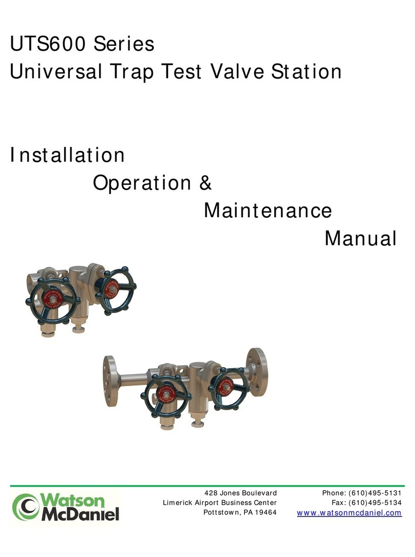
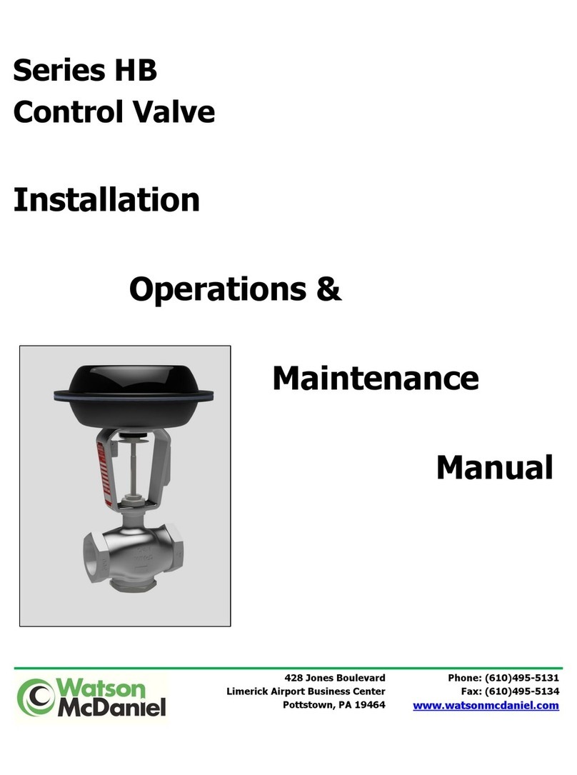
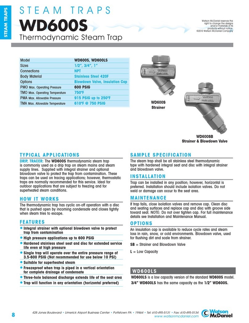
Watson McDaniel HSP Series Instruction Manual

Series HSP
Pressure Pilot Regulating Valve
Installation
Operations &
Maintenance
Manual
428 Jones Boulevard
Limerick Airport Business Center
Pottstown, PA 19464
Phone: (610)495-5131
Fax: (610)495-5134
www.watsonmcdaniel.com

2
Watson McDaniel Company HSP Valve Manual Rev3 2415800
HSP Specifications
Figure 1: HS Pressure Regulating Valve
Item Description
I Pilot Assembly
II
Main Valve Assembly
HSP Valve Pressure-Temperature Ratings
150# Flanges 150psi @ 566°F
300# Flanges 450psi @ 650°F
Pressure Adjusting Range for Pilot Spring
Pressure Color
5-40 PSIG Yellow
25-100 PSIG Blue
75-300 PSIG
Red
Note: Y, B, or R is indicated on the pilot at
the adjustment screw to provide the pressure
reducing spring range
Size Flange Face to Face B C* D E** F Weight
(lb)
150PSI 300PSI
1 5 1/2 6 6 11/32 6 11/16 7 1/8 6 23/32 0.12 45
1 1/2 6 7/8 7 3/8 7 9/16 6 13/16 9 7 7/16 0.152 60
2 8 1/2 9 8 1/4 7 10 7/8 7 5/8 0.178 95
3 10 10 3/4 8 7/8 7 13 3/4 8 5/8 0.25 160
4 11 7/8 12 1/2 10 7/8 7 14 3/4 9 3/4 0.299 245
All dimensions are in inches unless noted differently
* With Pilot Screw at max height and applying no load to Spring
** Based on approximate position of plug
Each Watson McDaniel Company Product is warranted against defects in material and workmanship for one year from date of shipment. This warranty extends to
the first retail purchaser only. All defective material must be returned to the person from whom you purchased the Product, transportation prepaid, free of any
liens or encumbrances, and if found to be defective will be repaired free of charge or replaced, at the warrantor’s or seller’s option. If the material is replaced, any
replacement will be invoiced in the usual manner and after inspection of alleged defective material an adjustment will be made for depreciation caused by
purchaser’s use. In no event will Watson McDaniel Company be liable to do more than refund the original contract price. Incidental and consequential damages
are excluded, whether under this warranty or otherwise. All implied warranties, including warranties of merchantability and fitness for a particular purpose, are
disclaimed and excluded.
I
II
Do not insulate
below line

3
Watson McDaniel Company HSP Valve Manual Rev3 2415800
Principle of Operation
The HSP Pilot Operated Pressure Regulating Valve
is designed to maintain a consistent downstream
pressure for steam applications.
1. High pressure steam enters the Main Valve
Body and fills the chamber above the Seat in
the main body.
2. The high pressure steam moves to the Pilot
Base where a stainless steel screen captures
unwanted dirt and particles. This allows
cleaner steam to pass through to the pilot base.
3. Turning the Pilot Adjusting Screw clockwise
compresses the Adjusting Spring. The Adjusting
Spring applies pressure to the Pilot Diaphragm
which opens the Pilot Valve.
4. The steam then travels through the Pilot Valve
to the External Transmission Tubing. This then
fills the area under the Main Valve Diaphragm.
5. The pressure under the Main Valve
Diaphragm pushes the stem upward which
lifts the Main Valve Disc off the Seat, which
allows the upstream steam to flow to the
downstream piping.
6. The Pilot Sensing Line, which is
recommended to be a minimum of 10 pipe
diameters downstream from the valve, also
fills with steam. The steam then builds
pressure under the Pilot Diaphragm to
balance the spring force and allow the Pilot to
throttle to maintain a constant downstream
pressure.
7. When the valve must close, the Bleed Orifice
will allow pressure to exit the area under the
Main Valve Diaphragm and into the
downstream piping
1
2
3
4
5
6

4
Watson McDaniel Company HSP Valve Manual Rev3 2415800
Figure 2: Valve Operations
Installation
ARecommended Notes for System
1. Piping will need to be adequately sized to
handle the flow, velocity, and pressure
requirements for the regulator’s application.
2. Piping upstream should generally be 1-2X
larger and downstream should be 2-3X
larger than the valve to eliminate flow
restrictions.
3. An eccentric reducer at inlets will reduce the
risk of water hammer by removing a
potential condensate collection point.
4. To prevent condensate from possibly
damaging the regulator or pipe, an
adequately sized drip leg with steam trap
should be installed prior to the regulator.
5. A strainer with blow down valve is
recommended before all regulator
installations. The strainer should be in the
horizontal position to prevent any collection
of condensate. Pipeline debris and scale
can damage internal valve components,
potentially leading to poor operation and/or
failure.
6. A bypass line may be added with gate
valves before and after the HS Regulating
Valve. A globe valve is recommended to
throttle the bypass line.
7. To ensure proper operation, follow the
recommended guideline of 10 pipe
diameters minimum straight run lengths of
pipe before and after a regulator.
8. Pressure gauges should be installed before
and after the regulator to confirm operation.
A siphon loop and isolation valve should be
installed prior to the gauge.
Figure 3: Recommended Valve Installation

5
Watson McDaniel Company HSP Valve Manual Rev3 2415800
BValve Installation
1. Verify steam supply is safely shut off.
2. Clean out existing pipe to remove scale and
debris buildup. Buildup in the lines could
cause damage to the regulator.
3. The valve shall be installed in the horizontal
position with the diaphragm positioned on
the bottom.
4. Verify the direction of flow is in the correct
orientation. An arrow on the regulator body
will confirm the flow’s direction.
5. When installing the flange bolts, tighten
evenly and in a star pattern.
CPilot Installation
1. Assemble the pilot to the valve body making
sure the gasket is properly seated between
the pilot and main body. Be sure to tighten
the bolts evenly.
2. Install the pilot sensing line, which should
be ¼” stainless steel tubing.
3. The pilot sensing line should be connected
from the pilot valve to the downstream
piping with the following recommendations:
a. A minimum of 10 pipe diameters straight
run length of pipe after the regulator
b. The location should have a minimum
amount of turbulence
c. The sensing line should slope down and
away from the pilot to prevent
condensate from entering the pilot.
d. A needle valve is recommended to be
installed in the sensing line for fine-
tuning purposes.
Start up
1. All valves in the installation need to be
closed.
2. Loosen the locknut on the pilot adjusting
screw and back out until the force has been
released from the adjusting spring.
3. Open the valve ahead of the steam trap or
other drain valve to remove all condensate
from the inlet piping. Follow the same
procedure for a steam trap on the outlet
piping. Note: Serious damage to the piping
system and PRV could occur from the
effects of water hammer.
4. Open the pilot isolation valve in the pilot
sensing line after the condensate has been
removed from the system.
5. Verify that the bypass valve is closed, and
slowly open the outlet gate valve.
6. Slowly open the inlet gate valve for the
main valve and verify there are no
indications of water hammer conditions.
7. Blowdown the main inlet strainer and the
pilot strainer.
8. Turn the pilot adjusting screw slowly
clockwise until the valve begins to open and
pass steam downstream.
9. Adjust the pilot screw until the desired
pressure is reached. Allow time for pressure
changes to occur due to the piping system
volume.
10. After the system has stabilized check the
downstream pressure and readjust the pilot
screw as required.
11. Inspect the piping system and valve for any
leaks and tighten as required. Then tighten
the locknut for the pilot adjusting screw.

6
Watson McDaniel Company HSP Valve Manual Rev3 2415800
Maintenance
Proper maintenance is significant for reliable operation of the valve. Frequency of cleaning and
maintenance performed are dependent on the conditions of the steam system.
AGeneral Service Inspection
1. Inspect all connections for leaks and tighten as required.
2. Blow down or clean the pilot and all pipe line strainers in the system.
3. Verify the pressure is properly set after blow down and readjust if necessary.
Note: At a minimum, these maintenance operations should be performed a few days after the valve
has been initially installed and shortly after the start up during each heating season.
Orifices
There are 2 different orifices located on the Valve. The Tee Bleed orifice is located on the Pilot and
supplies a pressure relief path back to the main valve body. The end of the Tee with the orifice, which
has an indicator mark, should be installed with the orifice side up as shown in Figure 4. The Elbow
Diaphragm orifice is located outside the main valve body opposite of the diaphragm cover.
Figure 4: Orifice Locations

7
Watson McDaniel Company HSP Valve Manual Rev3 2415800
Figure 5: Pilot Assembly
Allow pilot to cool before
disassembly. Condensate trapped
in the system has the potential to
cause burns or serious injury.
PILOT ASSEMBLY
ITEM DESCRIPTION MATERIAL
1 Pilot Body Steel
2 Cover Steel
3 Diaphragm Bronze
4
Gasket
Flexicarb / SS
5 Adjusting Spring Stainless Steel
6 Adjusting Screw Steel
7 Stem Stainless Steel
8 Stroke Limiter Stainless Steel
9 Bushing Stainless Steel
10 Blowdown Body Stainless Steel
11 Blowdown Stem Stainless Steel
12 Disc Stainless Steel
13 Main Spring Stainless Steel
14 Gasket Stainless Steel
15 Screen Stainless Steel
16
Seat
Stainless Steel
17 Spring Cup Stainless Steel
18 Pipe Plug, ¼ NPT* Steel
19 Spring Button Stainless Steel
20 Upper Spring Button Stainless Steel
21 Cap Screws Steel
22
Spacer
Steel
BPressure Pilot Service
1. Turn the pilot adjusting screw counter-
clockwise to remove all compression from the
pilot spring.
2. Shut off the inlet gate valve and verify the
downstream pressure is zero.
3. Remove the pilot cover cap screws and cover.
4. Inspect the metal diaphragm for cracks and
wrinkles. Replace as required.
5. Clean any debris from inside the pilot assembly
and diaphragm surfaces.
6. Unscrew the blowdown body assembly from
the pilot.
7. Inspect the seat and disc for wear or damage.
Replace as required.
8. Inspect and clean the pilot screen.
9. Disconnect the tubing lines from the tee on the
pilot and clean the orifice as required.
10. Reassemble the blowdown valve assembly and
tighten back into the pilot body.
11. Reseat the diaphragm and reassemble the pilot
cover making sure to tighten the bolts evenly.
CAUTION
Tee with
Orifice
facing up
*Not shown in drawing view

8
Watson McDaniel Company HSP Valve Manual Rev3 2415800
Figure 6: Main Valve Assembly
Figure 7: F Dimension Detail
Size F
1 0.120
1 1/2 0.152
2 0.178
3 0.250
4 0.299
Note: The F dimension shall be from the diaphragm
step of the main body to the bottom center of the
Diaphragm Plate.
MAIN VALVE ASSEMBLY
ITEM DESCRIPTION MATERIAL
1 Body Steel
2 Cover w/ Bushing Steel
3 Diaphragm Cover Steel
4 Pilot -
5 Seat Stainless Steel
6 Stem & Disc Assembly Stainless Steel
7 Diaphragm Bronze
8 Cover Bolts Steel
9 Cover Nuts Steel
10 Spring Stainless Steel
11 Diaphragm Plate Steel
12 Stem Guide Bronze
13 Control Tubing Stainless Steel
14 Tubing Fittings Stainless Steel
15 Cover Nuts Steel
16 Cover Gasket Grafoil
17 Branch Tee, Bleed Orifice Stainless Steel
18 Diaphragm Orifice Elbow Stainless Steel
19 Dia. Plate Lock Screw Stainless Steel
20 Travel Stop Stainless Steel

9
Watson McDaniel Company HSP Valve Manual Rev3 2415800
CMain Valve Service
Allow valve to cool before disassembly. Condensate trapped in the system has
the potential to cause burns or serious injury. Use caution while disassembling
all components as condensate may leak from within the valve assembly.
1. Close the inlet & outlet gate valves. Bleed the
pressure through the blowdown valve on the
pipe line strainer. Verify that the inlet and
outlet pressure is zero before proceeding.
Note: Outlet gate valve should be closed
when pressure is at zero to prevent any
downstream condensate from entering the
valve.
2. Disconnect the tubing line to the diaphragm
chamber at A.See Figure 8.
3. Inspect the orifice for debris or damage.
Clean or replace as required.
4. Slightly loosen the main valve diaphragm
nuts.
5. Then continue to loosen the nuts opposite the
side of working and pry the cover from the
valve body, if necessary. Allow the
condensate to drain away from where you are
working.
Note: The diaphragm cover may be heavy –
Care should be taken to properly support
it to avoid damage and/or personnel
injury.
6. Gently pry the diaphragm loose from the valve
body and allow any condensate to drain away
from your working position.
7. Once drained, continue to remove all
diaphragm nuts and cover.
8. Inspect the metal diaphragm for small cracks
or wrinkles. Replace as required.
9. Loosen the lock screw for the diaphragm plate
and then remove plate itself. Caution: The
main valve spring is exerting significant force
on the diaphragm plate. Proceed slowly.
10. Remove the top cover nuts and cover plate.
11. Remove the stem and disc assembly from the
valve and inspect the components for wear.
Minor wear can be corrected by lapping disc
and seat together with 400 grit lapping
compound.
12. Inspect the disc and seat for signs or debris
which could have caused leakage.
13. Check for erosion around the valve body of
the seat ring and the seat ring itself. Replace
or clean as required. If replaced, seat and
disc should be lapped.
14. Reassemble the valve stem assembly and
secure the top cover. Tighten the nuts
evenly.
15. Clean the diaphragm, diaphragm plate, and
gasket surfaces then reassemble making sure
the travel stop is installed properly.
16. Verify that the diaphragm plate setting is
correct. See dimension F, Figure 7, and
confirm that it is set to the value shown in the
table.
17. Verify that the diaphragm plate is securely
fastened to the stem with the locking screw.
Use High Temp Thread Locking Sealant as
required.
18. Confirm valve stem is operating properly by
pushing up on the diaphragm plate.
Note: Use caution as condensate may be
trapped in the upper portion of the valve
body if valve was not disassembled
completely.
19. Center the diaphragm on the cover. The bolts
will assist with centering.
20. Tighten the bolts evenly on the diaphragm
cover.
21. Reinstall the tubing line to the diaphragm
chamber.
22. After system is started again, recheck all
fasteners for tightness.
CAUTION

10
Watson McDaniel Company HSP Valve Manual Rev3 2415800
Valve Troubleshooting
The most common field problem with the HSP Series regulating valves is that they become saturated
with condensate or water. The valves are designed to operate on steam and may perform erratically
or fail to operate at all if the valve and/or pilot contain significant water. It is imperative to verify all
water is drained from the valve and pilot before attempting to diagnose a malfunctioning valve.
Figure 8: Tubing Location Detail
REGULATOR WILL NOT COME UP TO PRESSURE OR TEMPERATURE
1. Shut off inlet gate valve to regulator and make sure downstream pressure is zero.
2. Check Pilot Strainer for blockage as well as the upstream pipeline strainer.
3. Inspect Elbow Diaphragm Orifice for blockage and Diaphragm for rupture.
4. Check that the Bleed Orifice at the Male Branch Tee is clean and not missing.
PRESSURE OVERRIDES SET POINT: ISOLATE REGULATOR FROM PILOT FOR TESTING
1. Shut off inlet block valve to regulator and make sure downstream pressure is zero.
2. Adjust the pilot to the closed position by backing out the adjustment screw until there is no
compression on the spring.
3. Disconnect the pilot tube at the regulator diaphragm which is indicated as point "A" in the
illustration above. Also disconnect the smaller pilot tube at the side of the regulator body
designated point "B" in the above illustration.
4. Stand clear of the tube connections and open the block valve upstream of the Main Valve only
partially to limit the steam pressure to the regulator. Full line pressure is not necessary for this
test. Note: Do not exceed 10 psi or damage to the main valve diaphragm may result.
5. Regulator seat test - With the long pilot tube disconnected at point 'A' the regulator should be
closed. If there is steam blowing out of the body side connection at point "B", the main valve
and seat are leaking and require inspection for condensate or debris that is holding the valve off
the seat or erosion of the sealing surfaces.
6. Pilot seat test - With the pilot closed there should not be any steam coming out of the long
tubing at point "A". If there is steam flow, the pilot is not closing off and must be inspected for
debris or seat erosion. Try running the adjustment screw in & out a few times to clear the
debris. If that is not successful, the pilot must be cleaned, repaired or replaced.
A
B

11
Watson McDaniel Company HSP Valve Manual Rev3 2415800
System Troubleshooting
PROBLEM POSSIBLE CAUSE CORRECTION
1. Cannot set valve to
give high enough
downstream
pressure
requirements
a) Valve undersized a) Check capacity of valve against load
b) Downstream piping undersize b) Check velocity of steam in piping
system
c) Pilot valve spring not adjusted properly c) Readjust desired reduced pressure
d) Pilot adjusting spring not correct
d) Check color code of spring against
spring range in literature
e) Inlet or outlet gate valve partially closed
e) Open valves
f) Upstream pipeline strainer blocked f) Clean strainer screen
g) Pilot screen clogged
g) Clean screen
h) Inlet pressure too low causing reduced
capacity thru valve h) Check with gage and correct as
required
i) Diaphragm orifice blocked i) Check and clean orifice, Do not
remove clean-out wire
j) Bleed orifice fitting missing, installed
wrong or eroded j) Inspect and check against cut-away
drawing
k) Main valve diaphragms failed k) Replace diaphragms
2. Downstream
pressure over rides
set pressure under
load conditions
a) Valve is extremely oversized a) Check catalog for rated capacities
b) Bypass valve open b) Close valve
c) Pilot valve adjusting spring set too high
c) Readjust to desired reduced
pressure
d) Bleed orifice blocked d) Inspect and clean
e) Dirt in pilot seat or stem guide
e) Clean pilot head and seat assembly
f) Foreign object lodged between main valve
disc and seat f) Check main valve disc and seat.
Check stem guide bushing for
binding
g) Pilot diaphragms ruptured
g) Replace pilot diaphragms
h) Main valve seat thread leaking
h) Check body in seat ring area for
erosion
3. Valve will not open a) Adjusting spring not set a) Adjust setting
b) Upstream isolation valve closed b) Check and open valve
c) Upstream pipeline strainer blocked c) Clean strainer screen
d) Pilot screen blocked
d) Remove and clean
e) Pilot stem and guide bound with dirt
e) Inspect and clean
f) Bleed orifice missing or installed wrong f) Inspect and check against cut-away
drawing
g) Diaphragm orifice blocked g) Inspect and clean. Do not remove
clean out wire
h) Main valve diaphragms ruptured h) Replace main valve diaphragms
4. Valve will not close
a) Bypass valve open
a) Close bypass valve
b) Pilot sensing line not installed b) Install pilot sensing line
c) Bleed orifice blocked c) Inspect and clean
d) Dirt in pilot seat or guide d) Inspect and clean
e) Inspect and clean
e) Replace pilot diaphragms
f) Foreign object lodged between main valve
disc and seat f) Inspect, clean and repair

12
Watson McDaniel Company HSP Valve Manual Rev3 2415800
HSP Series Valve Capacities
Full Port
Regulating Valve - Capacities
FULL PORT CAPACITIES
- (Steam lbs/hr)
Inlet
Pressure
(PSIG)
Outlet
Pressure
(PSIG) 1" 1-1/2" 2" 3" 4" Inlet
Pressure
(PSIG)
Outlet
Pressure
(PSIG) 1" 1-1/2" 2" 3" 4"
CV Factors 11 21 37 71 113 CV Factors 11 21 37 71 113
5
90 45 1950 3700 6600 12700 20200
0 250 500 800 1600 2600 60 1700 3200 5700 10900 17400
2 230 440 770 1500 2400 75 1200 2300 4100 7900 12600
7 0 325 600 1100 2100 3600 100 50 2100 4100 7300 14000 22200
2 300 575 1000 2000 3100 60 2000 3800 6700 12900 20500
3 275 525 900 1800 2800 80 1400 2700 4800 9200 14700
10 0 425 850 1500 2800 4600 125 60 2700 5200 9100 17500 28000
2 400 800 1400 2700 4300 75 2400 4600 8200 15700 25000
5 300 600 1000 2000 3200 100 1800 3500 6200 11900 19000
12 0 475 900 1600 3100 4900 150 75 3100 6000 10600 20400 32400
4 400 800 1400 2700 4300 100 2700 5100 9000 17400 27700
7 375 700 1200 2400 3800 125 1900 3600 6400 12300 19600
3 550 1000 1800 3500 5600 175 85 3700 7100 12500 24000 38200
15 5 500 900 1700 3200 5200 125 2900 5600 9900 18900 30100
8 400 800 1300 2600 4200 150 2100 4100 7300 14000 22200
5 625 1200 2100 4000 6400 200 100 4200 8000 14100 27100 43100
20 10 550 1000 1800 3500 5600 125 3700 7100 12600 24100 38400
12 500 950 1600 3200 5100 150 3100 6000 10600 20300 32300
7 775 1500 2600 5000 7900 225 120 4600 8700 15400 29500 47000
25 10 700 1300 2400 4600 7300 150 4200 8000 14100 27200 43300
15 600 1100 2000 3900 6200 175 3900 7400 13100 25200 40100
12 800 1500 2700 5200 8300 250 130 5100 9700 17100 32900 53400
30 15 750 1400 2500 4900 7800 150 4700 9100 16000 30800 49000
20 650 1200 2100 4100 6500 200 3500 6700 11900 22800 36200
18 1000 1900 3300 6400 10300 300 160 5920 11310 19220 38230 60840
40 25 850 1600 2800 5400 8700 175 5625 10740 18925 36320 57800
30 700 1400 2500 4700 7600 200 5155 9840 17340 33275 52960
20 1200 2300 4100 7800 12400 350 175 6910 12950 22100 42700 68250
50 30 1100 2000 3600 6900 11000 225 6600 12340 21000 40400 64600
40 800 1500 2700 5200 8300 325 5860 10900 18500 35900 57400
30 1350 2600 4600 8900 14200 400 200 7980 14800 22000 48800 78000
60 35 1250 2400 4300 8200 13100 250 7550 13800 23800 46200 73950
50 850 1600 2900 5600 8900 300 6700 12100 21200 41000 65200
35 1650 3200 5600 10800 17200 450 225 8970 16000 22000 55000 87600
75 50 1350 2600 4600 8900 14100 300 8500 15000 26900 52100 83200
60 1150 2200 3900 7400 11800 350 7540 13300 23900 46200 73900
Note: For inlet pressures in shaded area, use low pressure main valve.

13
Watson McDaniel Company HSP Valve Manual Rev3 2415800
Reduced Port
Regulating Valve - Capacities
REDUCED PORT CAPACITIES - (Steam lbs/hr)
Inlet
Pressure
(PSIG)
Outlet
Pressure
(PSIG) 1" 1-1/2" 2" 3" 4" Inlet
Pressure
(PSIG)
Outlet
Pressure
(PSIG) 1" 1-1/2" 2" 3" 4"
CV Factors
5.6
13.3
18.8
41.7
74
CV Factors
5.6
13.3
18.8
41.7
74
5 90 45 916 2177 3077 6825 12112
0 59 140 197 438 777 60 789 1874 2648 5874 10425
2 53 128 181 401 712 75 585 1389 1964 4357 7731
7 0 82 195 276 613 1088 100 50 1018 2419 3419 7584 13458
2
79
187
265
587
1042
60
940
2234
3158
7006
12432
3 74 177 250 554 983 80 706 1676 2367 5254 9324
10 0 117 279 395 876 1554 125 60 1290 3063 4329 9603 17041
2
115
274
387
858
1523
75
1176
2793
3948
8757
15540
5 102 242 342 758 1346 100 882 2095 2961 6568 11655
12 0 141 335 473 1051 1865 150 75 1527 3628 5128 11376 20187
4 133 316 446 990 1758 100 1315 3123 4414 9791 17374
7 115 272 385 854 1515 125 975 2316 3274 7261 12885
3 173 410 580 1287 2284 175 85 1800 4272 6939 13396 23771
15
5
166
395
558
1238
2198
125
1440
3421
4835
10725
19032
8 149 354 500 1111 1972 150 1060 2518 3558 7893 14008
5 227 541 764 1696 3009 200 100 2037 4838 6838 15168 26916
20
10
204
483
684
1517
2692
125
1836
4360
6164
13672
24262
12 188 447 632 1401 2486 150 1556 3695 5223 11584 20557
7 282 670 948 2102 3730 225 120 2238 5360 7514 16667 29577
25 10 269 640 905 2006 3561 150 1972 4684 6621 14686 26061
15 235 559 790 1751 3108 175 1663 3950 5583 12384 21976
12 323 768 1085 2408 4273 250 130 2511 5964 8431 18700 33184
30
15
305
726
1025
2275
4037
150
2352
5586
7896
17514
31080
20 263 625 883 1958 3475 200 1764 4190 5922 13136 23310
18 420 998 1410 3128 5551 300 160 3015 7160 10120 22450 39840
40
25
367
872
1232
2734
4852
175
2865
6800
9615
21330
37850
30 311 739 1044 2317 4111 200 2625 6235 8810 19545 34680
20 539 1280 1809 4013 7121 350 175 3560 8280 2450 25360 45020
50 30 470 1117 1579 3502 6216 225 3370 7850 10830 24020 42650
40 353 838 1184 2627 4662 325 3000 6970 9630 21360 37910
30 611 1451 2051 4550 8074 400 200 4070 9460 2450 28980 51450
60
35
573
1361
1924
4268
7573
250
3860
8970
12380
27460
48750
50 390 926 1309 2904 5154 300 3430 7970 11010 24410 43330
35 780 1853 2619 5809 10308 450 225 4580 10650 2450 32600 57890
75
50
657
1561
2207
4895
8687
300
4340
10090
13930
30890
54840
60
529
1257
1777
3941
6993
350
3860
8970
12380
27460
48750
Note: For inlet pressures in shaded area, use low pressure main valve.
Table of contents
Other Watson McDaniel Control Unit manuals
Popular Control Unit manuals by other brands

Congatec
Congatec COM Express conga-TR4 user guide
Siemens
Siemens IP-Module user manual
ViscoTec
ViscoTec preeflow eco-CONTROL EC200 2.0 Operation & maintenance manual

AMS
AMS AFDAU T-1 installation manual
Emerson
Emerson Alco Controls 110RB Operating instruction
ECTIVE
ECTIVE SUNDOCK MSP operating instructions

Siemens
Siemens Simatic S7-1500 manual
American Standard
American Standard R110 installation instructions
Bryant
Bryant 580J 04-30 Controls, Start-Up, Operation and Troubleshooting
Indumicro
Indumicro IMM-M10 S Series user manual
Siemens
Siemens SPCW110 Installation instruction

Centralite
Centralite AZELA ZIGBEE HA quick start guide

