Berthold NightOWL II LB 983 User manual

Service Manual
NightOWL II
LB 983
ID-No. 40508SA2
Rev. 03 17.09.2010


Contents NightOWL LB 983
i
Contents
1. INSTALLATION 1-1
1.1 Camera installation (Ethernet version) 1-1
1.2 Camera installation (USB version) 1-2
1.3 Connecting the instruments 1-2
1.4 Connecting the PC (Ethernet) 1-3
1.5 Connecting the PC (USB) 1-4
1.6 USB Mode programming 1-4
1.7 Software installation (indiGO) 1-6
1.8 Shipping instructions 1-8
2. CALIBRATION 2-10
2.1 Focus calibration 2-10
2.2 Quantum Efficiency 2-12
2.3 Flat field calibration 2-12
2.4 Energy Calibration 2-13
2.5 Calibration data 2-15
2.6 Other Data Files 2-15
3. CCD CAMERA 3-1
3.1 Dismantling the Camera 3-1
4. SAMPLE CHAMBER 4-2
4.1 Taking Off/Attaching the Cover 4-2
4.2 System Electronics 4-3
4.3 Service Software 4-5
4.3.1 Start software 4-5
4.3.2 Check drives 4-6
4.3.3 Check halogen lamp 4-8
4.3.4 CAN modules 4-8
4.3.5 CAN node installation 4-8
4.4 Firmware update 4-10
4.5 Fluorescence Illumination 4-12
4.5.1 General 4-12
4.5.2 Design 4-12
4.5.3 Lamp replacement 4-13
4.5.4 Module replacement 4-13

Contents NightOWL LB 983
ii
5. CLEANING AND MAINTENANCE WORK 5-1
5.1 Cleaning the camera compartment 5-1
5.2 Cleaning the camera 5-1
5.3 Replacing the air filter 5-1
5.4 Replacing the fuse 5-1
5.5 Setting the door sensor 5-2
5.6 Trouble shooting 5-2
5.6.1 Camera lift sits on sample carrier 5-2
5.6.2 Camera lift sits on bottom of acquisition chamber 5-3
5.6.3 Camera lift hits ceiling of acquisition chamber 5-3
6. APPENDIX 6-1
6.1 Technical data 6-1
6.2 Spare parts list 6-3
6.3 Wiring diagrams 6-4
NightOWL LB 983 Installation
1-1
1. Installation
Each instrument comes with the following accessories:
Manual (either in German or English, depending on your order)
indiGO software with ”Calibration Data” on a memory stick
Power cord (depending on the country)
USB or network cable (depending on the camera version)
The camera is packed separately. The camera case contains:
Camera
Mounting screws
Ethernet cable (RJ-45) or USB cable
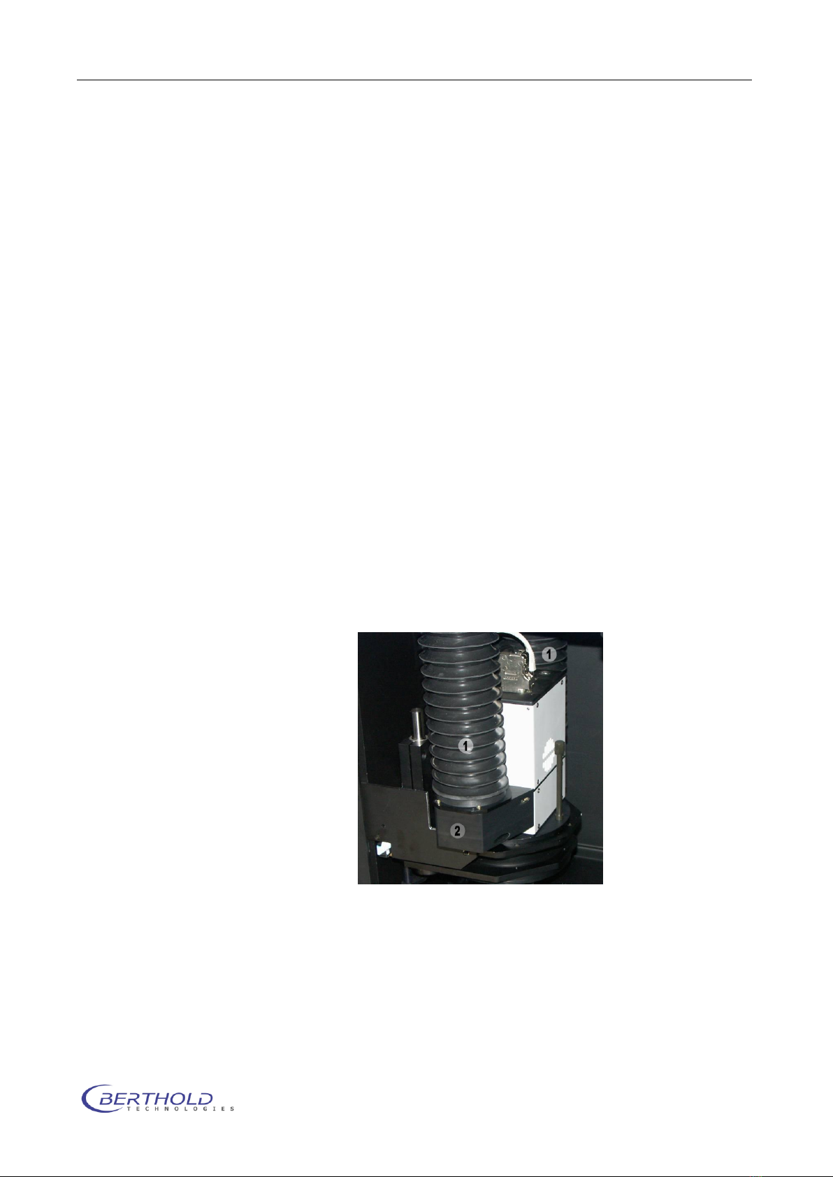
1.1 Camera installation (Ethernet version)
Place the camera on the camera holder showing the NightOWL
logo on the camera to the front. Fix the camera using the two fas-
tening screws as shown on the picture.
The two bellows (1) are fixed to the camera adapter (2) with spe-
cial magnets.
The Ethernet cable (RJ-45 connector) and the power supply con-
nector are plugged in at the upper plate of the camera.
1.2
Installation NightOWL LB 983
1-2
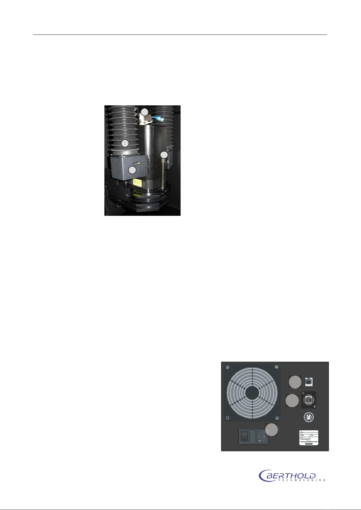
Camera installation (USB version)
The NC 100u uses the USB bus to transfer images and camera
control. To install the camera just place the camera on the cam-
era plate facing the “FRONT” label to the front.
Fix the camera with the 2 fastening screws (3). The power supply
(4) is connected through a 7 pin Tuchel connector. This connector
is on the camera face plate and connects to the power supply
connector on the camera plate.
The air adapter (1) is fixed to the camera by a megnet, as well as
the air bellow (2).
When uninstalling the camera remove the power adapter to avoid
damage during transport.
The USB plug is also located at the face plate of the camera. The
cables should be arranged as shown in the image above.
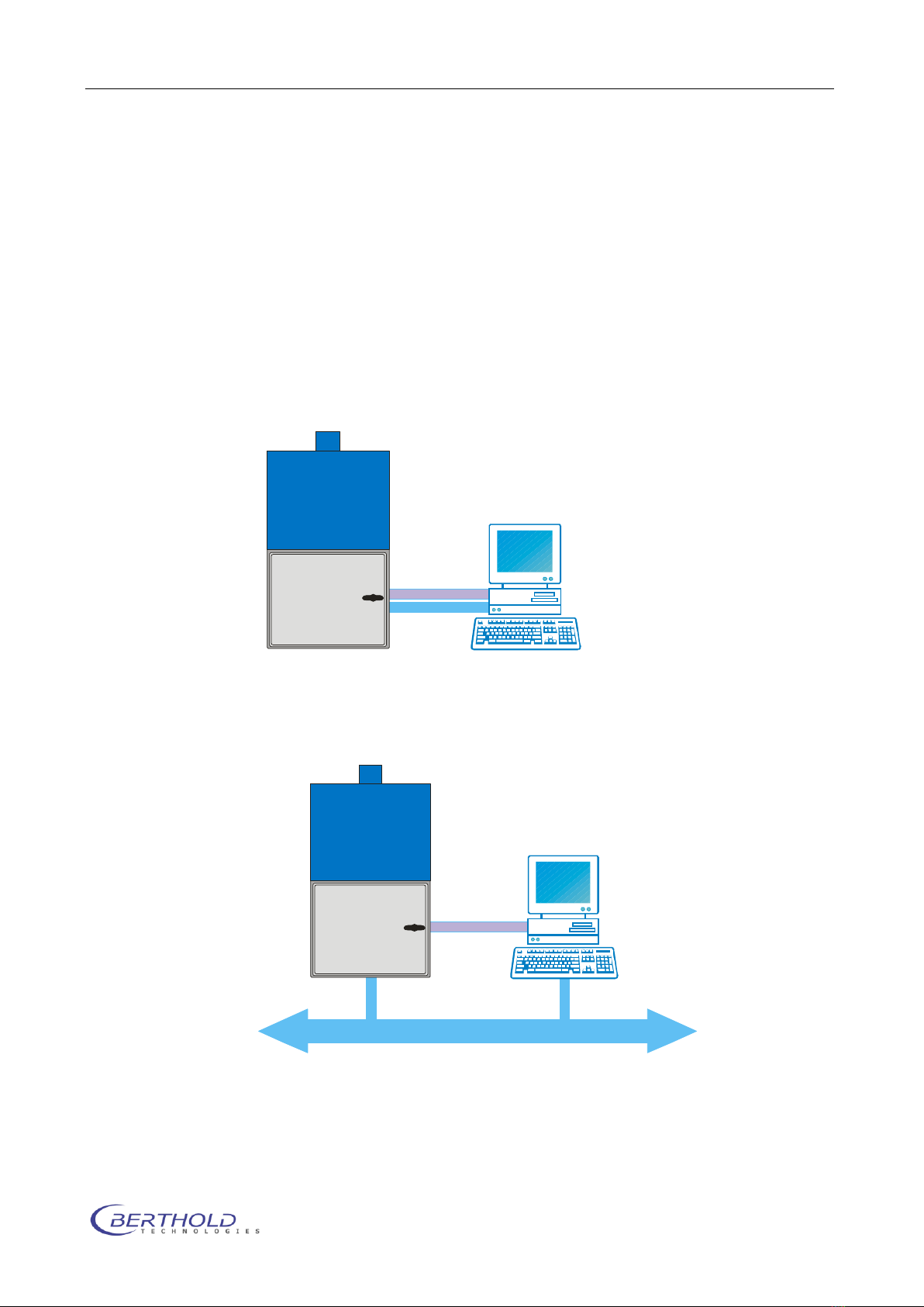
1.3 Connecting the instruments
Connect the instruments as follows:
PC -> NightOWL (rear panel)
Power -> Mains socket (1)
LAN port -> LAN socket (2)
(RJ-45 cable) and / or
USB port -> USB socket (3)
Check to make sure that the
system voltage indicated on the
instruments matches the line
voltage.
Connect all three instruments
(PC, monitor, NightOWL) via one
connector strip to the mains
1
2
3
4
CE
I
01
2
3
NightOWL LB 983 Installation
1-3
supply and turn the instruments on.
1.4 Connecting the PC (Ethernet)
The NightOWL camera transfers the image information using the
Ethernet bus. If the NightOWL is directly connected to the Ether-
net interface card of the PC, a so called “cross-over cable” is re-
quired (included with the shipment). This cable is plugged into
the network adapter on the PC, which is usually implemented on
the PC motherboard. If LAN access is required (internet, mail,
network printer) an additional network adapter (PCI, PCI Express
or USB) is required.
In case the NightOWL should be connected via LAN using the wall
socket or a network switch, a regular patch cable is needed.
Please keep the local IP address range in mind to avoid IP ad-
dress collisions. The direct connection between NightOWL and PC
is preferred.
To connect the NightOWL to the PC an Ethernet card with RJ-45
connectors is required. Most PCs have such a port already “on
board”. If not or if the network adapter is already in use, a regu-
lar PCI, PCI Express or USB network adapter (100 MBits) is re-
LAN
RS-232
Camera Control
Darkbox Control
LAN
RS-232
Camera Control
Darkbox Control

Installation NightOWL LB 983
1-4
quired. To install the network adapter, please refer to the corre-
sponding operation manual.
For a proper communication with the NightOWL, the IP address of
the PC must be set in the range of 192.168.1.xxx (except
192.168.1.117 -> default IP address of the NightOWL camera).To
setup the IP address of the PC, please refer to the manual of the
used operating system.
1.5 Connecting the PC (USB)
The USB version is easier to connect. Just use the supplied USB-
cable to connect the NightOWL to the PC.
After switching on the NightOWL the PC is recognizing new devic-
es and asks for drivers. The required drivers (camera and USB <-
> serial converter) are located on the installation CD in the
/drivers subdirectory.
1.6 USB Mode programming
When a NightOWL II was used with WinLight and the user wants
to upgrade to indiGO the mode of the USB communication must
be changed.
WinLight used the internal USB to serial converter in native mode.
That means the internal EEPROM of the converter chip was not
programmed specially. When plugging in the NightOWL it was de-
tected as USB to Serial converter. Using indiGO the communica-
tion mode was changed which requires the programming of the
EEPROM. This is done using the service software. Before running
the service software, make sure the following entries are in the
service.ini file:
[Settings]
ProgramEEprom=1
[EEprom2]
Manufacturer=BertholdTech
ManufacturerId=BT
Description=NightOwl
SerialNumber=BT040508
ProductId=0xB5F2
NightOWL LB 983 Installation
1-5
This mode requires the use of specifically modified Berthold Tech-
nologies drivers. Otherwise the device driver cannot be installed
successfully because of a different vendor ID of the USB device.
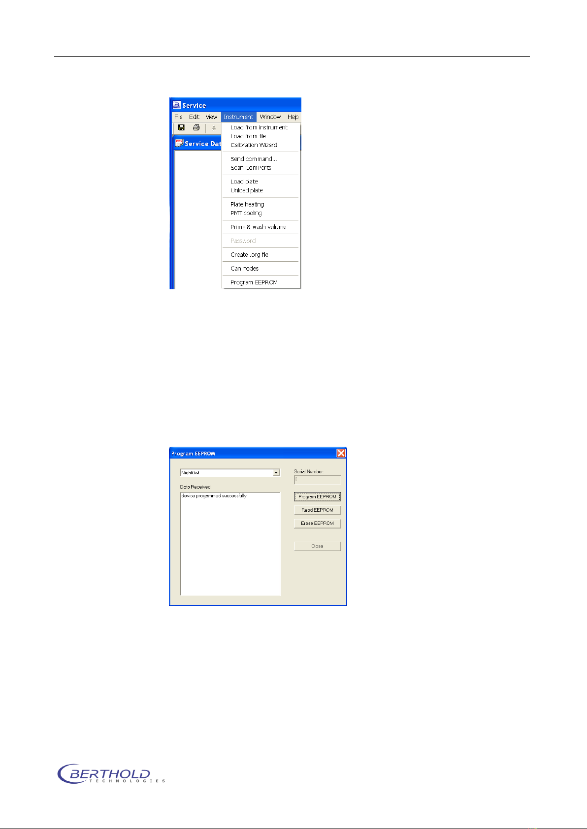
Run the service software and scan the com port to identify the
NightOWL (with not programmed EEPROM). If found select the
NightOWL entry in the found instruments list and select “Program
EEPROM” from the “Instrument” menu.
The programming dialog box will pop up. Click on “Read EEPROM”
to check if the communication is OK and the chip is not pro-
grammed.
When the readout was successful select the NightOWL from the
list of devices and click on “Program EEPROM”.
A successful programming is confirmed in the text area (device
programmed successfully). Now the NightOWL is programmed
and after power cycling the instrument (switch off, wait 5 se-
conds, switch on) the device will be identified as (Berthold Tech-
nologies NightOWL). In addition a NightOWL Serial Port is used to
be compatible with the WinLight software.
Installation NightOWL LB 983
1-6
1.7 Software installation (indiGO)
The indiGO software is included on the enclosed USB stick or CD.
Keep this media in a secure place. You will need it again for pro-
gram updates or new installation.
For the operation of the NightSHADE the indiGO software version
2.00 or higher is necessary.
We recommend using Windows XP SP3 or Windows 7 as operating
system. Older operating systems are not supported.
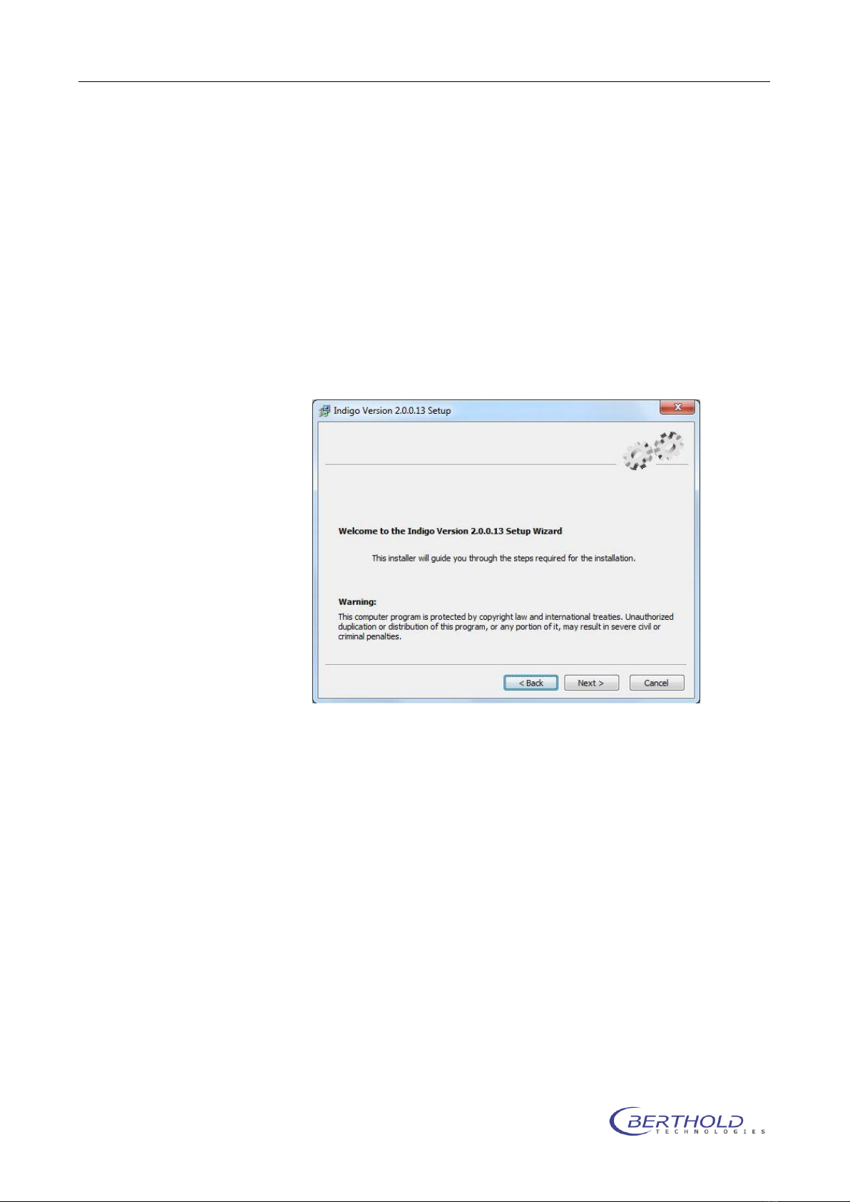
To start the installation program Click on the file SETUP.EXE on
the data carrier. After launching the installation program a wel-
come screen appears:
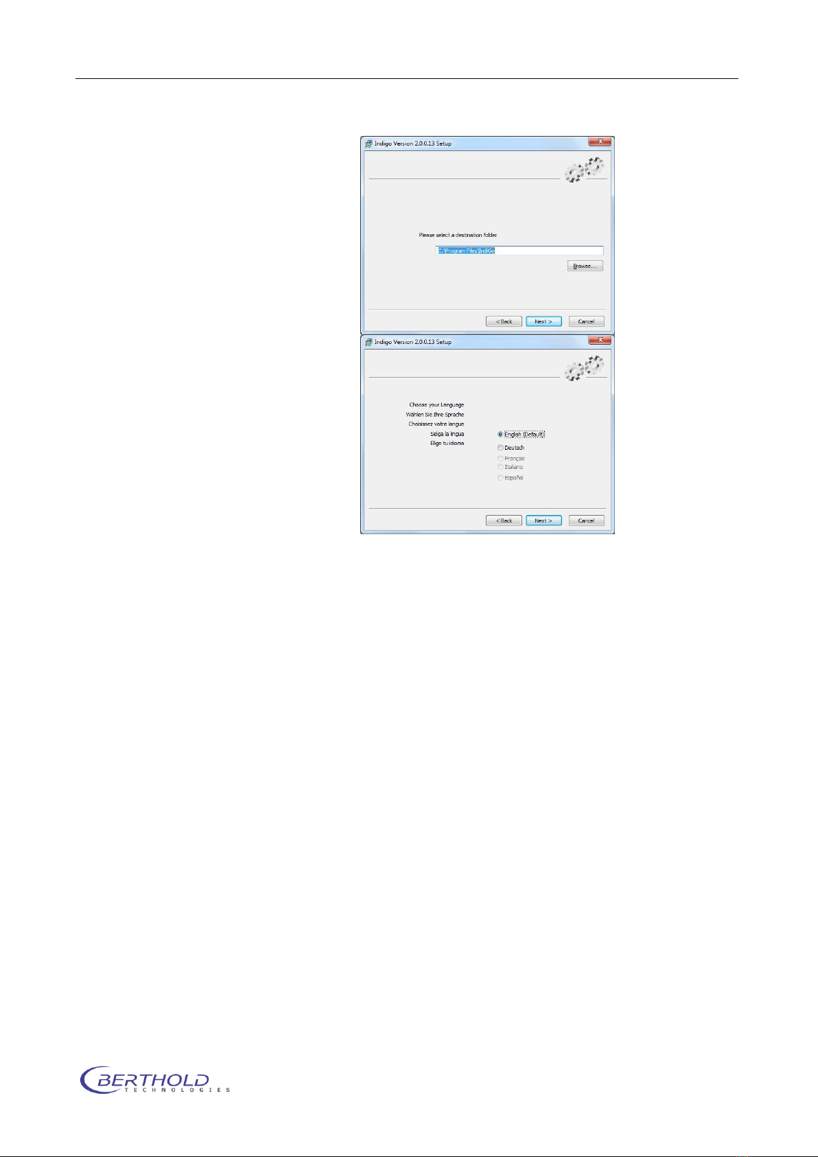
After the welcome screen the folder for the software installation
must be defined. If possible confirm the suggested folder.
To get to the next screen asking for the language of the indiGO
user interface (at them moment only English available) click on
[Next]
NightOWL LB 983 Installation
1-7
Depending on the hardware you use a default se-
lection of system filters might be available and can
be installed through the setup. If you want to in-
stall the default filters tick the box “Install de-
fault filters”.
In this case the default systems filter management
file will be copied to your computer. If you reinstall
the software the current active systems filter
management file will be overwritten.
Note: Since the setup will install virtual device
drivers for the NightShade hardware on your com-
puter the Windows-system might show a warning
that a signature of a Windows driver cannot be
verified. In this case allow the setup to install
these Windows drivers.
Important Note: To install these drivers and the software, you
need administrator privileges.
indigo is only tested on WinXP/Vista Windows7 32 bit systems.
Installation NightOWL LB 983
1-8
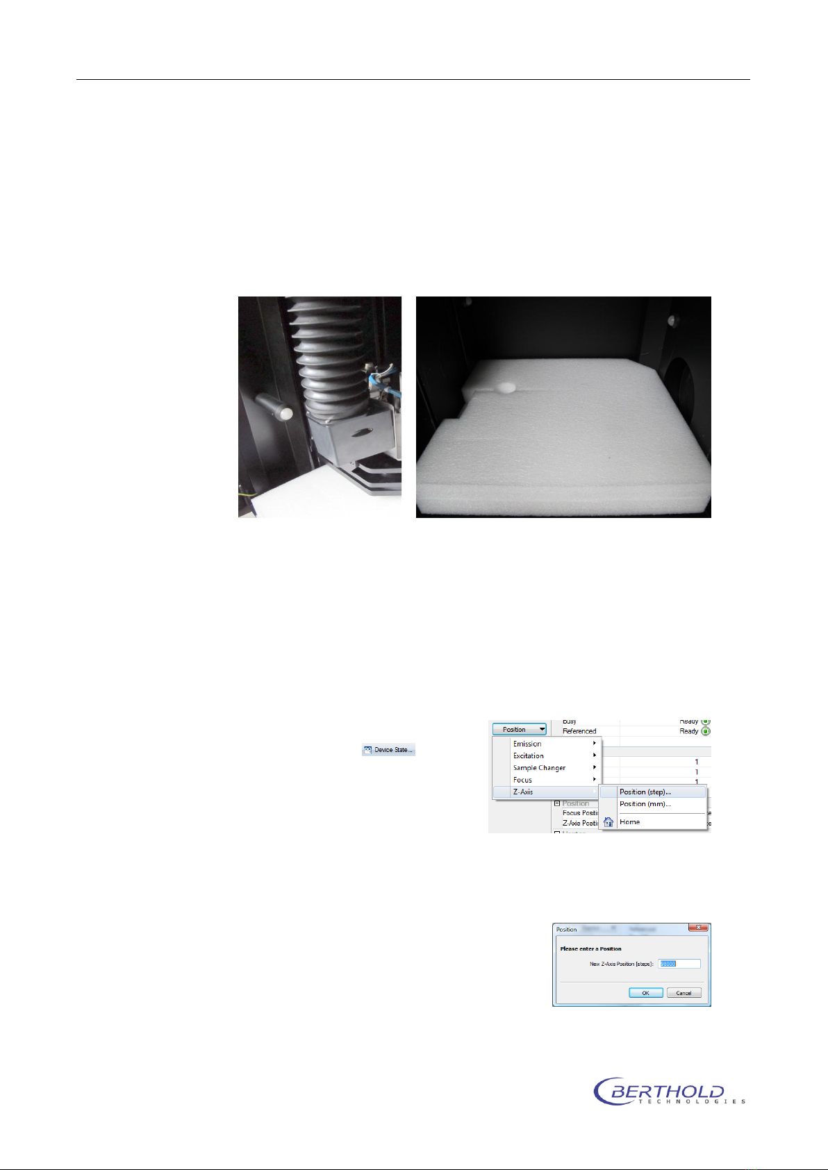
1.8 Shipping instructions
The NightOWL II must be shipped with the camera removed and
the foam piece laid on the bottom plate fixed with the camera lift
as shown on Figure 2:
Figure 2 Transport
holder
Proceed as follows:
Remove all filters from the filter wheel (empty wheel
mounted) and other accessories from the instrument and
place the foam piece on the base plate as shown in Figure
1
Move the camera (z-axis) into the low position (step
98000) using the ser-
vice software or indiGO.
Klick on , select
Position and choose Z-
Axis and Position from
the dropdown menu.
Enter 98000 steps at
the prompt and press
OK to move the camera to the shipping position.
The camera drive will block the foam piece and locks the
base plate.
Switch off the NightOWL II and do
not turn it on again since it will
move back to the home posi-
tion.
Remove the air adapters from the
camera, open the 2 thumb
Figure 1 foam piece
NightOWL LB 983 Installation
1-9
screws left and right of the camera, unplug the USB cable
and Power supply and carefully take out the camera.
Fix the transport holder for the air adapters as shown on
Figure 3. Use the grey spacers to avoid touching the lens.
Clip the air adapters to the
holder so that they are mag-
netically fixed.
Remove the power supply cable
from the instrument and place it
in the camera box.
Unscrew the noise killer at the
top rear side of the NightOWL
and place it in the camera box.
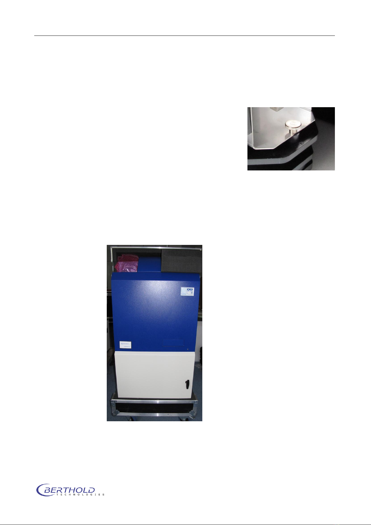
Close the front door and put the
NightOWL in the flight case. Close all Butterfly locks
Make sure that the blank transport flange without gas con-
nectors is mounted because the NightOWL will not fit into
the box with gas flange. Watch the position of the flange in
the flight case (recess). See Figure 4
Figure 4 NightOWL in flight case
Figure 3 fixing screw
with spacer

Calibration NightOWL LB 983
2-10
2. Calibration
2.1 Focus calibration
To run the focus calibration a focus target is required. This sheet
can be found at the end of this document. When printing out the
focus target make sure, the scale shown on the target is really
20cm as this will be used in the calibration.
Cut the left border off and place the focus target on the bottom
plate that the center of the star is in the center of the image.
Right click on the indigo instrument controller and login (setup)
as service user (login: “onki”; password “onki”). The backend of
indiGO will show up:
To run the focus calibration click on the item “Focus Table” in the
Calibration section. The current focus table will show up.
A new calibration will be performed by clicking on
Use the default settings as shown below. The calibration proce-
dure starts after clicking on
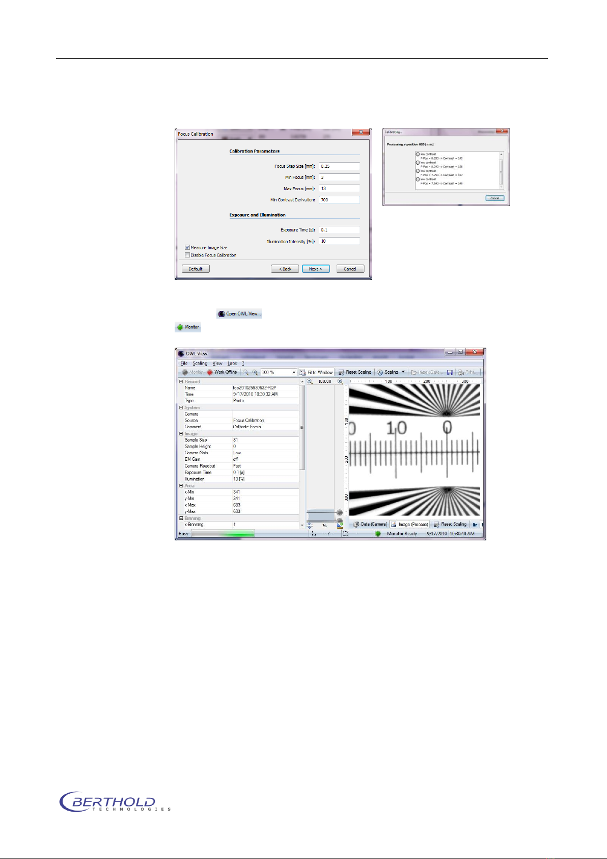
NightOWL LB 983 Calibration
2-11
To see the live calibration images, launch The OWLview Tool from
indiGO and enable the monitor mode by clicking on the
icon. Modify the scaling if required to see details. The whole
procedure will take 10 to 15 minutes.
In case of contrast problems modify the contrast deviation or the
illumination intensity. It is also possible to recalibrate a single po-
sition in the focus table. To do so right click the desired position
and select “recalibrate” from the list.
In order to “fine tune” the calibration it might be useful to rerun
the calibration a second time using a smaller focus step size to
get better precision in the large scale images.
Calibration NightOWL LB 983
2-12
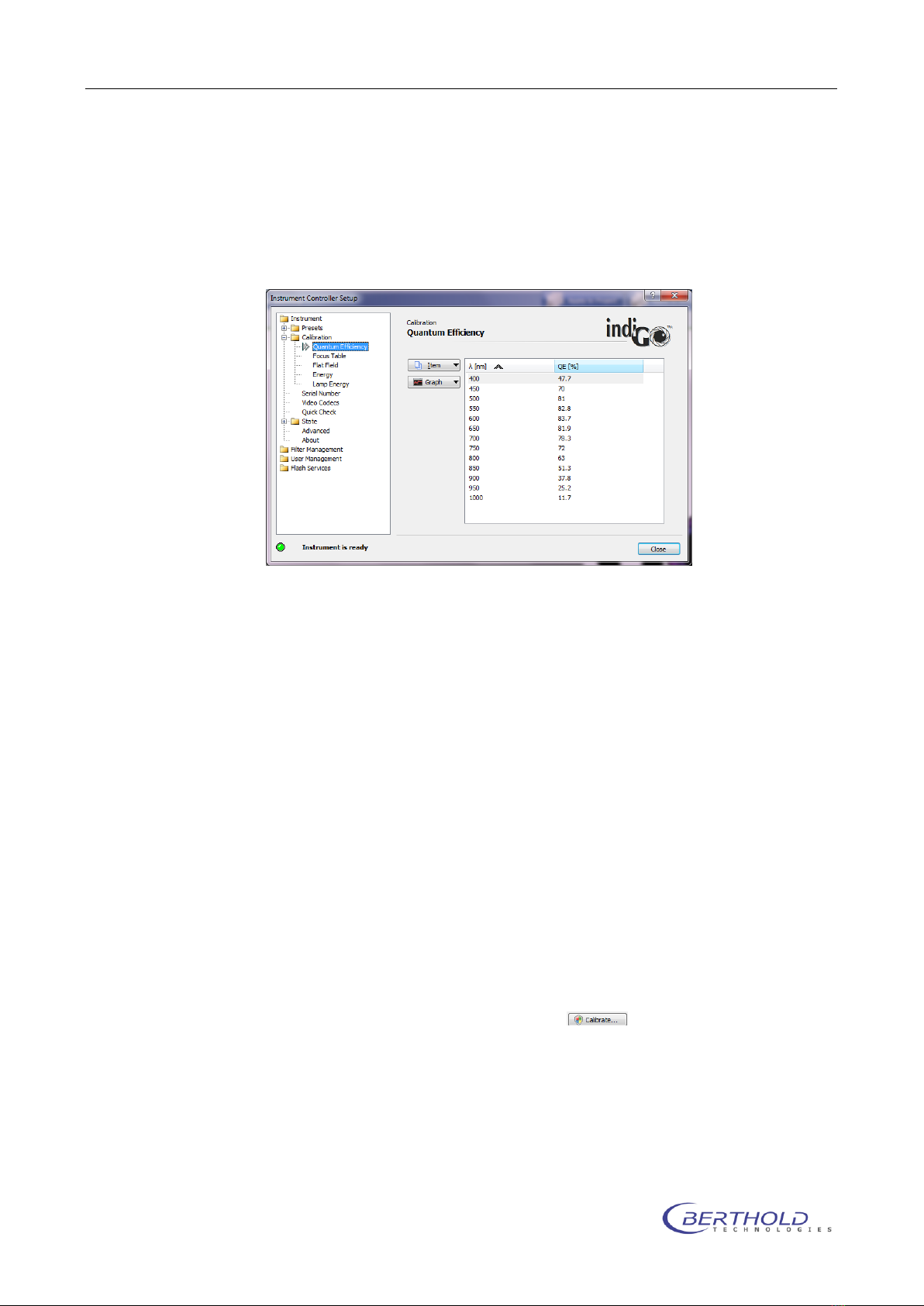
2.2 Quantum Efficiency
The quantum efficiency table describes the spectral efficiency of
the CCD chip. The table can be accessed by selecting “Quantum
Efficiency” from the Calibration section.
Depending on the camera used, this table might be different.
When using a NC 100 camera the quantum efficiency table should
look like as shown in the image. If no quantum efficiency entries
are shown, import the default values for the system (instrument
ID number –packet number) using the “Import configuration”
function in the “State - Advanced” section.
2.3 Flat field calibration
Since the lens is not uniform all over the image area a flatfield
correction is used to get rid of the so called “vignetting”. In order
to run the flat field calibration a clean white sheet of paper or
plastic is required (size min 270 x 270mm).
Place the white sheet on the bottom plate that the whole image
area is covered by the sheet.
To access the calibration, click on “Flat Field” in the calibration
section.
Start the calibration by clicking on . The standard parame-
ters should be used:
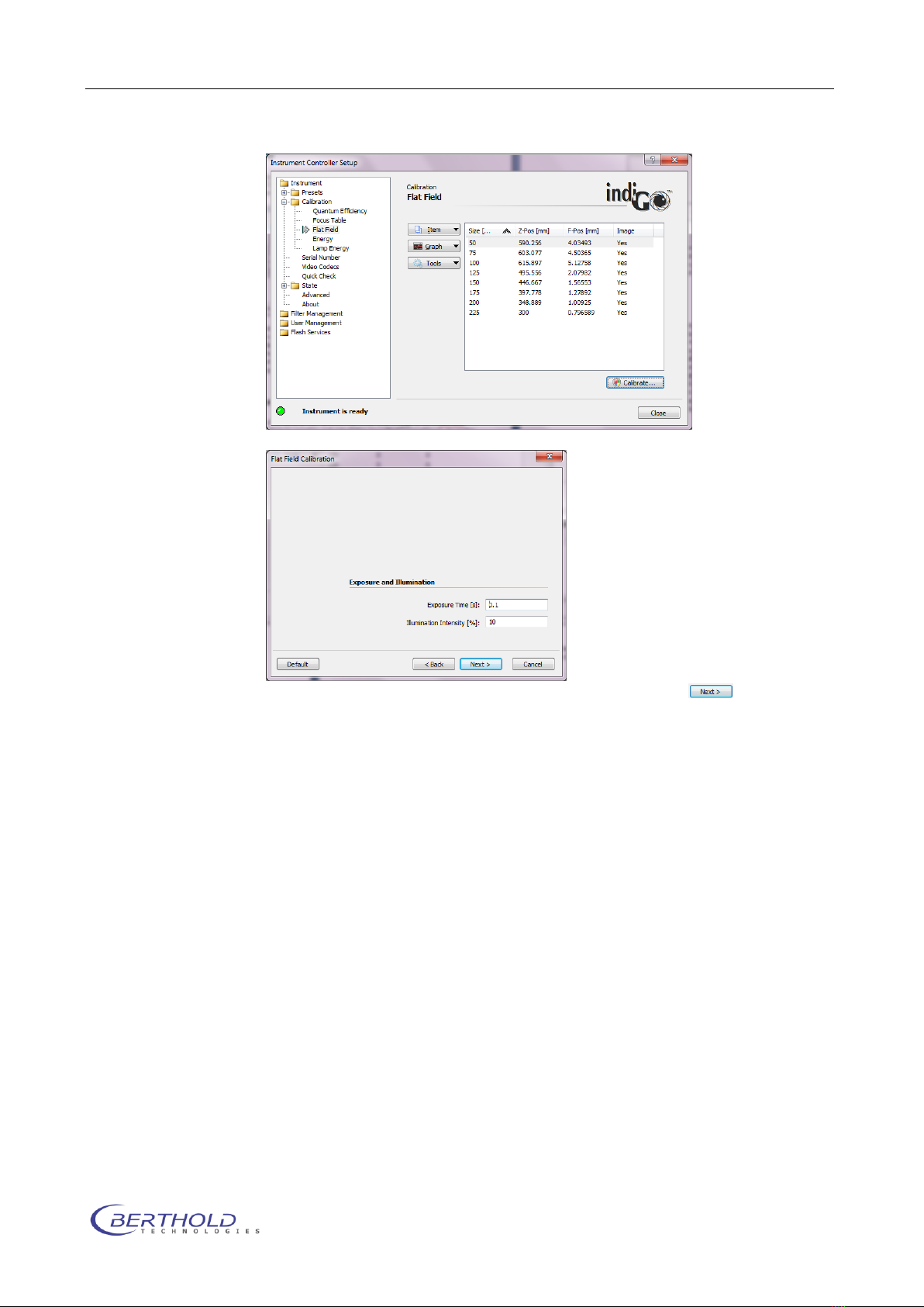
NightOWL LB 983 Calibration
2-13
The calibration procedure starts after clicking on
During the flat field calibration the system takes a photo of the
white sheet in the positions listed in the table and creates a flat
field correction curve.
2.4 Energy Calibration
The NightOWL camera is movable to allow large as well as small
image sizes without moving the sample. Without energy calibra-
tion the intensity measured with the NightOWL might be different
at high and low positions due to physical rules. To compensate
this, an energy calibration must be performed. A calibration light
Standard with known light intensity (ID 29687) is required to run
the energy calibration.
The light standard is supplied by the CAN-connectors located at
the rear right side inside the dark box. The standard must be
placed on the base plate so that the white overload well (E9) is
centered in the image.
Calibration NightOWL LB 983
2-14
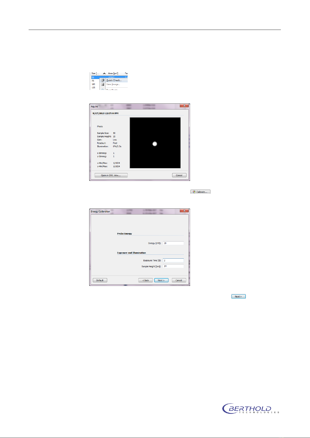
To check the positioning, select the item in the list with the small-
est sample size, right click and select “Quick Check”.
The sample should be positioned like this:
Start the calibration by clicking on . The standard parame-
ters should be used:
The calibration procedure starts after clicking on
The Berthold light standards are adjusted and certified to 20nW.
During the energy calibration the system takes images of the
light standard in the positions listed in the table and creates an
energy correction curve.
Check the calibtration images after the procedure using “View
Image” from the context menu if the exposure was not over-
range. Use a shorter exposure time if required (1s, 500ms). The
signal of the strongest image should be around 10000cts.
NightOWL LB 983 Calibration
2-15
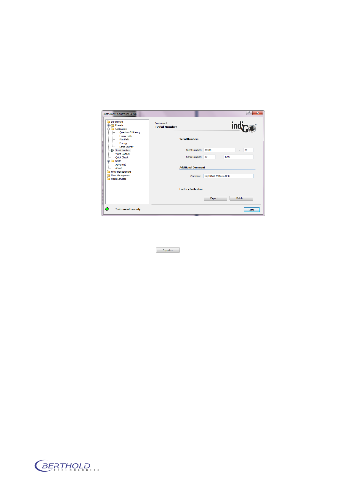
2.5 Calibration data
When all calibrations are done the calibration and configuration
data must be backed up to an external storage device (USB
Stick). This can be done in the Serial function of the Calibration
section.
Fill in the instrument ID number, packet number and serial num-
ber and click on to copy the calibration and configuration
data to a memory stick. Select the destination on the upcoming
dialog.
Store the memory stick in a safe location. Loosing this data re-
quires a new calibration in case of a new software installation.
The calibration data is stored in the /owlctrl/data subdirectory of
the program data directory. In Windows XP this folder can be
found in C:\Documents and Settings\All Users\Application Data.
In Vista and Windows 7 the program data is located in
C:\Program Data.
2.6 Other Data Files
In the /owlCtrl/data directory other configuration files are located
as well. The function is explained below.
owlCtrl.usr –This file contains all registered users. Do not
modify.
owlCtrl.flt –Filter configuration for excitation and emission.
owlCtrl.cdc –Video codecs list for video file creation.

Calibration NightOWL LB 983
2-16
owlCtrl.trc –Communication Protocol file. Might be useful
to send in case of any instrument/communication prob-
lems.
Indigo.net –User data and web update information. Do not
modify update information if not instructed since online up-
date might not work after modification.
owlCtrl.cnf –Contains the entire hardware configuration
and calibration oft he current system. This file is being re-
named after the import of the original file (e.g. 040508-30-
1010.cnf.
In folder /cdrv some default configuration files are located
in case of a new calibration or when no dedicated calibra-
tion file is available.
Table of contents
Other Berthold Laboratory Equipment manuals


Popular Laboratory Equipment manuals by other brands


Belden
Belden HIRSCHMANN RPI-P1-4PoE installation manual

Koehler
Koehler K1223 Series Operation and instruction manual

Globe Scientific
Globe Scientific GCM-12 quick start guide

Getinge
Getinge 86 SERIES Technical manual

CORNING
CORNING Everon 6000 user manual

Biocomp
Biocomp GRADIENT MASTER 108 operating manual


