Bertolini VIKING Quick guide

MOTORIZED CONTROL UNITS FOR
SPRAYERS
OPERATING, SET-UP, SERVICE
AND SAFETY INSTRUCTIONS
Reggio Emilia - Italy
Eng
VIKING

2
You have decided to choose “BERTOLINI” and you purchased a product manufactured using the
latest technology and the finest materials for the best in quality, duration and functionality.
We are grateful for your confidence in us.
Read this booklet and always keep it at hand; you will find it useful in resolving any doubts you may
have on the features and functionality of the product.
Thank you for choosing “Bertolini”
This instruction manual provides all the specific information necessary for familiarisation and use of
the remote control in your possession.
ATTENTION!
READ CAREFULLY THE INSTRUCTIONS CONTAINED IN THIS BOOKLET BEFORE
INSTALLING THE CONTROL AND REFER TO THEM WHENEVER DOUBTS ARISE ON USE OR
DURING MAINTENANCE OPERATIONS.
IDROMECCANICA BERTOLINI S.p.A. DECLINES EVERY CIVIL OR CRIMINAL
LIABILITY FOR DAMAGES AND ACCIDENTS, TO OBJECTS OR PERSONS,
THAT MAY ARISE ROM FAILURE TO OBSERVE THE SAFETY INSTRUCTIONS
PROVIDED IN THIS BOOKLET AND/OR SAFETY REGULATIONS IN FORCE IN
THE COUNTRY WHERE THE PRODUCT IS USED.
SAFETY INSTRUCTIONS
–Do not operate in the area of action of the system without being protected by suitable
protective goggles and clothing;
–Do not carry out operations without disconnecting the P.T.O. (stop the pump);
–Install adequate protection guards for all moving parts such as the shaft, pulleys, couplings,
etc;
–Do not remove the guards for the moving parts;
–Do not modify the control installation conditions and in particular do not modify the mounting
and hydraulic connections;
–Do not operate any taps not connected to a usage which may prevent accidental leakage of
the liquid being pumped;
–Make sure that there is safety valve of adequate capacity in the delivery circuit, in addition to
the pressure regulation valve;
–Make sure that the hoses are properly fixed before use by checking all the connections;
–Carry out, before use, the checks as specified in paragraph 6.
–Protect the control against icing in the winter period.
–Never leave the control at rest with the pumped liquid inside. Persistence of liquid in contact
with the internal parts of the control, when not necessary, can cause the control to deteriorate
more quickly.
–Stop the pump and release the pressure from the pressure circuit before carrying out all
maintenance or checks;
–Always DISCONNECT supply cables during maintenance on the machine or during long
periods of non-use;
–Children and animals must be kept far away from the pump;
–Do not use liquids with a temperature greater than 62°C or 145°F, or less than 5°C or 41°F;
–Do not introduce:
•Aqueous solutions with density and viscosity greater than those of water;
•Inflammable liquids or liquefied gases;
•Chemical solutions for which there is not guaranteed certainty of their compatibility with the
materials of which the control is made;
•Water for food purposes;
•Any kind or type of paints and varnishes;

3
•Solvents and thinners for any kind or type of paints and varnishes;
•Fuels or lubricants of any kind or type;
•Liquids containing granules or solid parts in suspension.
- Before any maintenance:
•Always make sure that the system pump is not operating and that the motorization of the
drive is completely disconnected.
•Make sure that the entire hydraulic circuit is not in pressure; therefore, close the pump
suction, relieve the pressure of the hydraulic circuit.
•Make sure that electrical supply connection is disconnected and that the metallic body of
any drive mechanisms is isolated.
•Always remove the battery connection cables while it is being recharged.
•Do not carry out electric welding with the power wires connected; make sure that they are
both (+ and –) disconnected, in order to avoid uncontrollable voltage peaks.
- Before using the system:
oMake sure that the connection hoses of the circuit are properly fastened by checking the
connections.
oCarry out adjustment of the distributor before work, only with clean water, making sure that
the various joints and connections are not leaking.
oEvery time the tractor is started and stopped the general valve must be brought to the OFF
position (“by-pass”), in order to avoid inconvenient problems;
oIn order to avoid danger to persons or the environment, it must be washed with clean water
at the end of every treatment.
Protect the environment from the liquids contained in the system.
Clean up residues and dispose of them regularly; no residue must enter the
canalization network or the ground.
ALL RIGHTS RESERVED. THIS MANUAL IS INTENDED
EXCLUSIVELY FOR USE BY THE CUSTOMER. ALL OTHER
USES ARE FORBIDDEN.
Index
1. General instructions and warnings.……………………………...………………………..….4
2. Product Description….……………………………………………………..………...………….6
3. Identification and description of components……...…………………………………...…..7
4. Installation………………………………………………………………………………………….9
5. Hydraulic connections…..……………….……………………………………………………....9
6. Control unit functioning and use…………..………….…..……….…………………………10
7. Control maintenance…………………………………………………………………………….12
8. Troubleshooting and cures………...….………………………………………......…………..13
9. Useful information…………..……….………………………………………………………......15
10. Components description-Wiring diagrams...………………………………………….…..16

4
1. General instructions and warnings
1.1 Assistance Service
It is possible to obtain assistance in all countries where the equipment is officially
distributed by Idromeccanica Bertolini (during and after the warranty period).
Any type of intervention required on the control unit must be carried out in accordance with
the information of this manual, or by following any agreements taken with Idromeccanica
Bertolini.
If this is not the case, the relevant warranty conditions may be annulled.
1.2 Warranty
Idromeccanica Bertolini S.p.A. undertakes, within a maximum of twelve (12) months
from the date of delivery of the product, to provide a replacement for any parts that have
manufacturing defects.
The warranty is valid only when the defect can be verified by the “Assistance Service”
and when it cannot be blamed on improper use or poor maintenance of the product.
Parts subject to normal wear and tear from use are excluded from the warranty
(parts made of rubber or plastic, gaskets), as well as labour costs and any other
request for damages or indemnity (for example, due to damages or interruption in
the use of the products).
“Idromeccanica Bertolini S.p.A.” IS NOT responsible in terms of warranty and
compensation, for damage caused in the case of:
•Transport damage (breakages, scratches, marks or similar)
•Use of the product different to those indicated in the manual
•Use that does not comply with the specific regulations in force
•Improper installation or defects originating from insufficiency or inadequacy of the
electrical system, or alterations deriving from environmental, climate or other types of
conditions.
•Use of unsuitable liquids
•Negligence, neglect, tampering, unskilled use or repairs carried out by unauthorised
personnel.
Poor maintenance
•Modifications or interventions not authorized expressly by “IDROMECCANICA
BERTOLINI S.p.A.”
•Use of spare parts and accessories that are not original and/or specific for the product
•Use of hoses and connections that are not prescribed by this manual or not suitable for
the product and its use.
Furthermore, the following are not covered by the warranty:
•Installation and adjustment
•System consultancy or makeshift inspections
•Various maintenance operations (such as cleaning of filters, nozzles etc.)
•Normal depreciation due to use

5
And in any case:
The restoration of the equipment will be carried out within time limits that are compatible
with the organizational requirements of the Assistance Centre.
•The products to be repaired must be washed in advance and cleaned of residues from
chemical products use
•Repairs carried out under warranty do not give rise to extensions or renewal of the
warranty
•NOBODY is authorized to modify the terms and conditions of warranty or to issue any
other verbal or written warranties
•The parts replaced under warranty remain the property of “IDROMECCANICA
BERTOLINI S.p.A”.
Where the product has been tampered with, “Idromeccanica Bertolini S.p.A.”, declines
all obligations under the warranty.
For all verifications, the products can be returned only on written authorisation from
Idromeccanica Bertolini S.p.A. and only freight prepaid.

6
2. Product description
The spraying control units of Idromeccanica Bertolini are only applicable to the systems
driven by diaphragm or piston volumetric hydraulic pumps. They are suitable for sprayers
in agricultural field, atomizers, private and public hydraulic systems, fountains, etc.
The spraying control units are composed of motorized or/and manual electrical section
valves conceived and studied to overcome the traditional product problems ensuring
always high performances.
-The basic characteristics of those valves are:
-Non-deformable at high and low temperatures;
-Complete watertight seals;
-Free assembly position;
-Thermal protection against accidental circumstances;
-overtime duration;
-controllable with a simple bipolar switch;
-Single or parallel functioning;
-System versatility;
-No current absorption when adjusted.
The materials used are: high resistance plastic materials (polypropylene +Fiberglass),
stainless steel, and Viton gaskets and this makes them compatible with very aggressive
chemical solutions.
A motorized electric unit, modularly built in different configurations, each of them with
specific characteristics, according to the client’s need, is composed of section valves (until
7 max. sections), volumetric valve, adjustable pressure relief valve and main on-off valve.
The max working pressures, according to the technical characteristics of the components,
are: 20 bar or 40 bar.
The motorized valves are controlled by sprayer controls or by computer B.Matic 500 (all of
them supplied separately) and each of them is for DIN 43650-A/ISO4400 connections.
The voltage must be always:
12 VDC 2
0.5 A valve VV
12 VDC 2
1.5 A valves: VG, RS, RD
This is the normal voltage for a battery in the most common agricultural equipment.
Out of this field, you may incur functioning problems or damages to the internal electronic
circuit.

7
INSTALLATION DIAGRAM
vsvgvv
(RD)
RSRS
(RD)
Pompa
Cisterna
Uscite Barre
IN
OUT1
OUT2
VALVOLA DI
SICUREZZA
WARNING! For a correct
functioning, do not connect the
return hoses to the bottom of the
tank with the aim to use them as
hydraulic agitators, but connect
them exclusively to the top part
of the tank.
Use only components (hoses,
clamp, fittings, etc.), which
minimum characteristics are
equal to the max pressure of the
pump or the control; make sure
not to create throttling during the
course.
Components Index:
•VS: manual adjustable pressure relief valve;
•VG: main ON-OFF valve;
•VV: volumetric adjustable pressure valve
•RS: section valve RS
•RD: section valve RD
•A1: water inlet (connect the hose coming from the pump)
•A2: By-pass, section valve, general valve and volumetric valve discharges.
(connect the return hose to the tank)
•A3 (bypass): RD section valves discharge (connect the return hose to the tank)
•A4:Delivery system (connect to the boom)
•B: DIN plug 43650-A (2 poles + ground)
3. Identification and description of the components

8
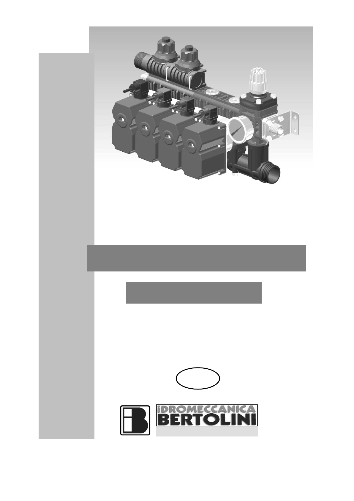
•C: Position indicator, indicates, according to its colour, the ball position. The colours are
RED and GREEN.
•D: adjusting pressure relief valve knob. Unscrewing manually this part the maximum
pressure is increasing.
•E: compensating discharge adjustment knob. Unscrewing manually this component the
water coming back to the tank decreases, therefore pressure increases.
•M: Pressure gauge
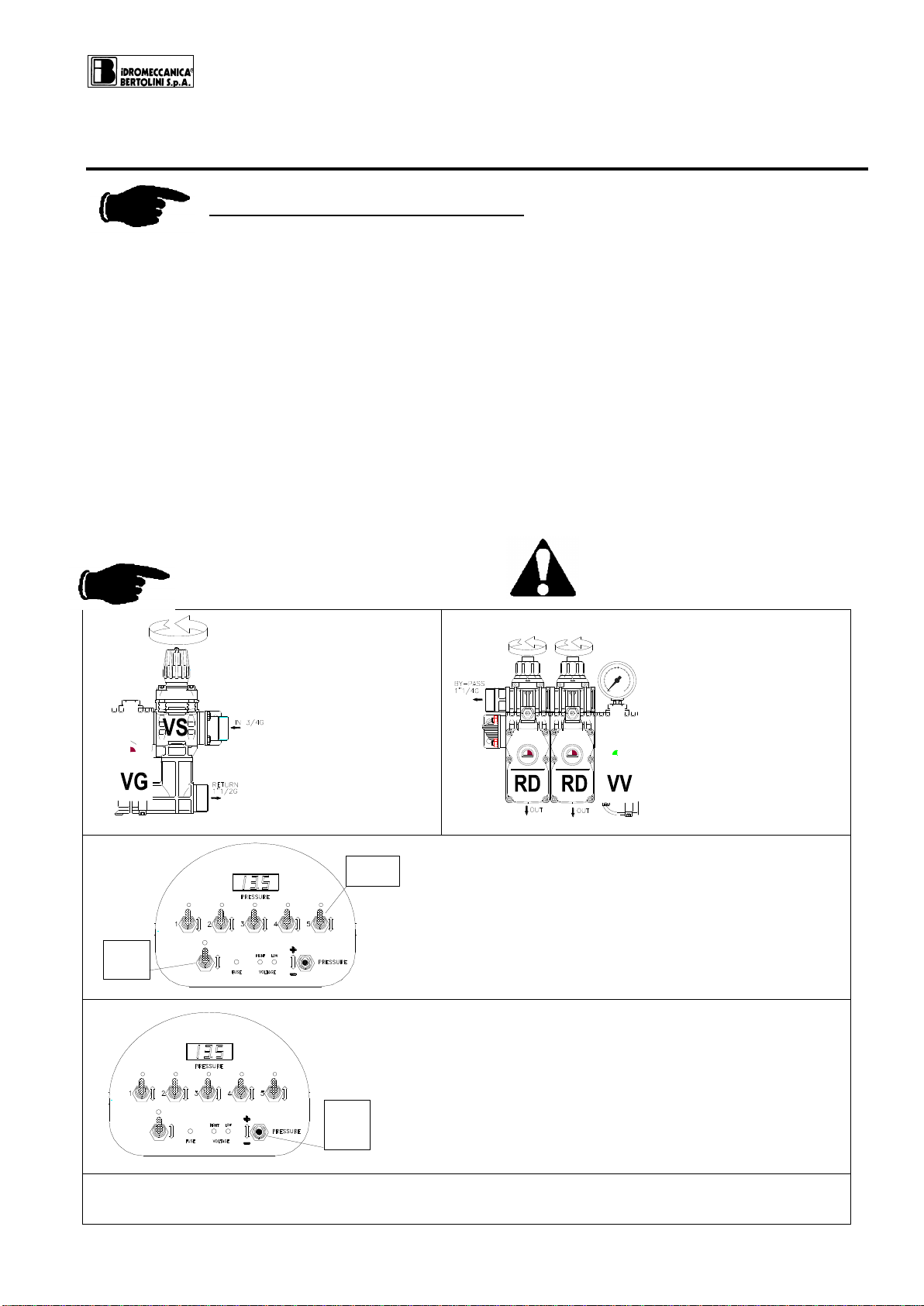
All the control units made by IDROMECCANICA BERTOLINI S.p.A. are always fitted
with the VS adjustable pressure relief valve.
The adjustment of this valve is made by the operator, who must adjust the pressure
to a value that is higher than the maximum working pressure, but lower than the
maximum security pressure attainable by the hydraulic system.
ANYWAY THE MACHINE MUST BE PROVIDED WITH A SEPARATE SAFETY
VALVE, SET AT THE WORKING PRESSURE THAT IS NOT HIGHER THAT
10% OF THE MAX.PRESSURE OF THE HYDRAULIC SYSTEM.
Description of the functions
1. VS Pressure relief valve: It is adjusted manually by its knob (screwing it, pressure
increases, unscrewing it, pressure decreases).
It discharges into the tank the excess liquid when the adjustment pressure is obtained.
2. VG: Main ON-OFF ball valve: it opens or closes the discharge to the tank. The valve
position is showed by the indicator:
•“GREEN” position: discharge to the tank.
•“RED” position: working condition.
It is, for its function, always fitted after the VS valve, in order to use only one
discharge hose.
3. VV: volumetric adjustable pressure valve: It adjusts manually the spraying pressure,
if connected to a sprayer control or automatically if connected to a computer B Matic
500. In this case it provides to increase or to decrease pressure at variable driving
speed of the tractor, keeping the same amount of liquid per surface unit (ex.
Litre/hectare).
The liquid in excess is deviated to discharge.
The valve position is showed by the indicator:
•“GREEN” position: discharge to the tank
•“RED” position: working condition
The rotation of pin is not instantaneous but gradual; it can be 9 seconds (suggested for use
with computer) or 21 seconds (suggested for use with sprayer control).
4. RS section valve: it opens or closes the corresponding boom section; it discharges the
liquid in the tank by the VS valve or VG valve, if present.
The valve position is showed by the indicator:
•GREEN” position : closed boom (discharge in the tank)
•“RED” position: working condition (liquid to the boom)
5. RD section valve: The RD valve is a “deviating valve” that adjusts in by-pass the liquid
amount that you have established with reference to counter clockwise knob adjustment.
This implies a pressure variation if all of the section valves are not adjusted at the same
value (ATTENTION THE ADJUSTMENT IS VERY IMPORTANT).
If you want to increase the pressure to the boom the knob will be turned counter clock-

9
wise. If you want to decrease pressure you must turn it clockwise.
The section valve must be adjusted all the times that a different nozzle is used, so
the constant liquid distribution is ensured.
6. M Pressure gauge: it shows the working pressure when the VG main valve is closed
(red position showed by the indicator).
4. Installation
The control unit model must be chosen by the manufacturer, according to the
chemical product nature and the system features. Failure to follow this warning
can result in injury and/or property damage.
The sprayer manufacturer should take care of the proper selection and correct size of the
hoses and connections that must correspond to the dimensions of the recommended
fittings.
Be sure that the control unit is attached to a strong base plate and anchor it with bolts
sufficiently strong to hold it in place. We recommend to protect your control unit from the
bad weather and from the spraying effects during the treatment.
The hoses dimension should not be smaller than the control units’ pipe fittings diameter.
5. Hydraulic connections
•Connect the delivery hose from the pump to the INLET fitting (IN) ;
•Connect the return hoses to the tank for the unused liquid to the by-pass fittings (by-
pass);
•Connect the hoses to the boom to the delivery pipe fittings : they must be equivalent
(same number) to the boom sections or hydro-agitators , if any;
Failure to follow this warning can result in personal injury or environmental
damage and/or malfunctions of the control unit and consequently will void the
product warranty.

10
6. Control unit functioning and use
General checks before the use
•At every use, clean the filter on the control (if present) and every other filter present on
the system; this simple operation will help you to keep the system efficient and to carry
out the treatments in the best way possible.
•Close all pressure hoses connected to the nozzles or boom; an open nozzle can
cause serious damage to persons, animals or things in the vicinity.
•Check the state of the hoses each time the system is used; also make sure that all
connections are tight and secure.
•Check the state of connection cables and electrical connections each time the system
is used; also make sure that the batteries are charged optimally (for motorized versions
only).
•Inspect the control and its components periodically. Routine maintenance of the
system protects your investment.
•Make sure that when the pump is being started up, the general valve is kept in by-pass
position as indicated on the label.
ADJUSTMENT (see Pict.1 page 9)
1
Unscrew
completely the
VS valve
adjustment knob
(minimum
pressure)
2
Unscrew
completely the RD
valve adjustment
knob (if it is
installed)
OFF
ON
COMANDO
VALVOLA
GENERALE
VG
INTERRUTTORI
COMANDO
BARRE
OFF
ON
OFF
ON ON
OFF
ON
OFF OFF
ON
3
Close all the RS or RD section valves operating
the control panel switches (“OFF” position: led
turned off)
Close the VG main on/off valve operating the
control panel switches
( “OFF” position: led turned off)
ON
OFF
ON
OFF
ON
OFF OFF
ON ON
OFF
ON
OFF
COMANDO
VALVOLA
REGOLAZ
PRESSIONE
VV
4
Operate the volumetric valve at the max.
pressure, by turning the switch upwards.
5
Start the pump and operate it to the correct R.P.M.

11
6
ON
COMANDO
VALVOLA
GENERALE
VG
OFF
ON ON
OFF
OFF
ON
OFF
ON
OFF
ON
OFF
Open the VG main valve operating the
control panel switch ( “ON” position:
led on)
7
Adjust the pressure relief valve VS, turning the
knob in a clockwise direction, until pressure
reaches the established value, make sure not to
exceed the max pressure allowed. In any condition
this safety value will never be overcome, unless
the discharge hose is obstructed.
8
Open the booms operating the corresponding switches (“ON” position led on).
9
Operate the machine at the established working pressure, by turning the volumetric
valve switch.
(10) RD valves adjustment (IF THEY ARE FITTED)
The RD valve adjustment must be carried out operating one boom each time.
a) Close just one boom operating the corresponding switch. You will see in the
pressure gauge a pressure change compared to the previous value.
b) Adjust the pressure to the requested value moving the RD adjustable knob.
c) Open and close the boom checking that pressure is constant.
d) Repeat the operations of the previous steps for all the other booms.
The operations from step 6 to step 9 (10) must be repeated if the nozzles dimensions
are changed

12
7. Control valve maintenance
ATTENTION!
Before starting any maintenance operation or inspection of the control unit,
wash it first with pure water, then completely empty out all liquid contained.
Pay particular attention to the parking of the machine on which the control unit is
mounted, in order to avoid danger to you or those around you.
Never carry out maintenance with children nearby!
Protect hands, eyes and body with suitable clothing; the control unit could have
been used with chemicals that damage your health.
The control unit is made from inedible parts. Do not bite, suck, chew or ingest any
part of the control unit for any reason.
Protect the environment from the liquids contained in the control unit.
Clean up residues and dispose of them regularly; no residue must enter the
canalization network or the ground.
Attention! Bertolini electrical valves are designed in order not to be opened;
therefore, when necessary, always replace the complete valve. Opening or
tampering with valves by non-authorized personnel invalidates all terms of
warranty.
USING “ORIGINAL BERTOLINI SPARE PARTS”INCREASES THE LIFETIME OF
YOUR CONTROL UNIT, BY ALLOWING IT TO OPERATE IN THE BEST POSSIBLE
CONDITIONS.
In the case where the control unit has to be dismantled, it is advised to change the sealing
O-rings, since they could get damaged during this phase, causing leakage of liquid in the
various valves.
Routine maintenance of the distributor protects your investment.
During the functioning it is possible that with closed valves (red colour indicator) the liquid
is coming out from the boom, in this case it is possible that the ball and/or its gaskets are
worn.
•Ball and/or gaskets replacement:
Remove the flange of the ball, take out the ball and the gaskets and check wear.
Replace the necessary parts and reassemble.
The corresponding kit that must be ordered to IDROMECCANICA BERTOLINI, are the
following:
•Part N° 24.5334.97.3 →VG (40 bar), VV 39 (9-21 sec.) valves;
•Part.N° 24.5335.97.3 →VG (20 bar) valve;
•Part.N° 24.5336.97.3 →RS (40 bar), VV 27 (9-21 sec.) valves;
•Part.N° 24.5337.97.3 →RD (20 bar), RS (20 bar) valves;
•Part.N° 24.5338.97.3 →RD (40 bar) valve
•Wash carefully with water the internal parts of the distributor after each treatment.
•Disconnect voltage during any maintenance.

13
8. Troubleshooting and cures
Before contacting the “Bertolini Assistance Service”, check the following chart:
TROUBLES
CAUSES
CURES
The regulator does not reach the
desired pressure
Not enough liquid arrives at the
control unit
•Check that the pump rotation
speed is correct
•Check that the pump flow rate is
correct
•Check that there are no
deviations open before the
distributor
•Check that the nozzles are in
good condition and of the correct
dimension
The discharge of the self-cleaning
filter (if installed) is fully open
Close the discharge of the self-
cleaning filter
The safety valve is fully unscrewed
•Consult the use and
maintenance booklet
•Check the orientation of the
valves balls
•Consult the use and
maintenance booklet
The volumetric valve (if installed)
and/or the main on/off are fully open
The compensating discharges are
not properly calibrated
The safety valve seat and/or the
ceramic poppet are worn
Change the valve seat and/or the
ceramic poppet
The ball and/or valve seals of the
volumetric valve and /or of the main
on/off valve are worn
Change the worn ball and seals
Liquid comes out from the boom
and the led of the motor geared is
red
The ball and the section valve
seals are worn
Replace the ball and the seals
Wrong orientation of the ball
Check the ball position
The ball doesn’t rotate completely
to 90°
Replace the section valve
Liquid is escaping from the
control pin of the ball
of the valve
The O- Rings of the control pin
are worn
Replace O-Rings
Liquid is escaping from the knob of
the safety valve
Diaphragm and/or O-Rings of the
piston are worn
Replace the diaphragm and the O-
Ring of the piston
Liquid is leaking from the RD
discharge knobs or between valve
bodies and the discharge
O-Rings on the knobs are worn
Replace
Liquid is escaping between the
bodies of the section valves or
between the RD discharge hoses
O-Rings are worn
Replace
Liquid is escaping between the
valve body and the manifold or
between the valve and the ball
flange
O-rings are worn
Replace
The geared motors work but no
water comes out from the nozzles
Clogged nozzles
Clean the nozzles
Wrong position of the ball
Check the position of the ball
The control unit remains still in
pressure
The main VG valve doesn’t work
Check that the connections respect
the electrical diagram
The pump pressure hose is bursting
Hose with unsuitable dimensions or
characteristics
Use hoses with suitable dimensions or
characteristics
Pressure hose connected instead of
the discharge hose
Check the hose connections using the
correct diagram
Discharge hose obstructed
Check the condition of the hose
With the section valves open and
Nozzles clogged
Clean the nozzles

14
the main on/off valve in the ON
position, no water comes out of the
nozzles
The ball of the main on/off valve
is positioned incorrectly
Check the position of the ball
It is not possible to get an accurate
pressure adjustment
Not enough liquid arriving at the
control unit
Check that the pump RPM are correct
Check that there are no deviations
open before the control unit
When closing one or more sections
the pressure is subject to wide
variations
The RD outlets are badly calibrated
Consult the use and maintenance
booklet
The delivery hose, the pressure
gauge and/or the pressure value
read by the sensor pulsate
The inflation pressure of the
accumulator on the pump is not
correct
Adjust the pressure to a value suitable
to the working pressure (see the
instruction booklet of the pump)
Hydraulic agitator connected to the
main discharge
Connect the agitator to a free section
valve
Difference between the pressure
read on the gauge and that read by
the pressure sensor
Pressure gauge or sensor damaged
Check and change the damaged
device
The two instruments are situated in
areas with different working
pressures
Check the system and , if necessary,
move one of the two devices
None of the geared motors are
working.
Inversion of the power supply
polarity of the panel
Check the connections of the control
panel power supply
Control panel and/or wiring not
working
Check if all the connections of the
cables are correct
Change the control panel or the wiring
Inadequate supply voltage
Check the charge level of the battery
and/or that the alternator is functioning
properly.
No 12VDC power supply.
Check the state of the wiring and if
necessary restore any interrupted
connections.
Check the protection fuse that may be
present in the power supply circuit.
One or more valves do not work or
work intermittently.
Not enough power to drive all the
geared motors.
Check the charge level of the battery
and/or that the alternator is functioning
properly.
Connectors not connected.
Check the wiring.
Restore any disconnected
connections.
Connectors connected badly
Electric motor damaged
Change the geared motor
Damaged/defective electronic circuit
Change the circuit.
Wrong electrical connections
Check that the connections reflect the
electrical diagram
The geared motor performs a
movement and then stops working
(the polyfuse intervenes).
Wrong electrical connections
Damaged/defective electronic circuit
Excessive load on the ball
Change the circuit.
Reduce the load from the flange to the
ball, slightly loosening the screws of
the flange
Presence of deposits on the ball or
the rod.
Remove the deposits or change the
components
Moving mechanical parts worn /
damaged
Change the geared motor or the
components that are creating the
problem
The motor is working but the
control pin is not moving
Problem on the mechanical part of
the geared motor
Replace the geared motor
When operating the volumetric valve
pressure increases instead of
decreasing and vice versa
Wrong electrical connections
Check that the connections follow the
electrical diagram

15
As a result of the normal wear of the nozzles it may become necessary to check their flow
rate and therefore their efficiency periodically. To do this, proceed as follows:
a. Take the system to working conditions.
b. Measure the flow rate (Q –litres supplied in one minute) of a nozzle using a graduated
container (Pict.17). Compare the values measured with the corresponding
measurements given in the charts provided by the manufacturer of the nozzles used.
If you wish to check the litres supplied per hectare (l/ha), insert the data in the following
formula:
Where:
Lh = applied volume (l/ha)
Q= nozzle capacity (l/min)
I= interspace between the nozzles (m)
V= advancing velocity (km/h)
If instead you need to know the required flow rate, insert the data in the following formula:
9. Useful information
Fig. 17
VI Q
Lh **600
=
600 ** VLbarraLh
Q=

16
10. Components description Wiring diagrams
VS Adjustable pressure relief valve (20 –25 –40 Bar)
It is a manual pressure relief valve.
It is available in 2 versions:
•up to 20 bar;
•up to 40 bar
Technical data:
Model
Part. Number
Max. pressure
Flow
OUT
Bar
PSI
Lit/min.
USGPM
Gas
VS 20
24.5024.97.3
20
300
300
80
1”1/4
VS 25
24.5172.97.3
25
362
220
58
1”1/4
VS 40
24.5025.97.3
40
600
220
58
1”1/4
Constructive features:
1. Valve seat made up of AISI 303
stainless steel;
2. Ceramic poppet;
3. Body made of polyamide
strengthened with fibreglass;
4. NBR diaphragm.
Fig. 2

17
VG Main ON-OFF ball valve (20 –40 Bar)
The main on/off valve is a motor powered valve with 2 positions (ON-OFF) and by-pass
function.
Constructive features:
1. Polypropylene ball (20 bar) or stainless steel AISI 316 ball (40 bar);
2. PTFE seals;
3. Body made of polyamide strengthened with fibreglass;
4. DIN 43650-A / ISO 4400 connection;
5. IP 65 protection;
6. Viton gaskets.
Technical data:
Model
Part number
Ball
Max. pressure
Flow
OUT
Bar
PSI
Lit/min.
US GPM
Gas
VG 20
24.5125.97.3
39 P
20
300
450
120
1”1/4
VG 40
24.5137.97.3
39 I
40
600
120
32
1”1/4
P= Polypropylene I= Stainless steel
Electrical Diagram
Fig. 3
Fig. 4

18
RS Section boom valve (20-40 Bar)
The section boom valve is a motor powered valve with 2 positions (ON-OFF).
Constructive features:
1. Polypropylene ball (20 bar) or AISI 316 stainless steel ball (40 bar);
2. PTFE seals;
3. body made of polyamide strengthened with fibreglass;
4. DIN 43650-A / ISO 4400 connection;
5. IP 65 protection;
6. Viton gaskets.
Technical data:
Model
Part number
Ball
Max. pressure
Flow
OUT
Bar
PSI
Lit/min.
US GPM
Gas
RS 20
24.5133.97.3
39 P
20
300
450
120
1”1/4
24.5206.97.3
27.5 P
200
52
1”1/4
24.5207.97.3
27.5 P
120
32
B
RS 40
24.5144.97.3
27.5 i
40
600
120
32
1/2
P= Polypropylene I= Stainless steel B= Hose tail with bayonet
Electrical Diagram
Fig. 7
Fig. 8

19
RD Section boom valve (20-40 Bar)
It is a motor powered valve with 2 positions (ON-OFF).
Technical data:
Model
Part Number
Ball
Max. pressure
Flow
OUT
Bar
PSI
Lit/min.
US GPM
Gas
RD 20 i
24.5128.97.3
27.5 P
20
300
120
32
B
24.5129.97.3
27.5 P
20
300
200
52
1” 1/4
RD 20 t
24.5130.97.3
27.5 P
20
300
120
32
B
24.5131.97.3
27.5 P
20
300
200
52
1” 1/4
RD 40 i
24.5140.97.3
27.5 I
40
600
120
32
1/2
RD 40 t
24.5142.97.3
27.5 I
40
600
120
32
1/2
i= intermediate t= terminal P= Polypropylene I= Stainless steel B= Hose tail with bayonet
Fig. 9
Fig. 10
Electrical Diagram
Constructive features:
1. Polypropylene ball (20 bar) or
AISI 316 stainless steel ball (40
bar);
2. Body made of polyamide
strengthened with fibreglass;
3. PTFE seals;
4. DIN43650-A / ISO4400
connections;
5. IP 65 protection;
6. Viton gaskets.
Component that originates the
RD configuration
RD knob
Fig. 11

20
VV Volumetric pressure valve
The Volumetric valve is a proportional motor powered valve.
PICT. 5 a) Hydraulic unit; b) geared motor unit; c) Window with red- green position display
PICT. 6 a) VOLUMETRIC VALVE. Downward pressure the ball turns clockwise; Upward pressure
the ball turns counter clock-wise
Constructive features:
1. Ball or throttling system made up of AISI 316 stainless steel;
2. Body made of polyamide strengthened with fiberglass;
3. PTFE seals;
4. DIN 43650-A / ISO 4400 connections;
5. IP 65 protection;
6. Viton gaskets.
Technical data:
Valve
model
Part Number
Ball
mm.
Time
Sec.
Max. pressure
Flow
OUT
Bar
PSI
Lt./min.
US GPM
Gas
VV
24.5180.97.3
27.5 I
9
0 ÷ 20
0 ÷ 300
150
40
1” 1/4
VV
24.5181.97.3
21
VV
24.5126.97.3
39 I
9
0 ÷ 20
0 ÷ 300
200
52
1” 1/4
VV
24.5226.97.3
21
VV
24.5138.97.3
Farfalla
I
9
0 ÷ 40
0 ÷ 600
100
26
1” 1/4
VV
24.5238.97.3
21
I= Stainless steel
Fig. 5
Fig. 6
Electrical diagram
Table of contents
Other Bertolini Farm Equipment manuals
Popular Farm Equipment manuals by other brands

GREAT PLAINS
GREAT PLAINS Yield-Pro 3P4025AH FIELD ADJUSTMENT GUIDE

Spearhead
Spearhead SP15 Trisaw Operator instructions

Kongskilde
Kongskilde CFA 20 Assembly and user instructions

Landoll
Landoll Brilllion Till'N Seed BPSB-8 Operator's manual

Maschio
Maschio COBRA 00553051 Use and maintenance / spare parts

UNIA
UNIA TWISTER operating instructions

MacDon
MacDon M1240 Unloading and assembly instructions

Massano
Massano ROTOSTONE RSG Use and maintenance book

Raven
Raven SmarTrax installation manual

Ferrari Costruzioni Meccaniche
Ferrari Costruzioni Meccaniche FPA NEXT Operating and service manual

Hardi
Hardi Terra Force Instruction book supplement

Frontier
Frontier DH1380 Operator's manual