BESA 241 User manual

VÁLVULAS DE SEGURIDAD
®
UNI EN ISO 9001: 2000
VÁLVULAS DE SEGURIDAD - SAFETY VALVES
20131 MILANO - Via Donatello, 31
Tel. +39-02.70.63.47.20 r.a.
Fax. +39-02.23.63.996
VÁLVULAS DE SEGURIDAD
241
242
241F
242F
131
132
251
252
261
262
139
249
271
Modelo
Type
n°1115
Matrícula
Serial No.
MANUAL DE USO Y MANTENIMIENTO
USE AND MAINTENANCE MANUAL
®
SAFETY VALVES
SAFETY VALVES

USE AND MAINTENANCE
MANUAL
USE AND MAINTENANCE
MANUAL
Pag. 2 / 49
MANUAL DE USO Y
MANTENIMIENTO
MANUAL DE USO Y
MANTENIMIENTO
CONTENTS
HOW TO USE THIS MANUAL .......................... 3
SYMBOLS ......................................................... 3
ADDITIONAL INFORMATION ........................... 4
WARRANTY ...................................................... 5
1TRANSPORT AND
HANDLING ............................................... 6
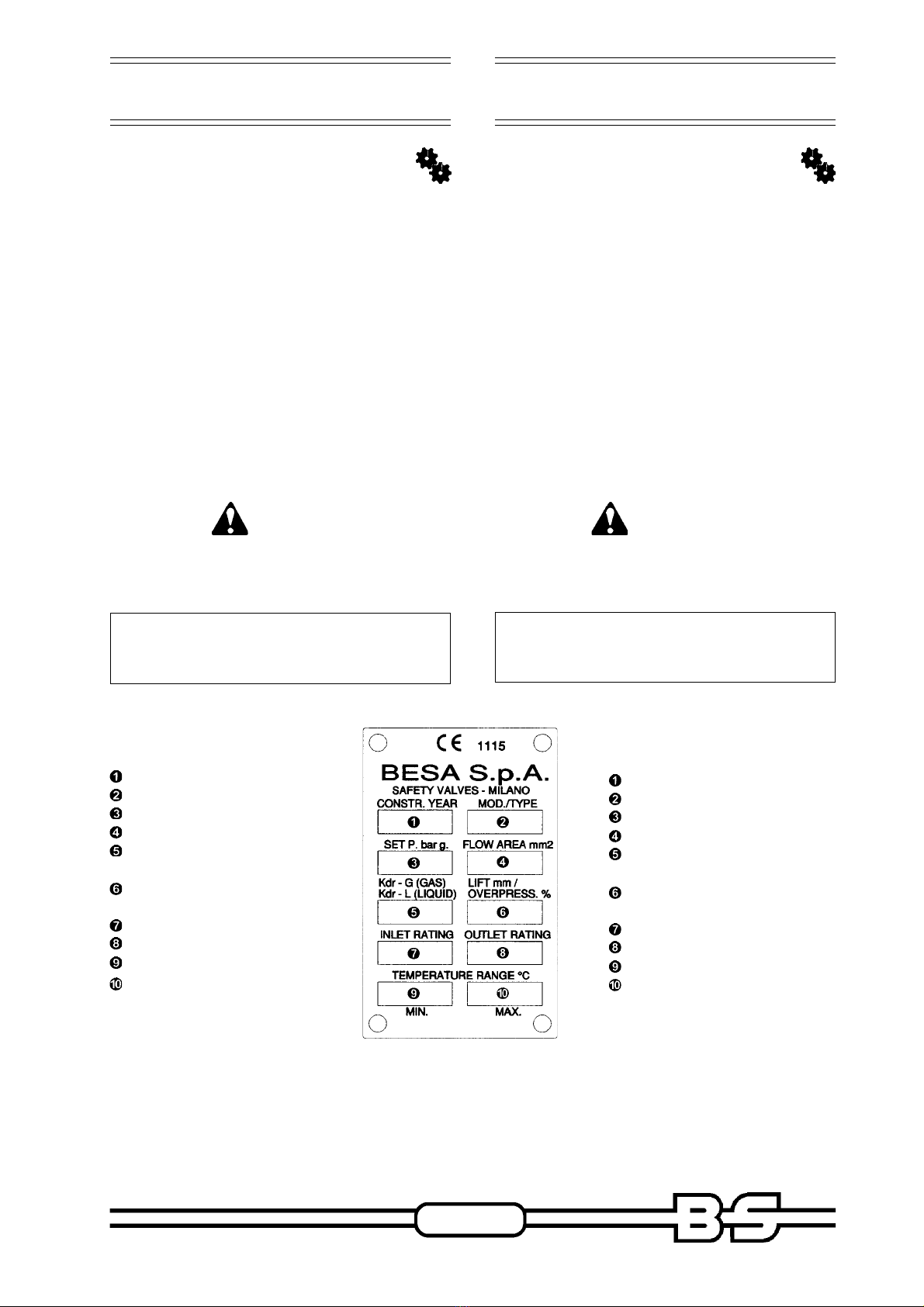
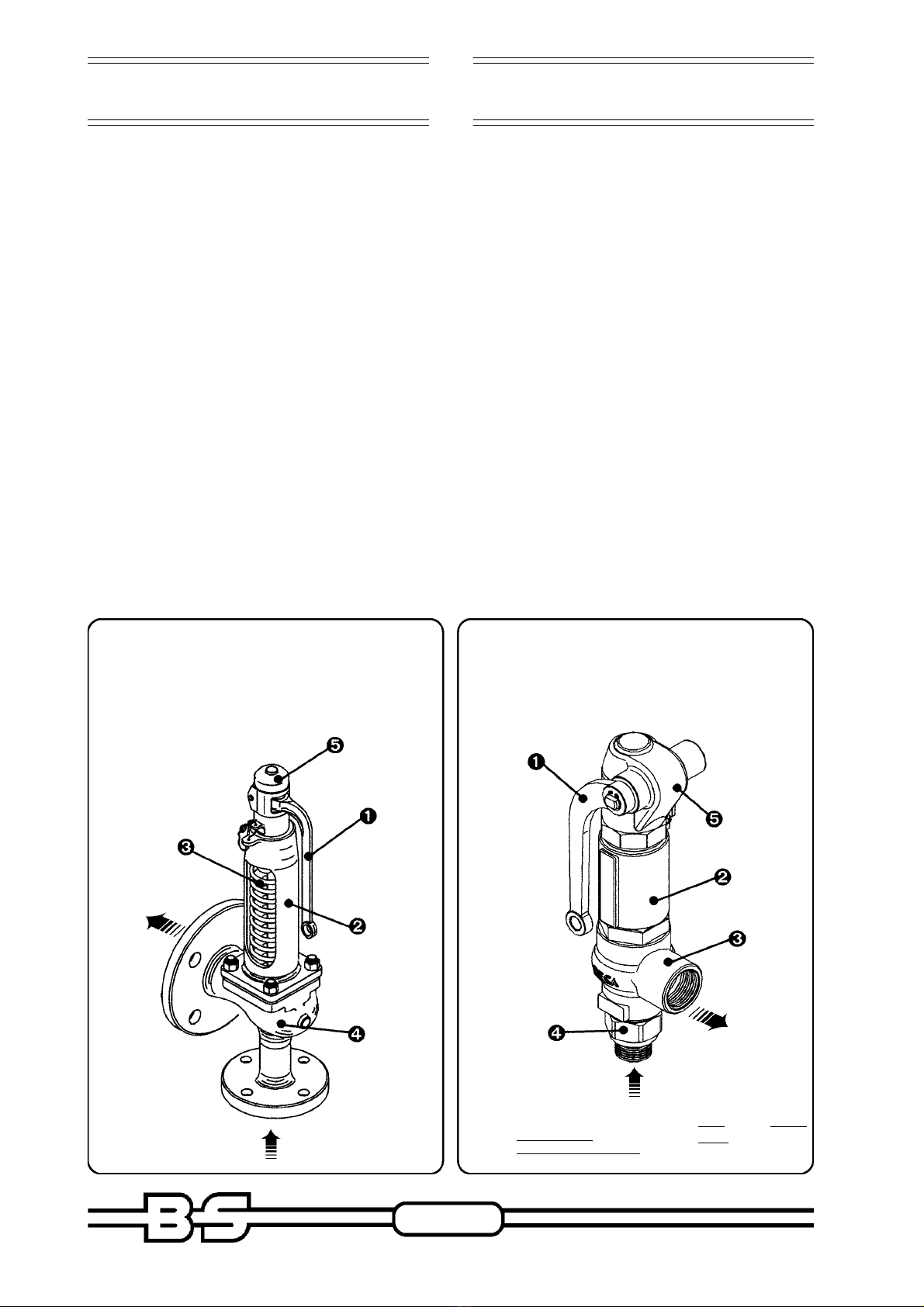
2DESCRIPTION OF THE VALVE ............... 7
2.1 DATA OF THE VALVE ................................ 7
2.2 GENERAL FEATURES .............................. 8
2.3 TYPE 241- 242 .......................................... 9
2.4 TYPE 241- 242 DN 200-250 .................... 10
2.5 TYPE 241F - 242F ................................... 11
2.6 TYPE 131 - 132 ....................................... 12
2.7 TYPE 251 - 252 ....................................... 13
2.8 TYPE 261 - 262 ....................................... 14
2.9 TYPE 139 ................................................ 15
2.10 TYPE 249 ................................................ 16
2.11 TYPE 271 ................................................ 17
3INSTALLATION ............................................... 18
3.1 GOODS
CHECKING ............................................ 18
3.2 INSTALLATION PROCEDURES .............. 19
3.3 INSTALLATION OF THE VALVE ............... 20
4SAFETY VALVE OPERATION ................ 23
4.1 OPERATING PRESSURE ....................... 23
4.2 SOFT TIGHTNESS ................................. 23
4.3 PRESSURE LOSS ................................. 24
4.4 HARMFUL OR DANGEROUS
MEDIUMS ............................................... 24
4.5 INSPECTION OF TIGHTNESS ..............25
4.6 MEDIUM AT HIGH TEMPERATURE ...... 25
4.7 CRYSTALLIZATION / POLYMERIZATION
OF MEDIUM ........................................... 25
4.8 MEDIUM LEAKAGE ............................... 26
5MAINTENANCE ...................................... 27
5.1 GENERAL INFORMATION ..................... 27
5.2 SAFETY INSTRUCTIONS ...................... 27
5.3 CLOTHING ............................................. 28
5.4 ORDINARY MAINTENANCE .................. 28
5.5 CLEANING AND LUBRICATION ............ 28
5.6 PRESSURE ADJUSTMENT ................... 29
5.7 SPRING REPLACEMENT ...................... 39
5.8 CUSTOMER CARE SERVICE ............... 42
5.9 SPARE PARTS LIST .............................. 42
6DISMANTLING ....................................... 43
6.1 STORAGE .............................................. 43
6.2 DISMANTLING PROCEDURES ............. 43
ÍNDICE GENERAL
USO DEL MANUAL ............................................ 3
SÍMBOLOS EMPLEADOS ................................. 3
CARTAINFORMATIVA ....................................... 4
GARANTÍA ......................................................... 5
1TRANSPORTE Y
DESPLAZAMIENTO .................................. 6
2DESCRIPCIÓN DE LA VÁLVULA ............ 7
2.1 DATOS DE LAVÁLVULA ........................... 7
2.2 CARACTERÍSTICAS GENERALES ........... 8
2.3 MOD. 241- 242 .......................................... 9
2.4 MOD.241- 242 DN 200-250 ..................... 10
2.5 MOD.241F - 242F .................................... 11
2.6 MOD.131 - 132 ........................................ 12
2.7 MOD.251 - 252 ........................................ 13
2.8 MOD.261 - 262 ........................................ 14
2.9 MOD.139 ................................................. 15
2.10 MOD.249 ................................................. 16
2.11 MOD.271 ................................................. 17
3INSTALACIÓN ................................................ 18
3.1 CONTROL DEL PRODUCTO
COMPRADO ........................................... 18
3.2 CONDICIONES PARA LAINSTALACIÓN .... 19
3.3 INSTALACIÓN DE LAVÁLVULA ............... 20
4SERVICIO DE LA VÁLVULA DE
SEGURIDAD ........................................... 23
4.1 PRESIÓN DE SERVICIO ........................ 23
4.2 HERMETICIDAD SUAVE ......................... 23
4.3 PÉRDIDAS DE CARGA .......................... 24
4.4 FLUIDOS NOCIVOS O PELIGROSOS ....... 24
4.5 CONTROL DE HERMETICIDAD ............. 25
4.6 FLUIDO AALTA TEMPERATURA ............ 25
4.7 CRISTALIZACIÓN/POLIMERIZACIÓN
DEL FLUIDO ........................................... 25
4.8 PÉRDIDA DE FLUIDO ............................ 26
5MANTENIMIENTO ................................... 27
5.1 INFORMACIONES GENERALES ............ 27
5.2 NORMAS DE SEGURIDAD ..................... 27
5.3 VESTIMENTA ......................................... 28
5.4 MANTENIMIENTO ORDINARIO ............ 28
5.5 LIMPIEZA Y LUBRICACIÓN ................... 28
5.6 REGULACIÓN DE LA PRESIÓN ........... 29
5.7 SUSTITUCIÓN DEL RESORTE ............. 39
5.8 ASISTENCIA TÉCNICA .......................... 42
5.9 LISTA PIEZAS DE RECAMBIO .............. 42
6DESGUACE ............................................ 43
6.1 ALMACENAMIENTO ................................ 43
6.2 PUESTA FUERA DE SERVICIO .............. 43

USE AND MAINTENANCE
MANUAL
USE AND MAINTENANCE
MANUAL
Pag. 3 / 49
MANUAL DE USO Y
MANTENIMIENTO
MANUAL DE USO Y
MANTENIMIENTO
HOW TO USE THIS MANUAL
The use and maintenance manual can be
considered as an integral part of the valve and,
as such, it should be kept with it up to the
moment of the dismantlement.
Please read this manual carefully before
handling, moving or even unloading the
purchased product.
In order to make your reading much easier, this
manual has been edited in chapters. Please find
following a list of the different sections:
Section
Packing, moving and transport.
Section
Description and use of the valve. In this section
you will also find the technical specifications of
the product.
Section
Checking of the product and installation.
Section
Standard operating cycle of the valve when mounted
on the system.
Section
Ordinary and extraordinary maintenance and
description of safety precautions against
accidents which might occur when working close
to the system.
Section
Dismantlement
Annexes
SYMBOLS
The following symbol will draw your attention on
possible misuses or wrong operating
procedures:
USO DEL MANUAL
El manual de uso y mantenimiento es el documento
que acompaña la válvula desde el momento de su
fabricación hasta el de su desguace y reciclaje,
por lo que constituye parte integrante de la misma.
Es necesario haber leído el manual antes de efectuar
CUALQUIER ACTIVIDAD relativa a la válvula,
incluido su traslado y descarga desde el medio de
transporte.
A fin de facilitar su consulta, el manual ha sido
dividido en las siguientes secciones:
Sección
Embalaje, desplazamiento y transporte.
Sección
Descripción de la válvula y del respectivo campo
de aplicación. Se ilustran además todas las
características técnicas de la válvula.
Sección
Control del producto comprado e instalación de la
válvula en el sistema.
Sección
Funcionamiento normal de la válvula durante el
servicio dentro del sistema.
Sección
Mantenimiento ordinario, extraordinario y
descripción de los sistemas de protección
adoptados a fin de garantizar la incolumidad de
las personas que operan en proximidad de la
válvula.
Sección
Desguace
Anexos
SÍMBOLOS EMPLEADOS
Las operaciones que pueden comportar riesgos en
caso de no ser correctamente efectuadas son
indicadas mediante el símbolo:

USE AND MAINTENANCE
MANUAL
USE AND MAINTENANCE
MANUAL
Pag. 4 / 49
MANUAL DE USO Y
MANTENIMIENTO
MANUAL DE USO Y
MANTENIMIENTO
The following symbol will underline that qualified
and skilled workers are required:
The supplier recommends that workers in charge
of the installation and maintenance of the valve
should be trained properly.
The maintenance of the safety valve must be
carried out by BESA personnel or by BESA
authorized personnel
ADDITIONAL INFORMATION
Workers in charge of the operation and
maintenance of the valve should study and
always refer to the instructions described in the
present manual, which should be considered as
an integral part of the valve.
Provided that the basic specifications of the
described valve cannot be varied, BESA will feel
free to make changes in order to improve the
product any time without updating this manual.
Changes could be also made because of
technical reasons or for commercial purposes.
This manual confirms the technical requirements
to sell the safety valve.
NOTICE
ALL RIGHTS RESERVED, information and
descriptions included in this manual are
copyright and cannot be published, not even
partially, without formal authorization from
BESA Ing. Santangelo S.p.A.
Las operaciones que deben ser efectuadas por
personal calificado o especializado son indicadas
mediante el símbolo:
Se recomienda capacitar al personal encargado
de efectuar la instalación.
El mantenimiento de la válvula de seguridad debe
ser efectuado por personal BESA o por personal
por ella autorizado.
CARTA INFORMATIVA
El presente manual de uso y mantenimiento
constituye parte integrante de la válvula por lo que
debe mantenerse a disposición para su consulta
de parte del personal encargado del uso y del
mantenimiento de la misma.
El usuario y el encargado del mantenimiento tienen
la obligación de conocer el contenido del presente
manual.
Manteniendo inalteradas las características
esenciales del tipo de válvula descrita, BESA se
reserva el derecho de incorporar las modificaciones
a órganos, detalles y accesorios que considere
convenientes para la mejora del producto o por
requerimientos de su fabricación o comer-
cialización, en todo momento y sin obligación de
actualizar tempestivamente esta publicación. El
manual refleja el nivel y estado de la técnica aplicada
en el momento de la comercialización de la válvula.
ATENCIÓN
QUEDAN RESERVADOS TODOS LOS
DERECHOS y queda prohibida la reproducción
de cualquier parte de este manual, en cualquier
forma, sin el explícito permiso escrito de BESA
Ing. Santangelo S.p.A.
El contenido de este manual puede ser
modificado sin aviso previo.

USE AND MAINTENANCE
MANUAL
USE AND MAINTENANCE
MANUAL
Pag. 5 / 49
MANUAL DE USO Y
MANTENIMIENTO
MANUAL DE USO Y
MANTENIMIENTO
For any further information, please contact BESA
Customer Care Service at the following address:
WARNING
The original specifications of the valve must
not be changed.
All rights of the drawing and of any other
document delivered with product are reserved.
WARRANTY
Besa products are guaranteed for 12 months from
the date of the shipment (however according to the
law in force).
The supplier will guarantee the free replacement of
any part claimed as defective. The warranty will not
cover damages caused by misuses, wear or dirt.
Any compliant regarding the quantity or quality of
the delivery will have to be reported in writing within
10 days from the date of delivery.
SERVICIO DE ASISTENCIA TÉCNICA / CUSTOMER CARE SERVICE
Via Donatello, 31 - 2031 MILANO
Tel. +39-02.70.63.47.20 r.a. - Fax. +39-02.23.63.996
E-mail: [email protected]
Respecto de cualquier problema o para solicitar
mayores informaciones sírvase contactar con el
servicio de asistencia técnica BESA utilizando la
siguiente dirección:
ATENCIÓN
No deberá modificarse en absoluto la
configuración original de la válvula.
Los dibujos y todos los restantes documentos
entregados son de propiedad BESA -la que se
reserva los respectivos derechos- y no pueden ser
puestos a disposición de terceros.
GARANTÍA
Los productos BESA cuentan con garantía por un
período de 12 meses (en cualquier caso según lo
establecido por la normativa vigente) a partir del
día en que se efectúa el suministro.
Todas las piezas que resulten defectuosas sea por
material sea por elaboración, serán sustituidas
gratuitamente, en nuestro establecimiento.
Las solicitudes en cuanto a sustitución de piezas
dañadas por desgaste, suciedad, manipulaciones
impropias, etc., serán rechazadas por BESA, así
como ulteriores solicitudes de garantías
contractuales.
Todo reclamo relativo a la mercancía recibida tanto
por cantidad como por ejecución diferente de la
solicitada, deberá dirigirse por escrito a BESA como
máximo dentro de los 10 días sucesivos a la
recepción del material.

USE AND MAINTENANCE
MANUAL
USE AND MAINTENANCE
MANUAL
Pag. 6 / 49
MANUAL DE USO Y
MANTENIMIENTO
MANUAL DE USO Y
MANTENIMIENTO
1TRANSPORT AND
HANDLING
BESA safety valves can be either moved without
packing, or placed in wooden containers
according to their dimensions.
Valves can be moved more easily
when placed on a bench.
WARNING
Use protective gloves and
accident prevention shoes when
moving the valve.
WARNING
In order to prevent possibile accidents or damages
when moving the valve, people or animals should be
kept at safety distance.
Should the valve need to be installed
or moved inside the system, use a
hand truck or a fork truck.
WARNING
Follow the instructions on the packing before
handling.
STROKES AND VIBRATIONS CAN
DAMAGE THE VALVE, THAT THEREFORE
SHOULD BE HANDLED WITH CARE.
REMOVE THE FLANGES PROTECTIONS
AGAINST DIRTY AT THE MOMENT OF
INSTALLATION ONLY.
1TRANSPORTE Y
DESPLAZAMIENTO
Las válvulas de seguridad BESA, según cuáles sean
sus dimensiones, pueden ser transportadas sin
embalaje o bien colocadas en
cajones de madera.
Para facilitar su desplazamiento es
conveniente fijar el embalaje a una
paleta.
ATENCIÓN
El personal encargado de la
manipulación de la carga debe
operar con guantes y calzado de
protección contra accidentes.
ATENCIÓN
Al elevar o trasladar la válvula despejar y mantener
libre la zona de operaciones, dejando también libre
en torno a ella una zona de seguridad suficiente a
fin de evitar daños a personas,
animales u objetos que puedan
encontrarse dentro del radio de
maniobra.
En caso de que sea necesario
trasladar y posicionar la válvula en
el interior del establecimiento deberá
emplearse un carro manual, o bien,
cuando se trate de válvulas de
grandes dimensiones, una carretilla
elevadora provista de horquillas.
ATENCIÓN
Es necesario seguir todas las instrucciones
indicadas en el embalaje antes de abrirlo.
VIBRACIONES Y GOLPES PUEDEN DAÑAR
LA VÁLVULA, QUE POR LO TANTO DEBE
SER TRATADA CON CUIDADO.
RETIRAR LAS PROTECCIONES DE LAS
BRIDAS QUE IMPIDEN LA ENTRADA DE
IMPUREZAS SÓLO EN EL MOMENTO DE
INSTALAR LA VÁLVULA EN EL SISTEMA.

USE AND MAINTENANCE
MANUAL
USE AND MAINTENANCE
MANUAL
Pag. 7 / 49
MANUAL DE USO Y
MANTENIMIENTO
MANUAL DE USO Y
MANTENIMIENTO
2. DESCRIPTION OF THE
VALVE
2.1 DATA OF THE VALVE
The identification label shown below is placed
on the bonnet of the valve, where the serial
number and the set pressure value are printed
on the body.
In relief the casting number and the material
specifications.
When contacting the supplier, please always
mention the serial number.
The supplier is not responsible for accidents or
damages due to negligence. The operator is
therefore supposed to follow the instructions
being responsible in case of dispute.
WARNING
The label, the lead seal and the printed data must
not be removed or changed, even if the valve
has to be sold to someone else.
The safety valve data are written on the
test certificate
2. DESCRIPCIÓN DE LA
VÁLVULA
2.1 DATOS DE LA VÁLVULA
La placa de identificación del fabricante abajo
ilustrada está colocada en el sombrerete de la
válvula de seguridad.
Además, en el cuerpo de la válvula están estampados
los datos relativos al número de matrícula y al valor
de la presión de calibración; en relieve se indican
el número de colada y la identificación del material
de fabricación.
Para toda comunicación con el fabricante deberá
indicarse siempre el número de matrícula.
ATENCIÓN
Por ningún motivo deberán retirarse ni modificarse
la placa, el sello de plomo ni los datos estampados,
ni siquiera en caso de reventa del equipo.
Los datos específicos de la válvula de
seguridad se indican en el certificado de la
prueba final de funcionamiento.
Leyenda placa
Año de fabricación
Modelo válvula
Presión de calibración
Área del agujero
Coeficiente de flujo
gas/líquidos
Elevación obturador/
Sobrepresión
Rating lado entrada
Rating lado salida
Temperatura mín. de uso
Temperatura máx. de uso
Plate Key
Construction year
Valve type
Set pressure
Flow area
Coefficient
of flow gas/liquid
Disc lift
Overpressure
Inlet rating
Outlet rating
Min. temperature of use
Max. temperature of use

USE AND MAINTENANCE
MANUAL
USE AND MAINTENANCE
MANUAL
Pag. 8 / 49
MANUAL DE USO Y
MANTENIMIENTO
MANUAL DE USO Y
MANTENIMIENTO
2.2 GENERAL FEATURES
Safety valves are emergency discharge devices for
fluids under pressure. They act automatically as
soon as the set pressure is reached.
These valves have to be projected according to
specific national and international standards.
They have to be dimensioned, tested and installed
according to the present rules and to what is
specified in this manual.
BESA safety valves are the result of great experience
gained in several fields from year to year. They
fulfill all the safety requirements of pressure systems.
They can ensure that the maximum pressure valued
allowed does not exceed the limit, even if the other
safey devices of the system have not worked
properly.
In the following picture you will find a list of the most
important parts of the safety valve
Note: Cap and outlet
body of type 249
are separated
1 ➠Lifting lever
2 ➠Bonnet
3 ➠Spring
4 ➠Body
5 ➠Cap
DESCARGA
DISCHARGE
ENTRADA FLUIDO
MEDIUM INLET
1 ➠Lifting lever
2 ➠Bonnet
3 ➠Outlet body
4 ➠Inlet body
5 ➠Cap
DESCARGA
DISCHARGE
ENTRADA FLUIDO
MEDIUM INLET
2.2 CARACTERÍSTICAS
GENERALES
Las válvulas de seguridad son dispositivos de descarga
de emergencia para fluidos a presión, idóneos para
intervenir automáticamente al alcanzarse la presión de
calibración.
Estas válvulas cumplen con lo dispuesto por específicas
normas nacionales e internacionales, por lo tanto deben
ser dimensionadas, probadas, instaladas y mantenidas
de conformidad con lo establecido por las normas
vigentes y aplicando las instrucciones del presente
manual.
Las válvulas de seguridad BESA son el resultado de
una gran experiencia, acumulada a lo largo de décadas
de aplicación en diferentes campos y satisfacen
ampliamente todos los requisitos como última
salvaguardia de los aparatos a presión.
Están perfectamente en condiciones de impedir que el
aumento de presión supere el valor máximo admitido,
incluso en caso de bloqueo de todos los restantes
dispositivos autónomos de seguridad instalados en
posición previa.
Algunos de los principales componentes de la válvula
de seguridad aparecen ilustrados en la figura:
1 ➠Palanca de elevación
2 ➠Sombrerete
3 ➠Resorte
4 ➠Cuerpo válvula
5 ➠Capuchón
NOTA: En el modelo 249 el
sombrerete y el
cuerpo de salida
están separados.
1 ➠Palanca de elevación
2 ➠Sombrerete
3 ➠Cuerpo de salida
4 ➠Cuerpo de entrada
5 ➠Capuchón

USE AND MAINTENANCE
MANUAL
USE AND MAINTENANCE
MANUAL
Pag. 9 / 49
MANUAL DE USO Y
MANTENIMIENTO
MANUAL DE USO Y
MANTENIMIENTO
2.3 SPECIFICATIONS
Type 241- 242
Mod. 241 sombrerete cerrado
Type 241 Closed bonnet
Mod. 242 sombrerete abierto
Type 242 Open bonnet
Capuchón H2 hermético
Tight Cap H2
Capuchón H3 no hermético con
palanca de elevación
Open Cap H3
with lifting lever
Capuchón H4 hermético con
palanca de elevación
Tight Cap H4
with lifting lever
.FER etnenopmoC .traP
1opreuC ydoB
2otneisA taeS
3rodarutbO csiD
4aíugedollitalP ediugetelpmoC
5etererbmoS tennoB
6atsA eldnipS
7arapesabedsetenijoC
etroser
etalpgnirpS
8nóicarbilacedollinroT wercserusserP
9etroseR gnirpS
01aloB llaB
11nóhcupaC paC
2.3 CARACTERÍSTICAS
Mod. 241-242

USE AND MAINTENANCE
MANUAL
USE AND MAINTENANCE
MANUAL
Pag. 10 / 49
MANUAL DE USO Y
MANTENIMIENTO
MANUAL DE USO Y
MANTENIMIENTO
2.4 SPECIFICATIONS
Type 241- 242 DN 200-250
.FER etnenopmoC .traP
1adartneedopreuC ydobtelnI
2adilasedopreuC ydobteltuO
3otneisA taeS
4rodarutbO csiD
5aíugedollitalP ediugetelpmoC
6etererbmoS tennoB
7atsA eldnipS
8arapesabedsetenijoC
etroser
etalpgnirpS
9nóicarbilacedollinroT wercserusserP
01etroseR gnirpS
11aloB llaB
21nóhcupaC paC
2.4 CARACTERÍSTICAS
Mod. 241- 242 DN 200-250
Capuchón H2 hermético
Tight Cap H2
Capuchón abierto H3 con
palanca de elevación
Open Cap H3
with lifting lever
Capuchón H4 hermético con
palanca de elevación
Tight Cap H4
with lifting leverMod. 241 sombrerete cerrado
Type 241 Closed bonnet
Mod. 242 sombrerete abierto
Type 242 Open bonnet

USE AND MAINTENANCE
MANUAL
USE AND MAINTENANCE
MANUAL
Pag. 11 / 49
MANUAL DE USO Y
MANTENIMIENTO
MANUAL DE USO Y
MANTENIMIENTO
2.5 SPECIFICATIONS
Type 241F – 242F
2.5 CARACTERÍSTICAS
Mod. 241F – 242F
Mod. 241F sombrerete cerrado
Type 241F Closed bonnet
Mod. 242F sombrerete abierto
Type 242F Open bonnet
Capuchón H2 hermético
Tight Cap H2
Capuchón H3 con
palanca de elevación
Open Cap H3
with lifting lever
Capuchón H4 hermético
con palanca de elevación
Tight Cap H4
with lifting lever
.FER etnenopmoC .traP
1opreuC ydoB
2otneisA taeS
3rodarutbO csiD
4aíugedollitalP ediugetelpmoC
5etererbmoS tennoB
6atsA eldnipS
7arapesabedsetenijoC
etroser
etalpgnirpS
8nóicarbilacedollinroT wercserusserP
9etroseR gnirpS
01aloB llaB
11nóhcupaC paC

USE AND MAINTENANCE
MANUAL
USE AND MAINTENANCE
MANUAL
Pag. 12 / 49
MANUAL DE USO Y
MANTENIMIENTO
MANUAL DE USO Y
MANTENIMIENTO
2.6 SPECIFICATIONS
Type 131 – 132
Capuchón H2 hermético
Tight Cap H2
Capuchón H3 abierto con
palanca de elevación
Open Cap H3
with lifting lever
Capuchón H4 hermético con
palanca de elevación
Tight Cap H4
with lifting lever
2.6 CARACTERÍSTICAS
Mod. 131 – 132
Mod. 131 sombrerete cerrado
Type 131 Closed bonnet
Mod. 132 sombrerete abierto
Type 132 Open bonnet
.FER etnenopmoC .traP
1opreuC ydoB
2otneisA taeS
3rodarutbO csiD
4aíugedollitalP ediugetelpmoC
5etererbmoS tennoB
6atsA eldnipS
7arapesabedsetenijoC
etroser
etalpgnirpS
8nóicarbilacedollinroT wercserusserP
9etroseR gnirpS
01aloB llaB
11nóhcupaC paC

USE AND MAINTENANCE
MANUAL
USE AND MAINTENANCE
MANUAL
Pag. 13 / 49
MANUAL DE USO Y
MANTENIMIENTO
MANUAL DE USO Y
MANTENIMIENTO
2.7 SPECIFICATIONS
Type 251 - 252
.FER etnenopmoC .traP
1opreuC ydoB
2otneisA taeS
3rodarutbO csiD
4aíugedollitalP ediugetelpmoC
5etererbmoS tennoB
6atsA eldnipS
7arapesabedsetenijoC
etroser
etalpgnirpS
8nóicarbilacedollinroT wercserusserP
9etroseR gnirpS
01aloB llaB
11epotedlaixaotneimadoR gniraeB
21nóhcupaC paC
2.7 CARACTERÍSTICAS
Mod. 251 - 252
Capuchón H2 hermético
Tight Cap H2
Capuchón H3 abierto con
palanca de elevación
Open Cap H3
with lifting lever
Capuchón H4 hermético con
palanca de elevación
Tight Cap H4
with lifting lever
Mod. 251 sombrerete cerrado
Type 251Closed bonnet
Mod. 252 sombrerete abierto
Type 252 Open bonnet

USE AND MAINTENANCE
MANUAL
USE AND MAINTENANCE
MANUAL
Pag. 14 / 49
MANUAL DE USO Y
MANTENIMIENTO
MANUAL DE USO Y
MANTENIMIENTO
2.8 SPECIFICATIONS
Type 261 -262
.FER etnenopmoC .traP
1opreuC ydoB
2alliuqoB elzzoN
3rodarutbO csiD
4aíugedollitalP ediuG
5etererbmoS tennoB
6atsA eldnipS
7arapesabedsetenijoC
etroser
etalpgnirpS
8nóicarbilacedollinroT wercserusserP
9etroseR gnirpS
01aloB llaB
11epotedlaixaotneimadoR gniraeB
21nóhcupaC paC
2.8 CARACTERÍSTICAS
Mod. 261 -262
Mod. 261 sombrerete cerrado
Type 261Closed bonnet
Mod. 262 sombrerete abierto
Type 262 Open bonnet
Capuchón H2 hermético
Tight Cap H2
Capuchón H3 abierto con
palanca de elevación
Open Cap H3
with lifting lever
Capuchón H4 hermético con
palanca de elevación
Tight Cap H4
with lifting lever

USE AND MAINTENANCE
MANUAL
USE AND MAINTENANCE
MANUAL
Pag. 15 / 49
MANUAL DE USO Y
MANTENIMIENTO
MANUAL DE USO Y
MANTENIMIENTO
2.9 SPECIFICATIONS
Type 139
Válvula mod. 139
Valve type 139
Capuchón H3 abierto con
obturador elevable
No gastight cap H3
with lifting disc
Capuchón H4 hermético con
obturador elevable
Tight Cap H4
with lifting disc
.FER etnenopmoC .traP
1adartneedopreuC ydobtelnI
2sadaepalnóicneteredseicifrepusnocrodarutbO secafrusthgitsagdeppalhtiwcsiD
3aloB llaB
4olliuqsaC gnihsuB
5aíugedollitalP ediugetelpmoC
6etroseR gnirpS
7atsA eldnipS
8etererbmoS tennoB
9nóicarbilacedollinroT wercserusserP
01nóhcupaC paC
2.9 CARACTERÍSTICAS
Mod. 139
Capuchón H2 hermético
Tight Cap H2

USE AND MAINTENANCE
MANUAL
USE AND MAINTENANCE
MANUAL
Pag. 16 / 49
MANUAL DE USO Y
MANTENIMIENTO
MANUAL DE USO Y
MANTENIMIENTO
2.10 SPECIFICATIONS
Type 249
Válvula mod. 249
Valve type 249
.FER etnenopmoC .traP
1adartneedopreuC ydobtelnI
2sadaepalnóicneteredseicifrepusnocrodarutbO secafrusthgitsagdeppalhtiwcsiD
3aloB llaB
4adilasedopreuC gnihsuB
5aíugedollitalP ediugetelpmoC
6etererbmoS tennoB
7atsA eldnipS
8etroseR gnirpS
9nóicarbilacedollinroT wercserusserP
01nóhcupaC paC
2.10 CARACTERÍSTICAS
Mod. 249
Capuchón H2 hermético
Tight Cap H2
Capuchón H3 no hermético
con palanca de elevación
Open Cap H3
with lifting lever
Capuchón H4 hermético
con palanca de elevación
Tight Cap H4
with lifting lever

USE AND MAINTENANCE
MANUAL
USE AND MAINTENANCE
MANUAL
Pag. 17 / 49
MANUAL DE USO Y
MANTENIMIENTO
MANUAL DE USO Y
MANTENIMIENTO
2.11 SPECIFICATIONS
Type 271
Válvula mod. 271
Valve type 271
.FER etnenopmoC .traP
1adartneedopreuC ydoBtelnI
2adilasedopreuC ydoBteltuO
3otneimitseveR gniniL
4rodaugitromaopreucyrodarutbO ydobcitsalednacsiD
5aíugedollitalP ediugetelpmoC
6etererbmoS tennoB
7atsA eldnipS
8etroserarapesabedsetenijoC etalpgnirpS
9nóicarbilacedollinroT wercserusserP
01etroseR gnirpS
11aloB llaB
21nóhcupaC paC
Capuchón H2 hermético
Tight Cap H2
Capuchón H4 hermético
con palanca de elevación
Tight Cap H4
with lifting lever
2.11 CARACTERÍSTICAS
Mod. 271

USE AND MAINTENANCE
MANUAL
USE AND MAINTENANCE
MANUAL
Pag. 18 / 49
MANUAL DE USO Y
MANTENIMIENTO
MANUAL DE USO Y
MANTENIMIENTO
3. INSTALLATION
3.1 GOODS CHECKING AND
LIFTING METHOD
Upon receipt of the goods, please check that:
-packing has not been damaged;
-items have been supplied according to the
specifications mentioned on the order form
(see the delivery note).
Ensure that the valve has not been damaged
during the carriage and remove the packing (if
not otherwise suggested by BESA).
Should you determine the product is defective,
please contact the supplier within 10 days from
the date of receiving.
CAUTION
Check that the lead sealing has not been
damaged. (see pict. 1)
3.1.1 LIFTING
The safety valve must be suitably slinged. It is
necessary to pay attention to the sling because
it must avoid the unhooking and the turnover of
the valve during the lifting and the moving
operations of the safety valve. (see pict. 2)
fig. 1
pict. 1
fig. 2
pict. 2
3. INSTALACIÓN
3.1 CONTROL DEL PRODUCTO
COMPRADO Y MODALIDAD DE
ELEVACIÓN
Al recibirse el suministro se deberá verificar que:
-los embalajes estén íntegros y no presenten
daños;
-el suministro corresponda a las especificaciones
del pedido (véase albarán o lista de contenido).
Una vez verificada la integridad del suministro retirar
el embalaje (salvo en los casos en que BESA haya
dado indicaciones en contrario) y verificar que la
válvula no presente daños derivados del
transporte.
En caso de verificarse daños o anomalías la
respectiva comunicación deberá efectuarse
dentro de los diez días sucesivos a la recepción
de la válvula.
ATENCIÓN
Verificar que el sello de plomo no haya
sufrido daños (véase fig. 1).
3.1.1 ELEVACIÓN
Para elevar la válvula se la deberá amarrar
adecuadamente.
Es necesario prestar máxima atención a fin de que
las ligaduras impidan que la válvula se
desenganche y se vuelque Durante las maniobras
de elevación y desplazamiento de la misma (véase
fig. 2) .

USE AND MAINTENANCE
MANUAL
USE AND MAINTENANCE
MANUAL
Pag. 19 / 49
MANUAL DE USO Y
MANTENIMIENTO
MANUAL DE USO Y
MANTENIMIENTO
3.2 INSTALLATION
PROCEDURES
CAUTION
We prescribe that the valve should only
be installed by SKILLED STAFF PEOPLE
who should always refer to this manual.
➠The materials of the valve need to be suitable
both to the nature and state of the fluids to
discharge, and to external environmental
conditions;
➠check that the connections are in accordance
with the specifications of the system where
the valve has to be installed; particularly when
dimensioning the inlet pipe, take into
consideration the forces and moments
deriving from the passage of the fluid inside
the valve;
➠in order to avoid serious injuries, when
discharging in the atmosphere ensure to
direct the valve properly;
➠when installing the valve, ensure that the
bonnet is mounted upright;
➠according to the installation, put special
indications (warning notices) to inform about
the risks caused by the movement of the trims
(i.e. spring) and by the exercise temperature.
3.2 CONDICIONES PARA
LA INSTALACIÓN
ATENCIÓN
La instalación de la válvula debe ser
efectuada únicamente por PERSONAL
CALIFICADO y que haya leído con atención
el presente manual.
➠En los sistemas deben instalarse válvulas
cuyos materiales de fabricación sean
adecuados para trabajar en las condiciones
previstas (naturaleza y estado físico del fluido,
ambiente externo).
➠Verificar que las conexiones de las válvulas
de seguridad correspondan a las
especificaciones del sistema en el que deben
ser instaladas; en particular por lo que se
refiere al dimensionamiento de la brida de
conexión de la válvula, deben tomarse en
consideración las fuerzas y los momentos
generados por el paso del fluido a través de
la válvula misma.
➠Si la descarga se efectúa en la atmósfera, la
válvula debe ser dirigida de manera tal que no
provoque lesiones a las personas ni daños a las
cosas.
➠Instalar la válvula con el sombrerete en
posición vertical y dirigido hacia arriba.
➠En función de las características de cada
instalación se deberán aplicar indicaciones
específicas (carteles) que informen acerca de
los riesgos residuales presentes en los órganos
móviles (movimiento) y respecto de la
temperatura de servicio.

USE AND MAINTENANCE
MANUAL
USE AND MAINTENANCE
MANUAL
Pag. 20 / 49
MANUAL DE USO Y
MANTENIMIENTO
MANUAL DE USO Y
MANTENIMIENTO
3.3 INSTALACIÓN DE LA VÁLVULA
Prestando atención a fin de no dañar la superficie,
retirar las protecciones y montar la válvula de
acuerdo con las especificaciones del sistema.
Cuando la descarga está conectada a una
tubería externa deberá instalarse una guarnición
entre las bridas.
3.3.1 TUBERÍAS DE CONEXIÓN DE LA
VÁLVULA DE SEGURIDAD
Las tuberías de conexión en entrada y aquéllas de
conducción de la descarga en salida, pueden
transmitir -con válvula tanto cerrada como en fase
de descarga- tensiones estáticas, dinámicas y
térmicas capaces de afectar la estabilidad de la
válvula de seguridad.
Por lo tanto, las tuberías deben ser proyectadas,
fabricadas e instaladas a fin de evitar que la válvula
de seguridad sufra el efecto de tensiones
adicionales respecto de aquéllas determinadas por
la presión interna y por el apriete.
3.3 INSTALLATION OF THE VALVE
Handle with care in order not to damage the
surface, remove protections and install the valve
according to the specifications of the system.
When the outlet flange is connected to an
external piping, it would be necessary to insert a
gasket as shown in the picture.
3.3.1 PIPES OF CONVEYANCE OF
SAFETY VALVES
In case of closing or opening phases, the pipes
can transmit static, dynamic and thermal
stresses, which can compromise the stability of
the safety valve.
The pipes must be designed, constructed and
installed in order not to cause further stresses
to the safety valve, as well as those caused by
the inlet pressure and by the clamping.
Tubería de
entrada
Inlet
pipe
Tuercas de fijación
Fixing screws
Brida tubería de
descarga
Discharge pipe flange Guarnición
Gasket
Tubería de
salida
Outlet
pipe
This manual suits for next models
12
Table of contents
Other BESA Control Unit manuals
Popular Control Unit manuals by other brands

Tibbo
Tibbo EM1000 Programmable Hardware Manual

SetonixSynth
SetonixSynth Doug Assembly

SSP
SSP 100 Series Maintenance instructions

ABB
ABB REF 542plus Operator's manual

Task Force Tips
Task Force Tips G-Force G A Series manual

Cabletron Systems
Cabletron Systems SmartSwitch 9500 Hardware and installation guide