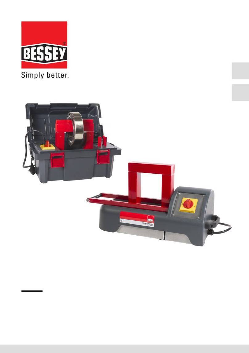
Bessey SBH Series User manual

FR
EN
© Bessey Tools - 23.06.R03
USER MANUAL
Bessey Smart Induction Heaters
SBH series


Warning!
Read the manual and safety instructions before operating the device
• Check all parts for possible damage during transportation. In case of damage, please
contact the forwarder immediately.
• Because our products are continuously subject to improvements, we reserve the right
to make changes.
Vor Inbetriebnahme die Betriebsanleitung und die Sicherheitsvorschriften
aufmerksam lesen
• Alle Teile auf möglichen Transportschaden kontrollieren. Eventuelle Schäden umgehend
der Spedition melden.
• Da unsere Produkte ständig verbessert werden, behalten wir uns Änderungen vor.
Antes de la primera puesta en marcha, lea atentamente el manual de uso y las
instrucciones de seguridad
• Revise todos los elementos para detectar posibles daños sufridos durante el transporte.
En caso de observar algún daño, avise inmediatamente a la empresa de transporte.
• Debido a que nuestros productos están continuamente sujetos a mejoras, nos
reservamos el derecho de realizar cambios.
Lisez le mode d’emploi et les consignes de sécurité avant la mise en service
• Vériez pour l’ensemble des pièces que celles-ci n’ont pas été endommagées pendant
le transport. En cas de dommages, avertissez immédiatement le transporteur.
• Nos produits étant constamment améliorés, nous nous réservons le droit d’apporter
des modications.
Lees voor ingebruikname eerst de gebruiksaanwijzing en de veiligheidsvoorschriften
• Controleer alle onderdelen op mogelijke transportschade. Waarschuw bij schade
onmiddellijk het transportbedrijf.
• Omdat onze producten voortdurend worden verbeterd, behouden wij ons het recht
voor om wijzigingen aan te brengen.
Contact
Address Bessey Tools North America
Canada: Cambridge, ON N1R 7J4
USA: Lithia Spring, GA 30122
Tel 1.800.828.1004
Web www.besseytools.com
Mail [email protected]
Machine ID and certication: See machine plate
© Bessey Tools

4© Bessey Tools
ENGLISH
Contents
1. About the user manual �������������������������������������������������������������������������������������������������������������������� 6
1.1 Availability .................................................................................................................................................. 6
1.2 Legal guidelines ........................................................................................................................................ 6
1.3 Original user manual ............................................................................................................................... 6
2. Safety, warnings and potential hazards ��������������������������������������������������������������������������������������� 7
2.1 Explanation of the pictograms ............................................................................................................... 7
2.2 Description of potential hazards ........................................................................................................... 8
2.3 Safety measures to be taken ............................................................................................................... 10
2.4 Safety provisions .................................................................................................................................... 11
3. Introduction �������������������������������������������������������������������������������������������������������������������������������������� 12
3.1 Application ................................................................................................................................................ 12
3.2 Operating conditions ............................................................................................................................ 12
3.3 Principle of operation ............................................................................................................................ 12
4. Installation ���������������������������������������������������������������������������������������������������������������������������������������� 13
5. Explanation of display, buttons and connections ��������������������������������������������������������������������� 14
5.1 Explanation of touchscreen operating elements ............................................................................. 15
6. System settings �������������������������������������������������������������������������������������������������������������������������������� 17
6.1 General ...................................................................................................................................................... 17
6.2 Explanation of system settings – screen 1 ......................................................................................... 17
6.3 Explanation of system settings – screen 2 ........................................................................................ 18
6.4 Explanation of system settings – screen 3 ........................................................................................ 18
6.5 Explanation of system settings – screen 4 ......................................................................................... 19
6.6 Explanation of system settings – screens 5 and 6 ........................................................................... 19
7. The magnetic temperature sensor ���������������������������������������������������������������������������������������������� 21
8. Method of operation ����������������������������������������������������������������������������������������������������������������������� 22
8.1 Heating a hanging workpiece ............................................................................................................... 23
8.2 Heating a horizontal workpiece ........................................................................................................... 24
8.3 Maximum weights .................................................................................................................................. 24
9. Operation ������������������������������������������������������������������������������������������������������������������������������������������ 25
9.1 Selecting heating modes ....................................................................................................................... 25
9.2 Heating in temperature mode ............................................................................................................. 28
9.3 Heating in time mode ............................................................................................................................ 30
9.4 Heating in temperature or time mode .............................................................................................. 31
9.5 Heating in temperature & speed mode ............................................................................................. 32
9.6 Workpiece handling ............................................................................................................................... 33
9.7 Error messages ....................................................................................................................................... 34

© Bessey Tools 5
EN
FR
10. Log functionality ���������������������������������������������������������������������������������������������������������������������������� 36
10.1 Logging ................................................................................................................................................... 36
10.2 Access to the log les ........................................................................................................................... 39
10.3 Alarms ..................................................................................................................................................... 39
10.4 Last crash ............................................................................................................................................... 40
10.5 Heating logs ........................................................................................................................................... 41
11. Other functionalities �������������������������������������������������������������������������������������������������������������������� 43
11.1 Demagnetisation .................................................................................................................................. 43
11.2 Temperature hold functionality ........................................................................................................ 43
11.3 ΔT functionality ..................................................................................................................................... 46
11.4 Target functionality .............................................................................................................................. 48
12. Cleaning, maintenance and trouble shooting ������������������������������������������������������������������������� 49
13. Technical data and accessories �������������������������������������������������������������������������������������������������� 50
13.1 Technical specications SBH 301 - 305 ............................................................................................ 50
13.2 Machine ID and certication .............................................................................................................. 51
13.3 Crossbars ............................................................................................................................................... 52
13.4 Scope of delivery ................................................................................................................................... 52
14. Miscellaneous ��������������������������������������������������������������������������������������������������������������������������������� 53
14.1 Warranty conditions ............................................................................................................................ 53
14.2 Disclaimer ............................................................................................................................................... 53
14.3 Waste disposal ...................................................................................................................................... 53

6© Bessey Tools
1. About the user manual
1�1 Availability
This user manual is supplied with each device and can also be ordered retrospectively.
1�2 Legal guidelines
The information in this manual corresponded to the most recent status at the close of editing.
The illustrations and descriptions cannot be used as grounds for any claims relating to
devices that have already been delivered. Bessey Tools accepts no liability for any damage or
malfunctions if the device or accessories have been modied or used in an incorrect manner.
1�3 Original user manual
The original user manual is taken to be a user manual in the Dutch language. A user manual
in another language is to be taken as a translation of the original user manual.
Foreword
The Bessey induction heating devices give rapid, clean operation. Their high eciency level
allows energy-ecient heating and shorter mounting times. This reduces the operating costs.
The uniform, controlled heating allows consistently good quality of mounting.
Operation is simple and user-friendly, the touch-sensitive screen is oil-resistant, dustproof
and waterproof.
When heating by induction is used, there is no need at all to use oil – this gives particularly
good environmental compatibility. The scope of application is very extensive. It is possible
to heat the loose inner rings of cylindrical or needle roller bearings as well as sealed and
greased bearings.
In order to ensure durability in demanding industrial operation, the devices are extremely
robust and reliable.

© Bessey Tools 7
EN
FR
2. Safety, warnings and potential hazards
2�1 Explanation of the pictograms
Forbidden for persons with a pacemaker or other sensitive implants.
Wearing of metal parts, watches and jewellery forbidden.
Forbidden for persons with metal implants.
Forbidden for magnetically sensitive data media.
Read the user manual!
Wear heat-resistant gloves!
Wear safety shoes!
Warning of danger.
Electric shock hazard.
Warning of magnetic elds.
Warning of hot surface.
Warning of heavy object.

8© Bessey Tools
2�2 Description of potential hazards
Warning! Voltage
Be aware that you are working with an electrical device. On the mains side as
well as internally, voltages occur that can lead to serious injury and death if
used inexpertly or improperly.
• Connect the unit to the power according to the information on the rating plate.
• Before each use, check the power supply cable for damage.
• Safe disconnection from the power supply must be ensured at all times
before starting maintenance and repair work. This can be achieved by
removing the power plug from the socket.
Warning! Electromagnetic eld
Be aware that you are working with a device that generates electro-magnetic
elds. Keep a distance of 1 metre from the unit after switching on.
These elds can be harmful for persons with active medical aids such as
pacemakers.
These elds can be harmful for persons with passive medical aids such as joint
prostheses. The wearing of jewellery can also result in injuries due to burns.
It is forbidden for persons with active medical aids to be in the immediate
vicinity of the unit when it is in operation. The generated electromagnetic eld
may inuence the proper function of such medical aids.
It is forbidden to wear jewellery when working with the generator and
inductors. There is a risk of the jewellery being heated by the electromagnetic
eld and resulting in injuries due to burns.
For this reason, persons with passive implants are recommended not to enter
the immediate vicinity of the induction heater when it is in operation.
Furthermore, it cannot be ruled out that the electromagnetic elds could
cause damage to electronic and magnetic data media. Keep such equipment
away from the induction heater.

© Bessey Tools 9
EN
FR
Caution! Tripping hazard
Limit the risk of injury due to tripping as far as possible.
• Keep your place of work tidy. Remove any loose and superuous objects
from the immediate vicinity of the unit.
• Position any cables, including the power supply ones, as low as possible to
minimize the risk of tripping.
Caution! Risk of burns
The workpiece becomes warm to very hot during heating.
Parts of the unit may also become hot due to contact with the workpiece or
the heat radiated by the workpiece.
Therefore always wear heat-resistant gloves when handling workpieces in
order to avoid injury due to burns.
Caution! Risk of injury during lifting
A number of units in the Bessey heater range weigh more than 23 kg and may
therefore not be lifted by one person alone. (see technical specs)
If a unit weighs more than 23 kg, lift it with two persons or use suitable
lifting equipment.
Wear safety shoes to prevent injury from unintentionally falling workpieces
and/or machine parts.

10 © Bessey Tools
2�3 Safety measures to be taken
• The user must carefully read this manual and be familiar with the safety standards in the
work practice.
• Follow the instructions in the manual at all times.
• Check the connection voltage against the rating plate on the unit. If the power cord does
not have one, make sure it is tted with the proper plug. This must be tted by a
qualied electrician.
• Never use or store an induction heater in a damp environment.
• Only use Bessey induction heaters indoors.
• If using a mobile version; always lock the castors when not moving the device.
• If the heater is equipped with extendable horizontal supports, always secure them with
the appropriate locking pin, both in the fully retracted and in the fully extended position.
• Use suitable lifting equipment according to the weight of the crossbar or component.
• Never use a metal strap to support workpieces or suspend them in the magnetic eld.
High currents could start running through the strap, causing it to heat up.
• Do not hold metal objects near crossbar and poles.
• Whilst heating, observe a minimum distance of 1 metre from the heater.
• Never remove the induction crossbar during heating.
• Do not modify the heater. Never use home-made crossbars.
• Always check that the induction crossbar is positioned correctly against the poles, so
excessive vibration cannot cause personal injury or damage to the device.
• Do not switch on the heater until the core is closed with a crossbar.
• In the event that smoke or vapor is emitted from the workpiece during heating, ensure that
there is extraction or sucient ventilation in the workshop. Do not inhale vapours or fumes!
Hazard area
The hazard area of the heating device can represent a danger of death.
DANGER!
Danger of heart stoppage in persons tted with a pacemaker due to the strong
electromagnetic eld. Ensure that persons tted with a pacemaker remain
outside the hazard area of the heating device. Erect barriers and attach clearly
visible warning signs, Figure 1.
WARNING!
Danger of death for persons with articial heart valves made from metal,
hazard of severe burns due to heating of implants by the electromagnetic eld,
see chapter 2.2. Ensure that persons with a ferromagnetic implant remain
outside the hazard area of the heating device. Erect barriers and attach clearly
visible warning signs, Figure 1.

© Bessey Tools 11
EN
FR
1 m
2
1
3
1. Hazard area, 1 m.
2 Barrier.
3 Flat work surface capable of
supporting load.
Figure 1
2�4 Safety provisions
• The electronic systems switch o automatically if the ambient temperature rises
above 70ºC.
• When heating in temperature mode, the heater switches o if no 1°C temperature
increase is measured during a time pre-set by the manufacturer.
• The coil of the heater is equipped with a temperature monitor. If the coil becomes too hot,
the heating process is switched o entirely.
• Models with a swivel arm are equipped with a safety positioning cam.
An induction heater operates by means of a magnetic eld. At a distance of 1 metre, the
magnetic eld has been reduced to such an extent that it is below the applicable standard
of 0.5mT.

12 © Bessey Tools
3. Introduction
3�1 Application
Bessey induction heaters are intended for heating bearings, so they can be assembled easily
by means of a shrink t. Subject to professional assessment, they can also be used to heat
bushings, cogwheels, couplings and metal objects that form a closed circuit. Bearings and
workpieces are demagnetised automatically after each heating cycle.
Bearings and workpieces can be heated to a maximum temperature of 240ºC (464°F).
Bessey induction heaters are suitable for continuous use. However, when heating to 240°C
(464°F), do not do so for more than half an hour.
CAREFUL!
• Bearings may be heated to a maximum of 120°C (248°F).
• Precision bearings may be heated to a maximum of 70°C (158°F). Higher temperatures
can aect metallurgical structure and lubrication, resulting in instability and failure.
• Do not use a heater for bearings and workpieces that are outside the minimum and
maximum dimensions specied in the technical specications.
• Never switch o the unit with the main switch while it is still heating up.
3�2 Operating conditions
• Only use the device indoors.
• Fit for use in an industrial environment, at an ambient temperature of 0ºC (32°F) to 50ºC
(120°F) and humidity of 5 to 90% – non-condensing.
At temperatures below 0°C (32°F), the unit stops operating.
3�3 Principle of operation
The operation of the heater is based on inducing a (low frequency)
current in the bearing. This is achieved by incorporating the bearing
as a secondary winding in a transformer.
The primary winding is connected to the mains by means of an
electronic controller. The magnetic eld induces a high current
(short-circuit current) through the bearing, which then becomes hot.
After each heating cycle, the bearing or workpiece is demagnetised.

© Bessey Tools 13
EN
FR
4. Installation
• Remove the packaging and place the induction heater on a non-ferrous, stable and level
surface. Put heaters with wheels on the brake to prevent the heaters from moving.
• Check the connection voltage against the rating plate on the unit.
• Each heater is equipped with a plug. As there is a wide variety of plug types, the provided
plug may not t. In such cases, obtain a proper plug. It must be tted by a qualied
electrician. There are dierent tting options depending on the type of cable on the heater:
Fitting options SBH 301 - 303
120V/230V 1 phase heaters 120V/240V 1 phase heaters
Brown Phase Black Phase
Blue Zero White Zero
Green/Yellow Ground Green Ground
Fitting options SBH 304 - 305
400V/450V/500V 2 phase heaters 480V/600V 2 phase heaters
Brown Phase Black Phase
Black Phase Black Phase
Green/Yellow Ground Green Ground
• Ensure that the power supply cable cannot come into contact with the workpiece to be
heated. Insert the plug in a socket outlet with grounded connection.
• Switch on the device by means of the main switch. The machine is starting up.

14 © Bessey Tools
5. Explanation of display, buttons and connections
- Touchscreen:
time or temperature
heating mode
settings
information
red temperature = T1
green temperature = T2
- Start /Stop button heating /
automatic demagnetisation
Sensor connections T1 and T2.
T1 (red on display) is the main temperature that
controls the heating process.
T2 (green on display) is an additional measurement
that can be used to monitor and adjust a
temperature dierence, ΔT, in a workpiece during
heating.
USB port for logging purposes (stored heating data).
• Connect the temperature sensor by inserting the plug into the socket. Make sure that the
– and + of the plug correspond to that of the socket.
• The induction heater is now ready for use.
• While the machine is starting up, a logo is displayed on the screen.
Starting up takes some time.

© Bessey Tools 15
EN
FR
Dierent pages are displayed on the screen with i.a. dierent buttons, setting possibilities
and operating modes.
The most frequently used buttons and how variables can be set are explained below.
Start heating process.
Stop heating process.
To settings menu.
To administrator (factory) settings.
Not accessible to the end user.
Back / previous screen.
To next page.
To previous page.
5�1 Explanation of touchscreen operating elements
The operating panel consists of a touchscreen.

16 © Bessey Tools
Reset appliance to default settings.
Call up additional heating information.
Adapt target heating during heating process.
Access to log data.
Sliders on/o.
The corresponding option is switched on or o.
Slider “not available”.
The corresponding option cannot be switched on or o due to settings
made elsewhere.
Variables can be set or changed by tapping them.
Usually, a selection menu or keypad is then displayed. This principle applies to every screen.
With the help of the sliders, elements can be switched on or o.

© Bessey Tools 17
EN
FR
6. System settings
6.1 General
The heater oers the possibility to set and adjust parameters according to personal wishes
and preferences. The parameters can be set according to the demands made on a heating
process. Pressing settings displays the following screen:
With the buttons “page forward” , “page back” and “back / previous page” the
user can navigate through the various settings pages.
Tapping allows its settings to be changed.
About Admin settings
An “ADMIN” button is displayed on this screen.
Settings are made by the manufacturer in the Admin settings. These settings are essential
for the type of heater and are not at the user level and are therefore not accessible. These
settings are protected by a password.
6.2 Explanation of system settings – screen 1
Default mode: Heating mode to which the heater is set and in which it starts for the
rst time, or to which it returns if “Default” is pressed.
Default temp: Setpoint temperature at which the heater starts, or to which it returns
if “Default” is pressed.
Default time: Setpoint time with which the heater starts, or to which it returns if
“Default” is pressed.

18 © Bessey Tools
6.3 Explanation of system settings – screen 2
6.4 Explanation of system settings – screen 3
Default max speed: Maximum setpoint, maximum heating speed in the temp&speed
modes. This does not mean that the heater will always reach this
speed. This depends, among other things, on the geometry of the
workpiece, the crossbar used, etc.
Default
Temperature hold:
Default temperature hold on or o
Oset Temperature
probe 1:
Calibration / correction readout thermocouple 1
Oset Temperature
probe 2:
Calibration / correction readout thermocouple 2
Unit: Setting of the temperature measurement in °C or °F.
Language: Setting of the language in which the texts on the screen are displayed.
Choice of Dutch, English, German and Italian.

© Bessey Tools 19
EN
FR
6.5 Explanation of system settings – screen 4
T hold hysteresis is the setting that belongs to T hold in the set up (heating) screen.
6.6 Explanation of system settings – screens 5 and 6
In this screen, the system date and time can be set.
Depending on whether you want to use the ΔT functionality, switch on “ΔT enabled”.
Only when you switch on “ΔT enabled”, another screen is available in which you can enter the
desired settings for this functionality.
Min. speed alarm: Alarm if insucient temperature increase is measured according to
the Min. speed limit setting.
Min. speed: Minimum temperature gradient.
T hold hysteresis: Temperature at which the workpiece may be lowered before the
heating process restarts automatically.
System info: Information about rmware versions.

20 © Bessey Tools
ΔT automatic restart: Activate or deactivate automatic restarting of heating as soon as ΔT is
within the permitted limits of “ΔT switch on” again.
ΔT switch on
temperature:
The temperature dierence between 2 measuring points on a
workpiece at which the heating process is allowed to be switched on
again after previously being switched o due to exceeding of the limit
value for ΔT.
ΔT timeout: Time within which a restart must take place after exceeding ΔT.
ΔT switch o
temperature:
The temperature dierence between 2 measuring points on a
workpiece at which the heating process is stopped.
This manual suits for next models
5
Table of contents
Languages:
Other Bessey Heater manuals

