Rheem 874826NF User manual

1
INSTALLATION INSTRUCTIONS
RHEEM FLUE TERMINAL DIVERTER
WITH HEAT SHIELD (PN 299287)
RHEEM EXTENDED FLUE TERMINAL DIVERTER
WITH HEAT SHIELD (PN 299285)
This instruction details the installation of the Rheem Flue Terminal Diverter with Heat Shield (PN 299287) and
the Rheem Extended Flue Terminal Diverter with Heat Shield (PN 299285) to the Rheem Electronic
Continuous Flow Gas water heater models noted below (refer to the rating plate for model number):
874826NF, 874T26NF (26L/min 60°C, Natural Gas, Frost Protected)
876826NF, 876T26NF (26L/min 50°C, Natural Gas, Frost Protected)
Warning: Fitting of a Flue Terminal Diverter or Extended Flue Terminal Diverter to Rheem models other
than those identified above can result in a potentially unsafe condition.
SETTING BURNER GAS PRESSURE OF THE WATER HEATER
It is necessary to check the burner gas pressure at both the minimum and maximum operational settings. To
check and if necessary adjust the operational gas pressures, the electrical supply to the water heater must be
switched on, the burners ignited and hot water must be flowing from a hot tap.
Warning: The removal of the front panel will expose 240 volt wiring. Take care not to touch wiring terminals.
Note: If an 874 series model is installed as an in-series gas booster for a solar water heater, then during this
procedure the temperature of the water entering the in-series gas booster must be below 58°C. Otherwise the
gas burners will not ignite and the operational gas pressures cannot be measured.
1. Close any hot taps and ensure the burners are not operating.
2. Turn off the controller(s), if one is fitted, by pressing the on / off ( ) button and switch off the electrical
supply at the power outlet to the water heater.
3. Remove the top and bottom cover strips to gain access to the front cover screws by pressing on the two
ridged finger points and gently pulling forward.
4. Remove the screws holding the front panel to the jacket.
5. Gently disengage the front panel and pull forward to remove
from the water heater.
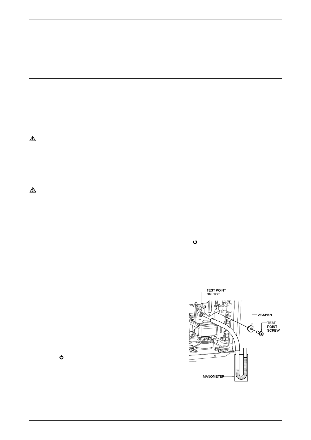
6. Locate the burner pressure test point on the main burner
manifold
Remove the test point screw and washer from the test
point orifice.
Connect the manometer.
7. Switch on the electrical supply at the power outlet to the water
heater and turn on a controller, if one is fitted, by pressing the
on / off ( ) button.
8. The priority light and the on / off operating light will both glow.
9. Open the gas isolation valve fully at the gas inlet to the water
heater, if not already open.

2
Minimum Test Point Gas Pressure
10. Refer to the rating label on the water heater for the minimum test point gas pressure.
11. Open a hot tap slowly until the burners ignite.
12. Press and hold down the MIN button and observe the reading on
the manometer.
“1L” is shown on the LED display.
13. Release the MIN button.
14. If the manometer reading observed in step 12 agrees with the
rating label, no further adjustment is required.
15. To adjust, press and hold down the adjuster button.
“LH” is shown on the controller display.
Note: The adjuster button must be held down continuously through steps 15 to
17.
16. Press and hold down the MIN button and observe the reading on the
manometer.
The manometer reading will change as the test point gas pressure adjusts.
Note: While the MIN button is pressed, the gas pressure will at first increase
then decrease, cycling between an upper gas pressure limit (59 on the LED
display) and a lower gas pressure limit (01 on the LED display).
17. Release the MIN button when the reading on the manometer agrees with the
rating label.
18. Release the adjuster button.
Notes:
•If the burners extinguish and an error code 11 or 12 starts to flash on the LED display:
release the MIN and adjuster buttons
close the hot tap
clear the error code (refer to Owner’s Guide and Installation Instructions supplied with the water
heater)
recommence the procedure from Step 11.
•If the adjuster button is released before Step 17, clear any error code (if displayed) and recommence the
procedure from Step 11.

3
Maximum Test Point Gas Pressure
19. Refer to the rating label on the water heater for the maximum test point gas pressure.
20. To check and adjust the maximum test point gas pressure, follow steps 11 to 18 of the “Minimum Test
Point Gas Pressure” procedure, but;
open the hot tap fully (it may be necessary to open two or three hot taps fully, depending upon the
incoming cold water temperature), and
use the MAX button instead of the MIN button.
Notes:
In Step 15, “6H” will be shown on the LED display.
In Step 16 while the MAX button is pressed, the gas pressure will at first
increase then decrease, cycling between an upper gas pressure limit (39
on the LED display) and a lower gas pressure limit (01 on the LED
display).
21. After setting the minimum and maximum test point gas pressures:
Close the hot tap
Remove the manometer and refit and tighten the test point screw and washer.
22. Open a hot tap again so the burners ignite and test for gas leaks.
23. Close the hot tap and turn off the controller, if one is fitted, by pressing the on/off () button.
24. Switch off the electrical supply at the power outlet to the water heater.
25. Refit the front cover, re-installing the 4 x screws, ensuring that the star-washer and screw are re-inserted
into the same hole as originally installed at the factory (the star-washer ensures earthing of the front cover
panel). Do not tighten the upper two screws at this stage.
Fit one of the cover strips to the bottom of the front cover by inserting the two posts into the two
recesses and gently pushing into position.
Do not fit a cover strip to the top of the front cover as the Flue Terminal Diverter makes it obsolete.

4
DIVERTER INSTALLATION
Note: The Flue Terminal Diverter or Extended Flue Terminal Diverter packed in the carton is factory assembled
with a metal heat shield. The heat shield forms an integral part of the flue diverter and MUST NOT be detached.
DO NOT install the flue terminal if any of the components are missing.
1. Remove all packaging from the Flue Terminal Diverter or Extended Flue Terminal Diverter.
2. The Flue Terminal Diverter or Extended Flue Terminal Diverter (1), 4 x stainless steel mounting brackets
(2A, 2B), (3), (4) and screws (5) are required to be attached to the water heater. The wall mounting bracket
short (7) or long (8) and screws (9), (10) and washers (11) are used with the Extended Flue Terminal
Diverter and are required to be attached to the wall and flue diverter. Refer to the diagrams, “Flue Terminal
Diverter Details” and “Extended Flue Terminal Diverter Details”.
Familiarise yourself with the placement of each bracket in relation to the Diverter and the Rheem
continuous flow water heater front panel before attempting the installation.
Note: The Flue Terminal Diverter or Extended Flue Terminal Diverter can be orientated in either direction.
The Flue Terminal Diverter Details diagram illustrates the left hand flue outlet installation, and the
Extended Flue Terminal Diverter Details diagram illustrates the right hand flue outlet installation.
Flue Terminal Diverter Details Upper Bracket Details
5
6
5
5
2B
2A
5
4
1
3
UPPER BRACKET (2B)
UPPER BRACKET (2A)

5
Extended Flue Terminal Diverter Details
3. Determine the correct flue terminal discharge direction, typically away from the doors and windows of the
dwelling or away from balcony areas of the property. The water heater must be located to ensure that the
location of the flue terminal discharge complies with the requirements of AS 5601 or AS/NZS 5601.1, as
applicable under local regulations. The Diverter (1) outlet grill must not be obstructed by a building
structure or fixture.
4. Remove the 2 x upper front cover screws (6) from the water heater front panel.
5. Attach the shorter upper bracket (2A) to the upper right hand side of the water heater, re-using one of the
screws (6). Ensure the front panel screw (6) is tightened. Note the orientation of the bracket in the detail
drawing ‘Upper Bracket (2A)’ of the “Upper Bracket Details” diagram. The shorter upper bracket is always
installed on the right hand side of the water heater (when facing the unit).
6. Attach the longer upper bracket (2B) to the upper left hand side of the water heater, re-using one of the
screws (6). Ensure the front panel screw (6) is tightened. Note the orientation of the bracket in the detail
drawing ‘Upper Bracket (2B)’ of the “Upper Bracket Details” diagram. The longer upper bracket is always
installed on the left hand side of the water heater (when facing the unit).
7. Position the Diverter over the water heater flue outlet, lining up the recesses in the top surface of the
Diverter with the upper brackets (2A, 2B). Fasten the upper brackets to the top of the Diverter using two
screws (5) per bracket. Tighten the screws.
5
6
3
5
5
1
11
7
10
8
4
9
2B
2A
5

Issue Date: 2017 August 122629 Rev B
6
8. Position the remaining brackets (3) and (4) around the edge of the water heater front panel perimeter and
align to the recesses and mounting holes in the bottom surfaces of the Diverter.
Note: bracket (4) – the longer of the two brackets, is always installed on the left hand side of the water
heater (when facing the unit).
9. Fasten brackets (3) and (4) to the underside of the Diverter using two screws (5) per bracket. Tighten the
screws.
The Diverter assembly should now be firmly mounted over the water heater flue terminal if installed
correctly.
Steps 10 to 12 apply to the installation of the Extended Flue Terminal Diverter.
10. Remove the M4 x 12 mm screw (9) from the top of the Extended Flue Terminal Diverter and position either
the wall mounting bracket short (7) or long (8) to the Diverter’s (1) top surface. Loosely fasten the wall
mounting bracket to the Diverter, reusing the M4 x 12 mm screw (9).
Note: If the water heater is installed in a recess box, the short wall mounting bracket (7) should be used
for the installation. If the water heater is mounted on a wall, the long wall mounting bracket (8) should be
used for the installation.
11. Mark the wall bracket mounting hole positions on the wall. Secure the wall mounting bracket using two
fasteners. Use the two mounting screws (10) and washers (11) with suitable plugs, only if they are suitable
for the wall type. Otherwise select and use alternative fasteners suitable for the application.
Note: Refer to the fastener manufacturer’s information and recommendations for the type of fastener to
use for the wall type and load bearing requirements.
12. Tighten the M4 x 12 mm screw (9) to secure the wall bracket to the Diverter.
13. Check that all screws have been firmly tightened – DO NOT over-tighten as the screw thread can be easily
stripped.
COMMISSIONING
1. Switch on the water heater at the power point and allow the unit to stabilise for 1 minute before testing
its operation.
2. Open a hot tap to ensure the water heater is operating correctly. Check the LED display on the front panel
to identify any error codes, should the unit not operate correctly.
3. Should the water heater display an error code, switch off the power and wait 5 minutes before restarting.
Once restarted, allow the water heater to stabilise for 1 minute before retesting.
4. If the water heater continues to display an error code, note the error code and contact Rheem Service
on 131031.
This manual suits for next models
3
Table of contents
Other Rheem Heater manuals
Popular Heater manuals by other brands

Pentair
Pentair MASTERTEMP 125 Installation and user manual

Havener
Havener WHE 170 operating instructions

Intuis
Intuis TACTIC WIFI manual

Haverland
Haverland ECOVIEW Instruction & installation manual

STIEBEL ELTRON
STIEBEL ELTRON CBS 20 S Operating and installation instructions

Scarlett
Scarlett Comfort SC-FH53K03 instruction manual