Installation Instructions for Wi-Q Technology™ EXQ Exit Hardware Trim
2BEST
a Product Group of dormakaba USA Inc.
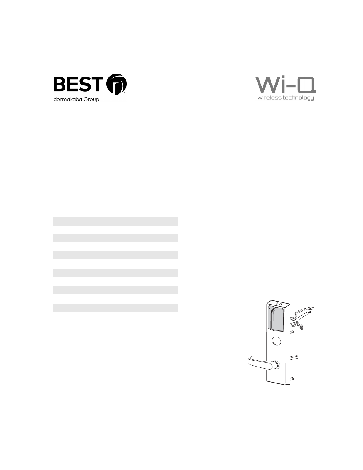
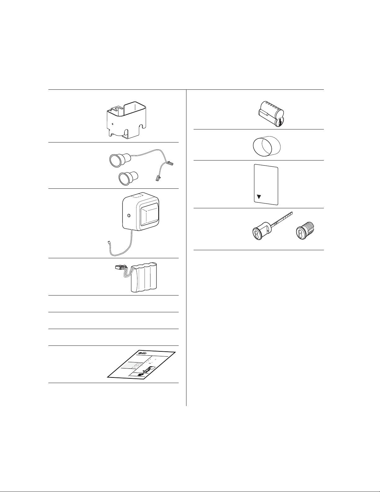
❑Battery bracket
❑Door position
switch with
magnet
❑Battery cover with
antenna
❑Battery pack
❑Battery cover screw
package
❑Bar code ID sticker
(for your records)
❑Cable ties, butt-
splices, and tape
❑Installation
templates and
instructions
BESTACCESS SYSTEMS
a
a Product Group of dormakaba USA Inc.
1
Introduction
Theseinstallation instructions describe how to install your
BEST®Wi-Q Technology™ EXQ Series Exit Hardware Trim.
ElectronicStand-Alone Exit Hardware Trim is available for
usewith the following types of wide stile exit devices
manufacturedby Stanley-Precision Hardware (2000
Series)and Von Duprin® (98/99 Serie s):
Notall features are available for all ex it device configura-
tions.The table below details what sensors are available
forwhich exit device configurations:
n
Contents
Theseinstructions cover the following topics:
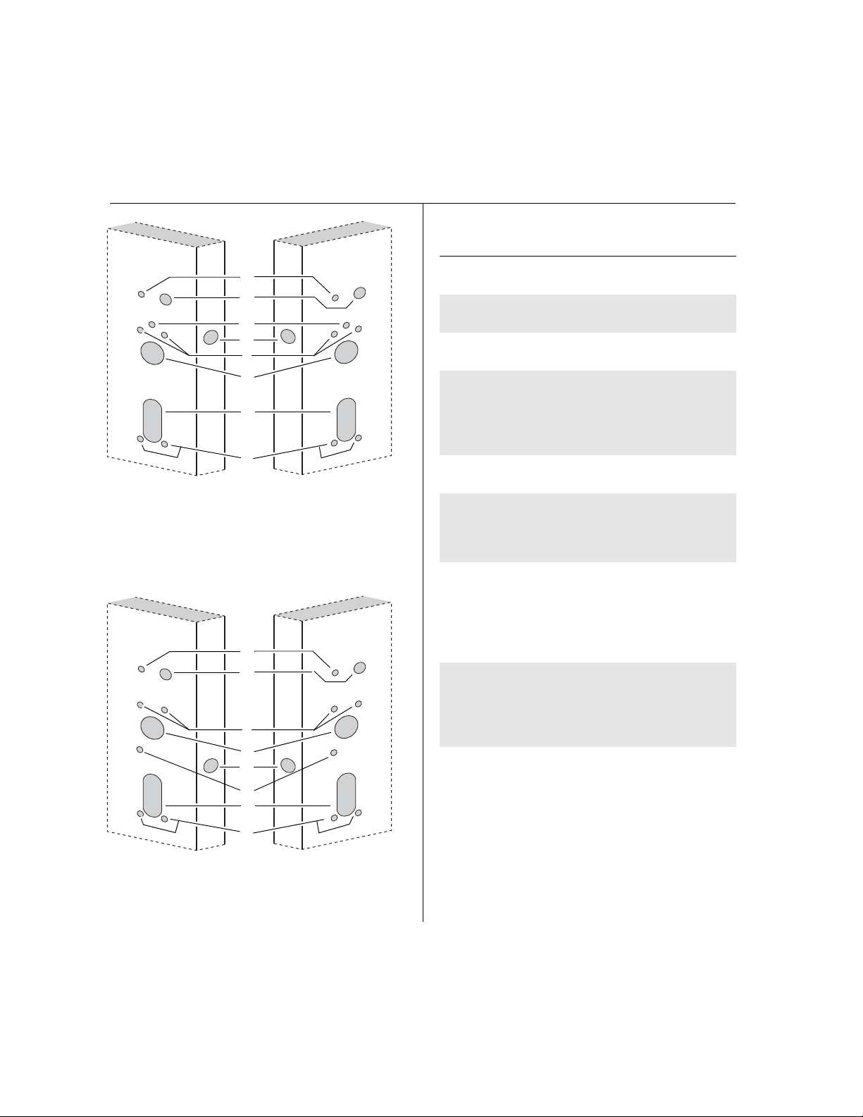
Planningthe installation ................................................1
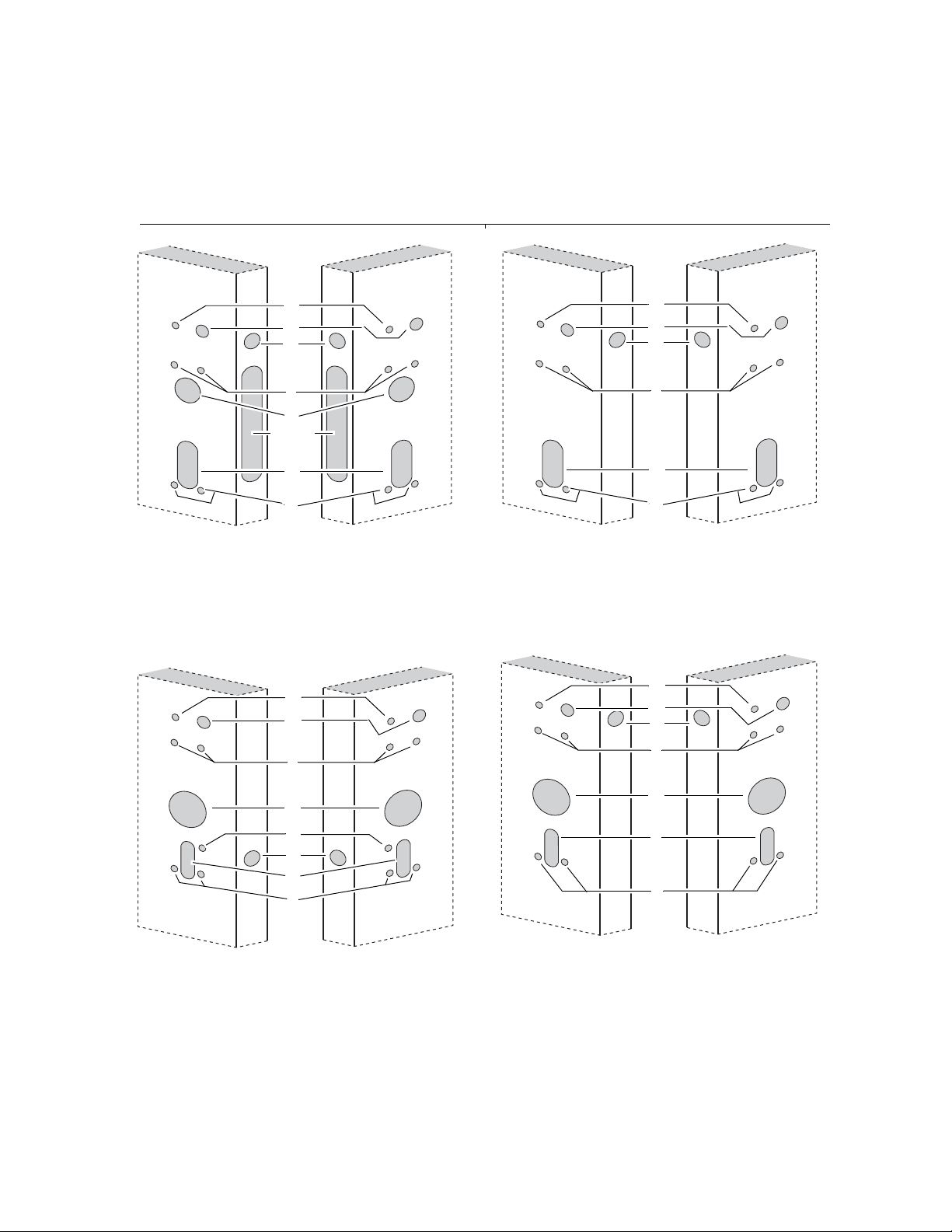
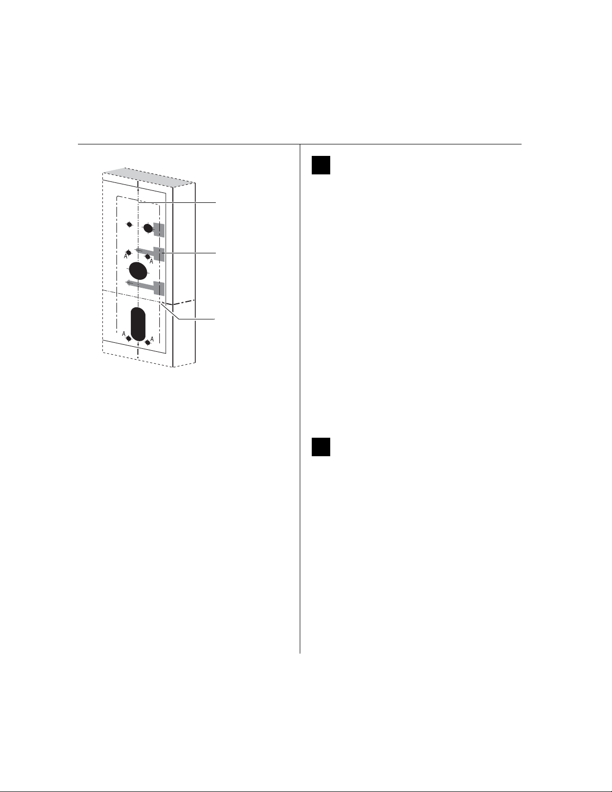
Preparingthe door .......................................................... 4
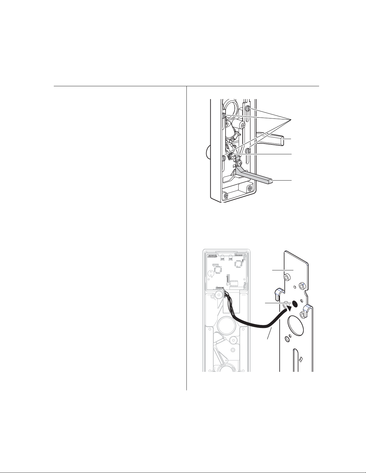
Installingthe exit hardware and trim............................ 8
Completingthe installation..........................................15
Device DS
a
a. Doorpositionsens ing
TS
b
b. Request-to-exit(PHI touchbar monitoring)
LS
c
c. Latchsensing
Precision
Rim(2100)
SurfaceVertical (2200)
Mortise(2300)
WoodDoor Concealed (2700)
ConcealedVertical (2800)
VonDuprin
Rim
SurfaceVertical
ConcealedVertical
Site survey
Usethe followin g survey to record information about the
installationsite and hardware application.
Exithardware type:
Doorhanding and bevel:
Left-handreverse bevel (LHRB)
Right-handreverse bevel (RHRB)
Doortype:
Doorthickness: inches(1-3/4″to 2-1/4″ )
Components checklist
Usethe following checklist to make sure that you have the
itemsnecessary to install your EXQ Exit Hardware Trim.
rim surface vertical rod
mortise concealedvertical rod
Wood Metal
Escutcheonand
leverassembly
Batterybracket
Installation Instructions for
Wi-Q Technology™EXQ
Exit Hardware Trim
Tools required
Use the following checklist to make sure that you have the
tools necessary to install your EXQ Exit Hardware Trim.
For Precision® Hardware and Sargent installations
❑1-3/8” dia hole saw (EV function only)
❑1-1/8” dia hole saw
For Von Duprin® installations
❑2” dia hole saw
❑3/4” dia hole saw
For BEST® cylinders
❑BEST ED211 cylinder wrench
For surface vertical exit devices
❑Razor blade
❑7-pin core (only
included if ordered
with trim)
❑Cylinder mounting
sleeve (for Von
Duprin functions
only)
❑Temporary
operator card
❑Key cylinder and
keys (only included
if ordered with
trim).
❑Electric drill (preferably corded) ❑Straight edge
❑Jigsaw ❑Square
❑Wire snips ❑Pencil/marker
❑Wire strippers ❑7/16” dia drill bit
❑Phillips screwdriver ❑7/8” dia drill bit
❑Measuring tape ❑1” dia hole saw
BEST
Temporary
Operator
Rim cylinder Mortise cylinder
OR