Best 40H Series User manual

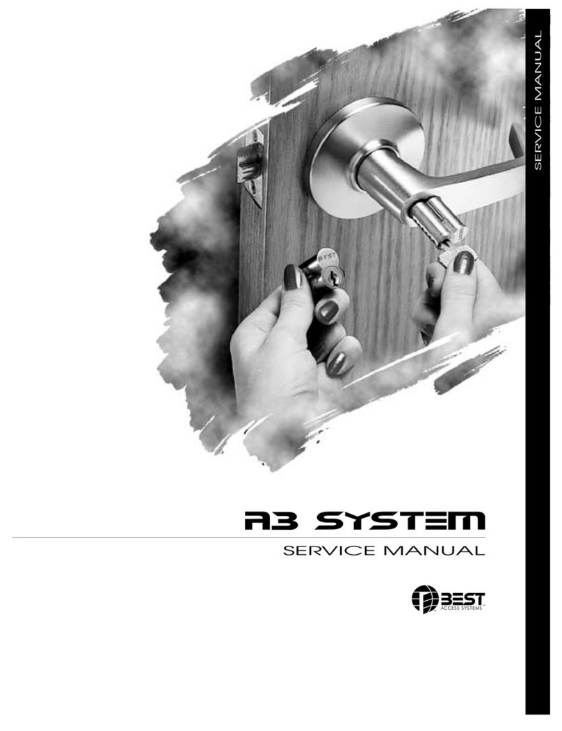
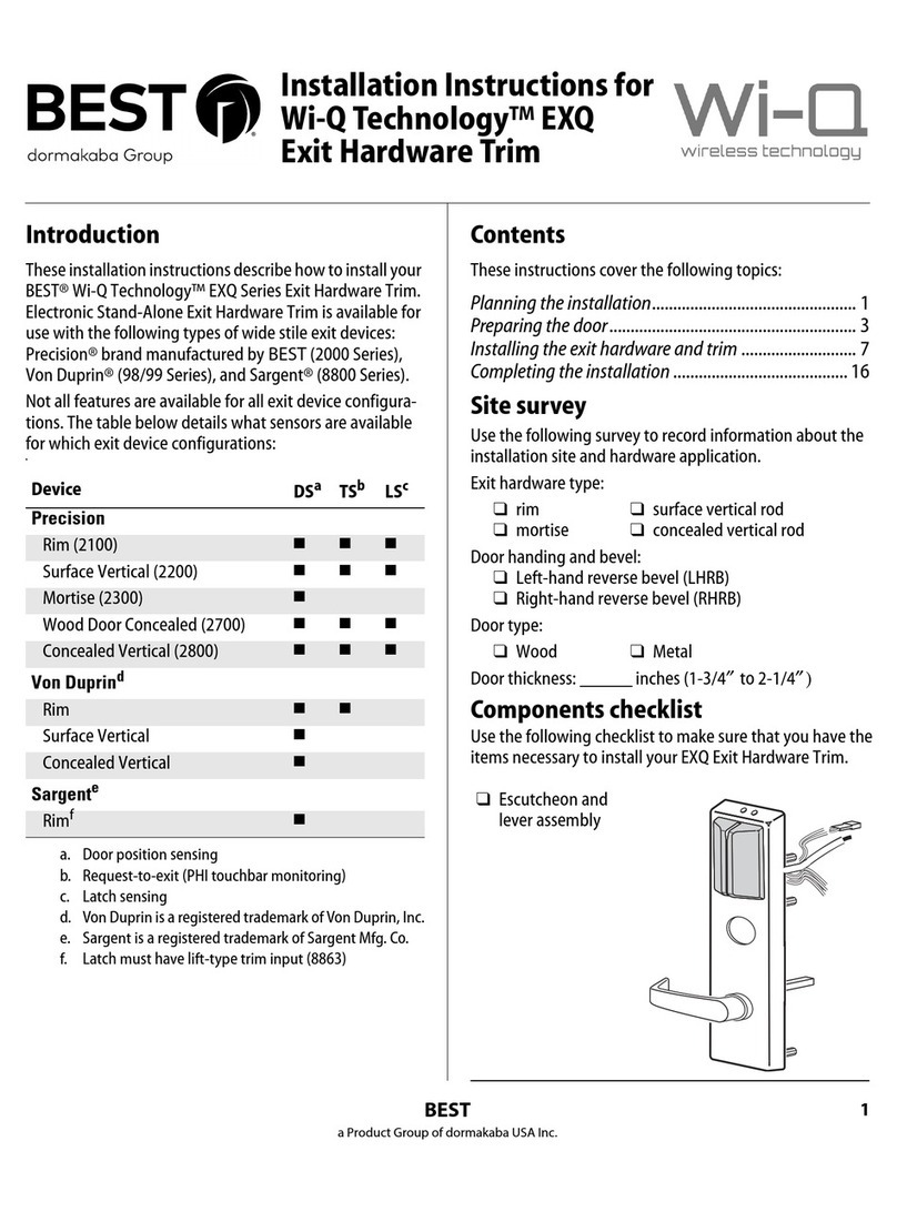
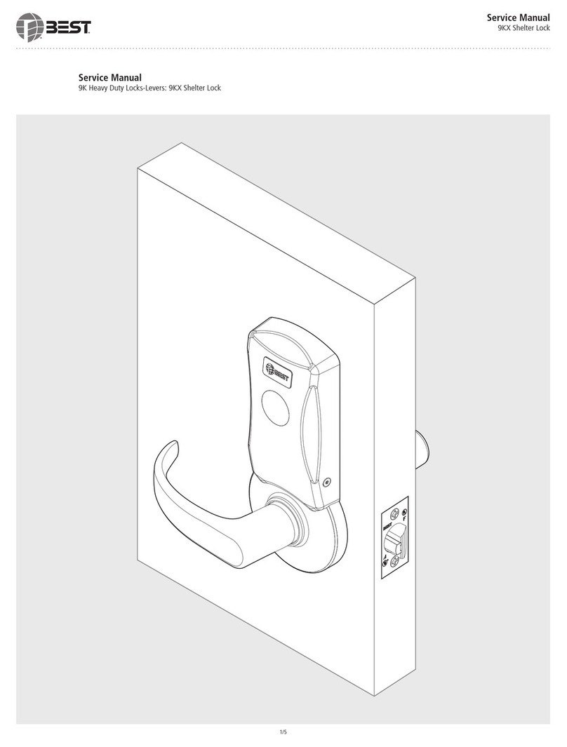
40H SERIES
SERVICE MAN U A L
HEAVY DUTY MORTISE LOCKS

CREDITS/COPYRIGHT
Copyright ©2021 dormakaba USA Inc. All rights reserved.
Information in this document is subject to change without notice and does not
represent a commitment on the part of dormakaba USA Inc. The software
described in this document are furnished under a license agreement or
nondisclosure agreement.
This publication is intended to be an accurate description and set of instructions
pertaining to its subject matter. However, as with any publication of this complexity,
errors or omissions are possible. Please call dormakaba USA Inc. at
1-800-392-5209 if you see any errors or have any questions. No part of this
manual and/or databases may be reproduced or transmitted in any form or by
any means, electronic or mechanical, including photocopying, recording, or
information storage and retrieval systems, for any purpose, without the express
written permission of dormakaba USA Inc.
This document is distributed as is, without warranty of any kind, either express or
implied, respecting the contents of this book, including but not limited to implied
warranties for the publication’s quality, performance, merchantability, or fitness
for any particular purpose. Neither dormakaba USA Inc., nor its dealers or
distributors shall be liable to the user or any other person or entity with respect to
any liability, loss, or damage caused or alleged to be caused directly or indirectly by
this publication.
Life Safety Code is a registered trademark of the National Fire Protection
Association.
Written and designed at
dormakaba Americas Headquarters
6161 East 75th Street
Indianapolis, IN 46250
T81602 Rev C 1922545 ER-7991-6 August 2021

40H Series Service Manual iii
CONTENTS
FIGURES 1–IX
GETTING STARTED 1–1
Introduction 1–1
Certifications and standards 1–1
45H & 47H overview 1–2
Lock characteristics 1–2
Lock dimensions 1–2
45HW & 47HW overview 1–4
Lock characteristics 1–4
Lock dimensions 1–4
48H & 49H overview 1–6
Lock characteristics 1–6
Lock dimensions 1–6
Documentation package 1–8
Technical support 1–8
Support services 1–8
Telephone technical support 1–8

CONTENTS
iv 40H Series Service Manual
INTRODUCING THE 40H LOCK 2–1
Overview 2–1
Ways to order 2–1
Function-specific locks 2–1
Universal locks 2–2
Three-part locks 2–2
The advantage of kits 2–2
Working with universal functions 2–2
Working with trim kits 2–3
Trim one side locks 2–5
LOCK FUNCTIONS 3–1
45H & 47H Functions by ANSI designation & lock function quick reference 3–2
45HW & 47HW lock function quick reference 3–3
Function descriptions 3–4
Single-keyed functions 3–5
Double-keyed functions 3–8
Deadlocked functions 3–10
Non-keyed functions 3–11
Special functions 3–13
Electrified functions 3–14
MORTISE CASE PARTS 4–1
A function case—office lock 4–2
AB function case—office lock 4–14
AD function case—deadlock 4–34
AT function case—office lock 4–4
B function case—entrance lock 4–16
B5 function case—entrance lock 4–22
B7 Function case—entrance lock 4–22
BA function case—entrance lock 4–18
BW function case—entrance lock 4–20
C function case—public entrance lock 4–4
CHB function case—holdback lock 4–12
D function case—storeroom lock 4–4
DEL function case—Electrically locked fail safe lock 4–38
DEU function case—Electrically unlocked fail secure 4–40
G function case—communicating lock 4–22
H function case—hotel lock 4–24
HJ function case—hotel lock 4–24
IND function case—intruder lock 4–26

CONTENTS
INL function case—intruder lock 4–4
L function case—privacy lock 4–28
LB function case—privacy lock 4–30
LEL function case—Electrically locked fail safe lock 4–58
LEU function case—Electrically unlocked fail secure 4–60
LT function case—privacy lock 4–6
N function case—passage lock 4–8
NX function case—exit lock 4–10
NXEL function case—electrically locked fail safe lock 4–46
NXEU function case—electrically unlocked fail secure lock 4–48
R function case—classroom lock 4–4
RD function case—classroom deadlock 4–36
RHB function case—classroom holdback lock 4–12
S function case—storeroom lock 4–18
T function case—dormitory lock 4–26
TA function case—dormitory lock 4–32
TD function case—dormitory lock 4–24
TDEL function case—Electrically locked fail saf
elock 4–50
TDEU function case—Electrically unlocked fail secure 4–52
TWEL function case—Electrically locked fail safe lock 4–54
TWEU function case—Electrically unlocked fail secure 4–56
W function case—storeroom lock 4–4
WD function case—deadlock 4–34
WEL function case—Electrically unlocked fail safe 4–42
WEU function case—Electrically unlocked fail secure 4–44
XR function case—classroom lock 4–4
YD function case—deadlock 4–34
ZD function case—storeroom lock 4–4
Case only locks 4–62
How to order standard mortise locks 4–62
How to order electrified mortis e locks 4–63
Case only components 4–64
TRIM PARTS 5–1
Outside trim kits 5–2
How to order 5–2
Kit components 5–3
Inside trim kits 5–6
How to order 5–6
Kit components 5–7
40H Series Service Manual v

CONTENTS
Strike packages 5–10
How to order5–10
Strike packages 5–11
Lever sets 5–12
How to order
Lever sets 5–13
5–12
Faceplate kits 5–15
How to order5–15
Faceplate kits5–15
Replacement spindles 5–16
How to order5–16
Replacement spindles 5–17
Screw kits 5–18
How to order5–18
Screw kits 5–19
Cylinders and cams5–20
How to order5–20
Cylinders by door thickness 5–21
Cylinder ring lengths 5–21
Escutcheon assemblies 5–23
J trim outside escutcheons 5–23
J trim inside escutcheons 5–24
M & N trim outside escutcheons 5–25
M & N trim inside escutcheons 5–26
Roses and rose rings 5–27
Dummy trim 5–27
Visual indicator trim 5–28
Service equipment 5–29
Driver bits 5–30
Accessories for electrified locks 5–31
SERVICE AND MAINTENANCE 6–1
Changing th e hand 6–2
Changing hand quick reference 6–2
Changing handing for the mortise case 6–2
To rotate the latchbolt: 6–2
To change the position of the hub toggles: 6–3
Changing the function for universal cases 6–5
Changing the function for UNR cases 6–5
To adjust the shuttle screw positions: 6–5
To change the position of the hub toggles: 6–6
Changing the function for UNAB cases 6–6
Changing the function for UNT cases 6–6
Troubleshooting 6–7
vi 40H Series Service Manual

CONTENTS
48H & 49H LOCKS 7–1
Function quick reference 7–1
Function descriptions 7–2
48H & 49H Mortise cas
eparts 7–2
K function case—cylinder deadlock 7–3
L function case—cylinder deadlock 7–3
M function case—cylinder deadlock 7–3
R function case—classroom deadlock 7–4
48H Trim parts 7–5
49H High security deadbolt trim parts
Strikes and strike boxes 7–7
Troubleshooting 7–8
7–6
GLOSSARY A–1
INSTALLATION INSTRUCTIONS B–1
INDEX C–1
40H Series Service Manual vii

CONTENTS
viii 40H Series Service Manual

40H Series Service Manual ix
FIGURES
GETTING STARTED
45H & 47H mortise case and strike dimensions 1–3
45HW & 47HW mortise case and strike dimensions 1–5
48H & 49H mortise case and strike dimensions 1–7
LOCK FUNCTIONS
Understanding function drawings 3–4
MORTISE CASE PARTS
A function case exploded diagram 4–2
AT, C, D, INL, R, W, ZD, XR function case exploded diagram 4–4
LT function case exploded diagram 4–6
N function case exploded diagram 4–8
NX function case exploded diagram 4–10
CHB, RHB function case exploded diagram 4–12
AB function case exploded diagram 4–14
B function case exploded diagram 4–16
BA, S function case exploded diagram 4–18
BW function case exploded diagram 4–20
G, B5, B7 function case exploded diagram 4–22
H, HJ, TD function case exploded diagram 4–24
IND, T function case exploded diagram 4–26
L function case exploded diagram 4–28
LB function case exploded diagram 4–30
TA function case exploded diagram 4–32
AD, WD, YD function case exploded diagram 4–34

Figures
x40H Series Service Manual
RD function case exploded diagram 4–36
DEL function case exploded diagram 4–38
DEU function case exploded diagram 4–40
WEL function case exploded diagram 4–42
WEU function case exploded diagram 4–44
NXEL function case exploded diagram 4–46
NXEU function case exploded diagram 4–48
TDEL function case exploded diagram 4–50
TDEU function case exploded diagram 4–52
TWEL function case exploded diagram 4–54
TWEU function case exploded diagram 4–56
LEL function case exploded diagram 4–58
LEU function case exploded diagram 4–60
Case only lock – faceplate and case for AB function shown 4–64
TRIM PARTS
OS1 – Outside lever only 5–4
OS2 – Outside lever & cylinder 5–4
OS3 – Outside lever & access plate 5–5
OS4 – Outside cylinder only 5–5
IS1 – Inside lever only 5–8
IS2 – Inside lever & thumb turn 5–8
5–8IS3 – Inside lever & cylinder
IS4 – Inside cylinder only 5–9
IS5 – Inside thumb turn only 5–9
Lip to center dimension 5–10
Strike kit 1– Universal strike package 5–11
Strike kit 4– Strike box only 5–11
Strike kit 1– Universal strike package with flat-lipped option 5–11
Strike kit 5– Magnetic strike box only 5–11
Solid tube / return (style 3) 5–14
Knob (style 4) 5–14
Curved return (style 14) 5–14
Contour/angle return (style 15) 5–14
Curve / no return (style 16) 5–14
Faceplate kits 5–15
Spindle kit 2 – Standard replacement spindle 5–17
Spindle kit 4 – Hook replacement spindle 5–17
Screw kit components 5–19

Figures
40H Series Service Manual xi
Cylinders 5–21
Cylinder rings 5–22
Cylinder cams 5–22
Outside J trim escutcheons 5–23
Inside J trim escutcheons 5–24
Outside M & N trim escutcheons 5–25
Inside M & N trim escutcheons 5–26
Roses & rose rings 5–27
Dummy trim parts 5–27
Keyed visual indicator trim 5–28
Privacy visual indicator trim 5–28
Service equipment 5–29
Driver bits 5–30
Accessories for electrified locks 5–31
SERVICE AND MAINTENANCE
Explanation of the hand and bevel of the door 6–2
Rotating the latchbolt 6–3
Positioning the hub toggles 6–4
Positioning the shuttle screws and stop screw 6–6
48H & 49H LOCKS
Understanding function drawings 7–2
K, L, M function case 7–3
R function case 7–4
Deadbolt trim 7–5
High security deadbolt trim 7–6
Strikes and strike box 7–7

Figures
xii 40H Series Service Manual

40H Series Service Manual 1–1
1GETTING STARTED
INTRODUCTION
The
40H
Series Service Manual
contains essential
information to help you maintain your 40H Series
Locks.
CERTIFICATIONS AND STANDARDS
■The 40H Series Locks are listed by Underwriters
Laboratories (U.S. and Canada) for use on 3 hr.,
Alabeldoors.
■The 40H Series Locks with deadbolt are certified
by Miami-Dade County Code Compliance Office
for use in applications requiring a design
pressure rating of ± 100 PSF for single doors
and ± 50 PSF for double door openings.
■The 40H Series Locks without deadbolt are
certified by Miami-Dade County Code
Compliance Office for use in applications
requiring a design pressure rating of ± 60 PSF
for single doors and ± 35 PSF for double door
openings.
■The 45HW and 47HW Locks are UL listed for
GYQS electrically controlled single point locks or
latches.
■The 45HW and 47HW Locks are approved by the
California State Fire Marshall (CSFM) pursuant
to section 13144.1 of the California Health and
Safety Board.

Getting Started
1–2 40H Series Service Manual
■The 45HW and 47HW locks are approved by the city of New York
Board of Standards and Appeals under calendar number 49-88-SA.
See CSFM listing number 4136-1175:101.
■45H Locks meet or exceed ANSI A156.13, Series 1000, Grade 1
Operational and Grade 2 Security standards, when used with the 1CD
core.
■47H Locks meet or exceed ANSI A156.13, Series 1000, Grade 1
Operational and Grade 1 Security standards.
■47H Locks conform to UL437 Standard for Key Locks, referencing
Door Locks.
■49H Locks conform to ANSI 156.5, Grade 1 standards.
■The 1E7J4 cylinder used in 47H Locks conforms to UL437 Standard
for Key Locks, referencing High Security Cylinders, and is listed for
Canada as well as the United States.
■The lock case and faceplate dimensions fit the standard door
preparation as specified in ANSI A115.1.
■The strike fits the standard door frame cutout as specified in
ANSI A115.1.
■Lever styles 3, 14 and 15 conform to California Administrative Code
Title 19 and Title 24.
45H & 47H OVERVIEW
Lock
characteristics
All 45H & 47H Mortise Locks have the following characteristics:
Lock
dimensions
The following diagram shows the dimensions for the 45H & 47H
mortise case and strike.
Feature Dimensions
Case size
Backset
Door thickness range
5 7/8″ × 4 1/4″ × 1″
2 3/4″
1 3/4″ standard–up to 5″ †
†. All mortise functions, except trim one side only functions,
can be installed on 5″ thick doors if the mortise is centered
in the door. Trim one-side-only functions can be installed on
doors up to 2 1/2″ thick if the mortise is centered in the door.

Getting Started
1–3
Figure 1.1 45H & 47H mortise case and strike dimensions
40H Series Service Manual
3/32 in
(2.4 mm)
Strike plate —
overhead view
1 7/32 in
(31.0 mm)
31/32 in (24.6 mm)
3/64 in
(1.2 mm)
1 1/32 in
(26.2 mm)
Strike box —
overhead view
3 3/64 in
(77.4 mm)
3 3/8in
(85.7 mm)
1 1/4in
(31.8 mm)
3 21/64 in
(84.5 mm)
4 7/8in
(123.8 mm)
4 1/8in
(104.8 mm)
11/16 in
(17.5 mm)
Centerline
of lock
Centerline
of strike
40HS1
Strike plate
2 x #12–24 screw
Note 5
3/8in
(9.5 mm)
Strike box
15/16 in
(23.8 mm)
1 7/32 in
(31.0 mm)
4 25/32 in
(121.4 mm)
1 1/8in
(28.6 mm)
1 in (25.4 mm)
4 in
(101.6 mm)
9/16 in
(14.3 mm)
11/32 in
(8.7 mm)
5/8in
(15.9 mm)
8 in
(203.2 mm)
7 1/4in
(184.2 mm)
1 1/4in
(31.8 mm)
Faceplate
2 x #12-24 screw
7/32 in
(5.6 mm)
3 5/8 in
(92.1 mm) 1 3/16 in
(30.2 mm)
1 7/8 in
(47.6 mm)
3/4in
(19.1 mm)
11/2 in
(38.1 mm)
Centerline
of lever to
centerline
of lock
1 11/16 in
(42.9 mm)
7/32 in (5.6 mm)
13/16 in (20.6 mm)
2 27/64 in
(61.5 mm)
3 5/8 in
(92.1 mm)
5 7/8 in
(149.2 mm)
45 degrees
Clear for screws
1/16 in (1.6 mm) deep
2 3/4 in (69.9 mm)
backset
1 in
(25.4 mm)
1/8 in
(3.2 mm)
4 1/4 in
(108.0 mm)
Mortise case — overhead view
Adjusts 90 degrees ± 3 ½ degrees
7/8 in (22.2 mm)
Mortise case — side view

Getting Started
1–4 40H Series Service Manual
45HW & 47HW OVERVIEW
Lock
characteristics
All 45HW & 47HW Mortise Locks have the following characteristics:
Lock
dimensions
The following diagram shows the dimensions for the 45HW & 47HW
mortise case and strike.
Feature Dimensions
Case size
Backset
Door thickness range
5 7/8″ × 4 1/4″ × 1″
2 3/4″
1 3/4″ standard–up to 5″ †
†. All mortise functions, except trim one side only functions,
can be installed on 5″ thick doors if the mortise is centered
in the door. Trim one-side-only functions can be installed on
doors up to 2 1/2″ thick if the mortise is centered in the door.

Getting Started
1–5
Figure 1.2 45HW & 47HW mortise case and strike dimensions
40H Series Service Manual
3/32 in
(2.4 mm)
Strike plate —
overhead view
1 7/32 in
(31.0 mm)
31/32 in (24.6 mm)
3/64 in
(1.2 mm)
1 1/32 in
(26.2 mm)
Strike box —
overhead view
3 3/64 in
(77.4 mm)
3 3/8in
(85.7 mm)
1 1/4in
(31.8 mm)
3 21/64 in
(84.5 mm)
4 7/8in
(123.8 mm)
4 1/8in
(104.8 mm)
11/16 in
(17.5 mm)
Centerline
of lock
Centerline
of strike
40HS1
Strike plate
2 x #12–24 screw
3/8in
(9.5 mm)
Strike box
15/16 in
(23.8 mm)
1 7/32 in
(31.0 mm)
1 1/8in
(28.6 mm)
1 in (25.4 mm)
4 in
(101.6 mm)
9/16 in
(14.3 mm)
11/32 in
(8.7 mm)
5/8in
(15.9 mm)
8 in
(203.2 mm)
7 1/4in
(184.2 mm)
1 1/4in
(31.8 mm)
Faceplate
2 x #12-24 screw
7/32 in
(5.6 mm)
3 5/8 in
(92.1 mm)
1 in (25.4 mm)
min. clearance
for wires
1 3/16 in
(30.2 mm)
1 7/8 in
(47.6 mm)
3/4in
(19.1 mm)
11/2 in
(38.1 mm)
Centerline
of lever to
centerline
of lock
1 11/16 in
(42.9 mm)
7/32 in (5.6 mm)
13/16 in (20.6 mm)
2 27/64 in
(61.5 mm)
3 5/8 in
(92.1 mm)
5 7/8 in
(149.2 mm)
45 degrees
Clear for screws
1/16 in (1.6 mm) deep
3/8 in (9.5 mm)
clearance for wires
4 25/32 in
(121.4 mm)
2 3/4 in (69.9 mm)
backset
1 in
(25.4 mm)
1/8 in
(3.2 mm)
4 1/4 in
(108.0 mm)
Mortise case — overhead view
Adjusts 90 degrees ± 3 ½ degrees
7/8 in (22.2 mm)
C
F
G
H
G
Mortise case — side view

Getting Started
1–6 40H Series Service Manual
48H & 49H OVERVIEW
Lock
characteristics
All 48H & 49H Mortise Locks have the following characteristics:
Lock
dimensions
The following diagram shows the dimensions of the 48H & 49H mortise
case and strike.
Feature Dimensions
Case size
Backset
Door thickness range
4 3/16″ × 3 5/8″ × 1″
2 3/4″
1 3/4″ standard–up to 5″ †
†. All mortise functions, except R and trim one side only
functions, can be installed on 5″ thick doors if the mortise is
centered in the door.

Getting Started
40H Series Service Manual 1–7
Figure 1.3 48H & 49H mortise case and strike dimensions
31/32 in
Centerline
1 1
/32 in
1 7
/32 in
3
/64 in
3
/32 in
2 1
/2in
3 1
/2in
1 1
/2in
11/16 in
3
/32 in
1 1
/8in
1 7
/8in
1 1
/4in
5
/8in
3 3
/16 in
4
7
/8in
3 3
/8in
4 1
/8in
Centerline
11/16 in
6 59/64 in
1 3
/4in Dia.
1 17/32 in Dia.
1 3
/16 in
1 7
/32 in
1 27/32 in
5 3
/8in
2 11/16 in
4 5
/8 in
1 in
4 3
/16 in
2 3
/4in
7
/32 in
4 3
/16 in
1 in
3 3
/8in
3 5
/8in
1 3
/16 in
27/32 in
Strike box —
overhead view
Mortise case —
overhead view
Faceplate
Case
Strike plate —
overhead view
48HS2 Strike plate
48HS1 Strike plate

Getting Started
1–8 40H Series Service Manual
DOCUMENTATION PACKAGE
The following documentation is available to help you with the
installation, start-up, and maintenance of your 40H Series Locks.
The installation and assembly instructions also can be ordered
separately:
The templates required for lock installations also can be ordered
separately:
TECHNICAL SUPPORT
Support
services
Telephone
technical
support
When you have a problem with a 40H Series Lock, your first resource
for help is the
40H
Series Service Manual
. If you cannot find a
satisfactory answer, contact your local dormakaba Representative.
A factory-trained Certified Product Specialist (CPS) is available in your
area whenever you need help. Before you call, however, please make
sure you are where the hardware is located, and that you are prepared
to give the following information:
■what happened and what you were doing when the problem arose
■what you have done so far to fix the problem.
dormakaba USA Inc. representatives provide telephone technical
support for all 40H Series products. You may locate the representative
nearest you by calling (800) 392-5209 Monday through Friday, between
8:00 a.m. and 5:00 p.m. eastern standard time; or visit the web page,
https://dhwsupport.dormakaba.com/hc/en-us.
Document Title Doc. No.
T81162
T81612
T81175
Installation Instructions for 45H & 47H Mortise Locks
Installation Instructions for 45HW & 47HW Electrified
Mortise Locks
Installation Instructions for 48H & 49H Mortise Locks
Installation Instructions for the Mortise Lock Cylinder
T61972
Document Title Doc. No.
T81163
T81166
T81184
T81183
T81611
T61965
H15 Template; Installation Template for
45H & 47H and 45HW & 47HW Mortise Locks
H16 Template; Installation Specifications for
45H & 47H Mortise Locks
H18 Template; Installation Template for
48H & 49H Mortise Locks
H17 Template; Installation Specifications for
48H & 49H Mortise Locks
H19 Template; Installation Specifications for
45HW & 47HW Electrified Mortise Locks
E01 Template for 1E Cylinders
E06 Template for 1E7J4 and 1E7K4 Cylinders
T61970
This manual suits for next models
4
Table of contents
Other Best Lock manuals
Popular Lock manuals by other brands

Ideal Security
Ideal Security Decibel SL5001 quick start guide

Wittkopp
Wittkopp BlueCam greendot operating instructions

Assa Abloy
Assa Abloy eCLIQ Technical manual

Secu
Secu SELO-BR operating instructions

Assa Abloy
Assa Abloy Corbin Russwin FE6700 Series installation instructions

BEA
BEA 10MAGLOCK1UL quick start guide