Bestcare BESTSTAND SA228 User manual
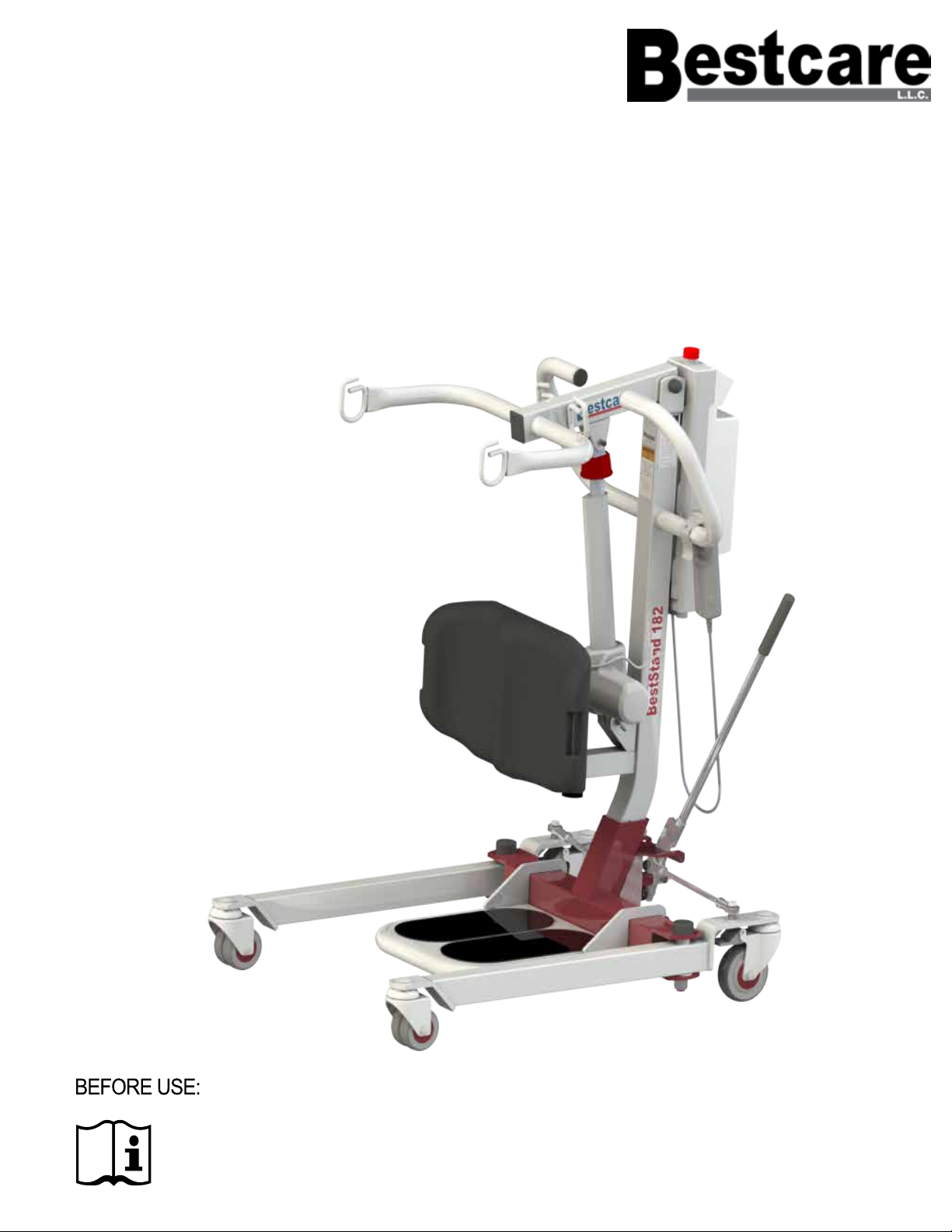
BESTSTAND®
SIT-TO-STAND LIFT
Model: SA228 / SA228H / SA182 / SA182H
Ensure the product has been assembled according to the instructions in this manual.
All operators should read and understand the instructions for safe and proper operation of the
patient lift.

This page was intentally left blank.

Thank you for choosing Bestcare!
To better serve you, please record
the following information for future use:
INSPECT YOUR MERCHANDISE
Upon receipt of your Bestcare Stand, verify that it is complete and free from
any shipping damage. Refuse delivery if the packaging appears to be badly
damaged. If the merchandise is damaged or any component is missing, contact
the shipping company immediately and le a claim. For further assistance,
contact your local dealer or Bestcare LLC.
Supplier Name:
Supplier Telephone:
Product Serial Number:
Date of Purchase:
DEFINITIONS & SYMBOLS
In this manual the user refers to the patient or resident and may be used
interchangeably at different times. Caregiver refers to the operator or person
who is assisting with the transfer.
Warning! Failure to heed this warning may result in damage to the
product or serious injury to the operator and/or user.
Important instructions follow. Read and understand the instructions in
the manual before using the product.
Note! Important information concerning the product and/or its correct
and proper usage follows.
Symbols used in this manual and their meanings:
i
1
Date of Manufacture
The manufacture date can be found on the serial
number. The YY on the serial number is the
manufacture year, and the MM is the manufacture
month.
BestStand SA228
MAX LOAD: 500LB
For service, please contact your
dealer or sales representative.
S/N: SA228YYMM2XXX
®
1-877-822-9033
2920 Pacific Dr,
Norcross, GA 30071
MASS OF LIFT:108LB(49KG)

Safety Instructions
The BestStand Series of full body patient lifts reect innovative state
of the art design to increase user mobility. A BestStand lift will provide
years of service if it is properly maintained as any electric and/or
mechanical equipment requires. Please pay careful attention to the
following important information regarding the care, maintenance, and operation
of the patient lift. Carefully read these instructions before assembling the lift, or
attempting to lift a user with the device.
2
• Special care must be taken with users/patients who cannot
themselves provide assistance while being lifted. (i.e. patients who are
comatose, spastic, agitated, or otherwise severely handicapped.)
• The patient lift should be used solely for transferring a user/patient
from one utility (beds, chairs, toilets, etc.) to another. The patient lift should
not be used for transporting or moving any patient from one location to
another location.
• During lifting or lowering, whenever possible, always keep the base of the lift
in the widest position.
• The base of the lift should be closed before moving the lift.
• Do not roll casters over any object while the user/patient is in the sling.
• Do not lock casters during lifting.
• While being lifted in a sling, always keep the user/patient centered over the
base and facing the caregiver operating the lifter.
• Never leave the user/patient unattended during lifting.
The BestStand assist a person to be lifted and transferred safely, with minimum
physical effort provided by the caregiver. Before attempting to lift anyone,
please practice operating the lift. Also prior to actual lifting, explain the lifting
procedure to the user/patient.
Service personnel may contact Bestcare for any information, instructions or
certain parts for servicing purpose.
i
Please Note
Type B applied parts
Class II Equipment

WARNING!
3
• NO modication of this equipment is allowed. It is unsafe to modify the
equipment from its original state. This product is deemed safe to use with
only the original parts as delivered. Unauthorized use of any modied
equipment may result in serious injury or death.
• DO NOT replace any components of the lift without consulting with
Bestcare, and must follow proper instruction from Bestcare when replacing
any components.
• DO NOT service any parts of the lift while in use with a patient.
• It is NOT safe to load the equipment more than the indicated maximum safe
working load.
• IF any accessories with lower load capacity than the equipment itself is used,
DO NOT load the equipment more than the lowest maximum safe
working load.
• REMOVE the battery if the lift will not be used for some time, to prevent
battery leakage.
• This equipment DOES NOT consist of any materials or ingredients to
which patients are exposed, that may cause bodily harm or injury.
• Prolonged exposure or physical contact with any part of the equipment will
not cause skin irritation, allergic reaction, etc.
• Using accessories, detachable parts, or materials not described in the
instruction manual MAY RESULT IN SERIOUS INJURIES.
• Keep the equipment away from children and pets when in use. IT MAY
CAUSE SERIOUS INJURY OR DEATH.
• Keep the equipment away from pests or pest infested area. Diseases
transferred from pests to the equipment MAY CASUE SERIOUS ILLNESS
to patients upon contact.
• If the lift is left under the sun for long period of time, be CAUTIOUS as the
surface of the lift may be hot.
• There are no risk if the lift is exposed to reasonably foreseeable
environmental conditions
• Caution! The controller contains parts and assemblies that could be
susceptible to damage by electrostatic discharge (ESD). To reduce
the likelihood of this from happening, one should be grounded prior to
operate the controller.
• DO NOT use the lift on a inclined surface that that greater than 5°

4
FEATURES & OVERVIEW
iPrior to assembly, unpack all parts from the shipping carton and check for any
missing parts. Contact you dealer immediately if a part is missing.
2
8
7
6
9
5
4
3
14
11
10
12
1
1Boom
8.4 lb
(3.8 kg)
6Rear Caster 11 Emergency Lowering
2Footplate
10.1 lb
(4.6 kg)
7Front Caster 12 Knee Pad
2 lb
(0.9 kg)
3Control Unit
11 lb
(5 kg)
8**Base
42.3 lb
(19.3 kg)
13
Hydraulic Pump
(Only for SA182H &SA228)
4Hand Control
0.7 lb
(0.3 kg)
9Mast
14.3 lb
(6.5 kg)
14 Emergency Stop Button
5Leg Opening Lever
1.1 lb
(0.5 kg)
10 Actuator
7.3 lb
(3.3 kg)
* SA182 model shown
UNLESS OTHERWISE SPECIFIED:
SHEET:
SCALE:
PART NUMBER:
DESCRIPTION:
DATE:
DRAWN BY:
MATERIAL:
FINISH:
2920 PACIFIC DRIVE
NORCROSS, GA 30071
PROPRIETARY AND CONFIDENTIAL
THE INFORMATION CONTAINED IN THIS
DRAWING IS THE SOLE PROPERTY OF
BESTCARE LLC. ANY REPRODUCTION IN PART
OR AS A WHOLE WITHOUT THE WRITTEN
PERMISSION OF BESTCARE LLC IS PROHIBITED.
8/24/2017
1 of 1
16mm Wrench
ALL DIMENSIONS IN MM
1-6
6-30
30-120
120-400
0.1
0.2
0.3
0.5
Easy Tools Screw Driver
** Heaviest detachable part
5
13

5
C
B
A
600
E
D
F
700
H
I
G
M
N
L
K
J
mm (in) mm (in)
A1500.5 (59.1) 1500.5 (59.1)
B559.7 (22.0) 559.7 (22.0)
C940.7 (37.0) 940.7 (37.0)
D19.8 (0.8) 19.8 (0.8)
E386.8 (15.2) 386.8 (15.2)
F816.1 (32.1) 816.1 (32.1)
G749.8 (29.5) 749.8 (29.5)
H547 (21.5) 547 (21.5)
I291.9 (11.5) 291.9 (11.5)
J646.3 (25.4) 646.3 (25.4)
K200.8 (7.9) 200.8 (7.9)
L201.2 (7.9) 201.2 (7.9)
M123.4 (4.9) 123.4 (4.9)
N33.4 (1.3) 33.4 (1.3)
SA182/
SA182H
SA228/
SA228H

6
* Bestcare is committed to continuous improvements of our products therefore the
specs, dimensions, and features listed above are for guidance only and subject to
change without prior notice.
A
G
C
F
E
B
D
UNLESS OTHERWISE SPECIFIED:
SHEET:
SCALE:
PART NUMBER:
DESCRIPTION:
DATE:
DRAWN BY:
MATERIAL:
FINISH:
2920 PACIFIC DRIVE
NORCROSS, GA 30071
PROPRIETARY AND CONFIDENTIAL
THE INFORMATION CONTAINED IN THIS
DRAWING IS THE SOLE PROPERTY OF
BESTCARE LLC. ANY REPRODUCTION IN PART
OR AS A WHOLE WITHOUT THE WRITTEN
PERMISSION OF BESTCARE LLC IS PROHIBITED.
9/1/2017
1 of 1
LOUIS CHOW
Base Closed, Boom Raised
01-Full Assembly-SA182
1:12
ALL DIMENSIONS IN MM
1-6
6-30
30-120
120-400
0.1
0.2
0.3
0.5
Additional Dimensions & Specifications
Model
SA182 &
SA182H
SA228 &
SA228H
Safe Working Load
400 lb
500 lb
A
Base Ext. Width - Closed
24.9"
24.9"
B
Mast Height
40"
40"
C
Base Length
33.5"
33.5"
D
Front Caster Height
4.7"
4.7"
E
Knee Pad Depth Range
4"
4"
F
Knee Pad Height Range
21”, 20” or 19”
21”, 20” or 19”
G
Turning Diameter
45”
45”
Standard Features
1
4-Points Boom
2
4" Rear Caster with Brake
3
3" Dual Front Caster
4
Power Control Unit
5
Single Piece Molded Kneepad
6
Depth Adjustable Kneepad
Position
Optional Features
1
Charging Cradle
2
Second Battery Pack
SA182 SA182H SA228 SA228H
Lift Weight Unloaded (lb) 110 103 107.1 103
Lift Weight Unloaded (kg) 49.9 46.6 48.7 46.6
SPECIFICATIONS & OPTIONS
Specications of Control Unit
Input Voltage 220-240VAC 50Hz / 110-120VAC 60Hz
Output Voltage 24 VDC
Battery Pack 24 VDC 5AH
Lift Control Handset and Panel
Protection Class IP54 (Protection against dust and splash of water)
Sound Level Under Full Load 16db
Sound Level Under No Load 11db
Cycles Per Charge 25 full cycles under full load
Overload Warning by LCD
Battery Status by LCD
Duty Cycle 10% Duty cycle (Max 2 minute ON,18 minute OFF)

SA182
Actuator may vary based on the lift model
SA228
SA182H
TA1 Actuator
TA24 Actuator
SA Hydraulic Pump
TC12 Control Box
TC12 Control Box
No Control Box
SA228H
7

Installation
Step 1: Base and Mast
8
Step 2: Boom
1
3
2

9
Step 4a: Actuator (For SA182 and SA228 Only)
2
1
Step 3: Footplate

Step 4b: Hydraulic Pump (For SA182H and SA228H Only)
1 2
10

Step 5: Knee Pad
11
1 2
3 4

12
Step 6: Power Control Unit (For SA182 and SA228 Only)
4
3
2
5
M5 SCREWS
M4 SCREWS
UNLESS OTHERWISE SPECIFIED:
SHEET:
SCALE:
PART NUMBER:
DESCRIPTION:
DATE:
DRAWN BY:
MATERIAL:
FINISH:
2920 PACIFIC DRIVE
NORCROSS, GA 30071
PROPRIETARY AND CONFIDENTIAL
THE INFORMATION CONTAINED IN THIS
DRAWING IS THE SOLE PROPERTY OF
BESTCARE LLC. ANY REPRODUCTION IN PART
OR AS A WHOLE WITHOUT THE WRITTEN
PERMISSION OF BESTCARE LLC IS PROHIBITED.
9/27/2017
1 of 1
M4x0.7x10mm Machine Screw
ALL DIMENSIONS IN MM
1-6
6-30
30-120
120-400
0.1
0.2
0.3
0.5
1

13
Power Control Unit Overview
1. Connect Actuator as shown above.
2. Connect Hand Control as shown abovw.
WARNING!
• Contains a long charger cord that may cause strangulation if
used improperly
• Keep long charger cord out of walkway where it poses a
tripping hazard
• Have the charger port on the controller facing away from the
wall for easy disconnection

14
Operating Instructions
Double check all assemblies for tightness and read operating
instructions carefully prior to use.
PREPARATION BEFORE LIFTING
• Twist the RED EMERGENCY STOP BUTTON clockwise.
• Verify the Lifting and Lowering Functions by pressing either the UP or DOWN
button on the hand control once.
• Position the base of the lift around or under the object.
• Widen the base and disengage the caster brakes.
Do not attempt to transfer a patient without prior approval of the person’s nurse.
Also, do not transfer without having studied the instructions and performed
several practices in operating the product. Together (with the patients doctor,
nurse, or medical attendant) select a sling that is both practical and comfortable.
The sling selected should be one that serves the needs of the patient, while
providing the patient with optimal safety. Never interfere with the lift, unless
instructed by the attendant. Have a doctor, nurse, or medical attendant
(experienced in the use of the BestStand) present during the rst few times the
lift is used to transfer a new user.
i
i
For optimum performance the lift should be transported and stored in
following condition range:
• -25°C to +5°C (-13°F to 41°F), and
• +5°C to +35°C (41°F to 95°F) at a non-condensing relative humidity 0% to 90%
• +35°C to +70°C at a water vapour pressure up to 5 kPa
For optimum performance the lift should be operated in following condition
range:
• at a temperature range of +5°C to +40°C (+41°F to +104°F)
• at a non-condensing relative humidity range of 15 % to 90 %, but not requiring a
water vapour partial pressure greater than 5 kPa
• 70 kPa to 106 kPa atmospheric pressure
The lift will not have any potential electromagnetic or other interference with
other devices.

15
DC Charger
(included)
LED Indicator
* Amber = charging
* Green = charging completed
Charger Plug-in
LED Indicator
* Green = power connected
* Blank = power disconnected
Charging Cradle
(Optional)
LCD Display Panel Signs - Charging
During charging, the LCD Display Panel will show one of the four signs below.
• The DC Charger must be connected.
• The emergency stop button must be released
• The battery will not be charged if the emergency stop button is pressed in.
LCD Display Panel Signs
Turn the emergency stop button clock-wise, the LCD Display Panel will show one of the four signs below.
• The sign will display for 5 seconds.
• Then the lift will go into standby mode and the sign disappears.
• The lift is ready for use.
Charging: DC Charger or Charging Cradle
Release Pressed in

16
LED Indicator
* Green = In Use
* Blank = Standby
Lifting
Lowering
Operating Lift: Using Hand Control
Operating Lift: Using LCD Display Panel

17
Warning! - Overloaded
During lifting if the lift is overloaded, the LCD
Display Panel will show the sign on the left and
lifting will be deactivated immediately.
• The buzzer will beep 3 times.
• Lowering the lift by pressing the DOWN
button is still allowed.
• The emergency stop button must be pressed
in and then release the button before further
lifting.
Warning! - Charge Battery Immediately
If the battery is critically low, the LCD Display
Panel will show the sign on the left either when
the emergency stop button is released or when a
button on the LCD Display Panel is pressed.
• Lift operation is deactivated.
• Battery needs to be charged immediately be-
fore further use.
Warning! - Battery Low and Charging is Needed
If the battery needs to be charged, the LCD
Display Panel will show a blinking low battery sign
shown on the left either when the emergency stop
button is released or when a button on the LCD
Display Panel is pressed.
• Lift is still functioning.
• Buzzer will beep every 2 seconds.
• Battery needs to be charged immediately after
use.

The release tab controls
the speed of the piston as
it’s lowering. This may cause
serious injuries if the boom
is lowered too fast.
To raise the boom:
-Turn the release tab
counter-clockwise
until it stops.
-Use the handle bar to
pump the piston
To lower the boom:
-Slowly turn the
release tab clockwise,
stop once the boom is
slowly lowering
-Turn the release
tab counter-clockwise
to stop the lowering.
18
Release Tab
Handlebar
Piston
Stand Assist Hydraulic Pump Unit Operating Instruction
If there is any problem, please contact
your dealer or Bestcare for assistance
Other manuals for BESTSTAND SA228
1
This manual suits for next models
3
Table of contents
Other Bestcare Mobility Aid manuals
Popular Mobility Aid manuals by other brands

Anatomic SITT
Anatomic SITT Anatomic Hygiene Sit user manual

LPA
LPA Evolution S-250 instruction manual

Timago
Timago TGR-R RA 888 Instructions for use

Petermann
Petermann Alpha Bed Wedges manual

Sunrise Medical
Sunrise Medical One-Arm Drive Quickie 2 Specification sheet

Invacare
Invacare 2218 Assembly, installation and operating instructions