BESV TRB1 User manual

BESV TRB1
Technical Manual

2
Contents
1
General Information............................................................................................................................ 3
1.1
Electronic components connection.......................................................................................................................... 3
1.2
Symbols used...................................................................................................................................................4
2
Safety Instructions .............................................................................................................................. 5
2.1
Safety symbols........................................................................................................................................................ 5
2.2
Safety instructions................................................................................................................................................... 6
2.3
Necessary skills and training...................................................................................................................................7
2.4
Personal protective equipment..........................................................................................................................7
3
Assembly............................................................................................................................................ 8
3.1
Components............................................................................................................................................................8
3.1.1
Overview of components to be fitted......................................................................................................................... 8
3.2
Fitting the battery pack.....................................................................................................................................9
3.2.1
Fitting the mounting rails........................................................................................................................................... 9
3.2.2
Fitting the battery pack.............................................................................................................................................. 9
3.2.3
Fitting the battery pack connector cable.................................................................................................................... 9
3.3
Drive unit................................................................................................................................................................10
3.3.1
Fitting the drive unit................................................................................................................................................. 10
3.4
Cable assignment...........................................................................................................................................11
3.4.1
General information on cable routing ...................................................................................................................... 11
3.4.2
Cable assignment plan ........................................................................................................................................... 11
3.5
Display unit............................................................................................................................................................12
3.5.1
Fitting the holder and display unit............................................................................................................................ 12
3.6
Remote control unit...............................................................................................................................................14
3.6.1
Fitting the remote control unit.................................................................................................................................. 14
3.7
Speed sensor and spoke magnet.........................................................................................................................15
3.7.1
Fitting the speed sensor and spoke magnet............................................................................................................ 15
3.7.2
Front and rear light ................................................................................................................................................. 15
3.8
Fitting the motor design covers.............................................................................................................................16
3.8.1
Right-hand motor design cover............................................................................................................................... 16
3.8.2
Left-hand motor design cover ................................................................................................................................. 16
3.9
Fitting the spider, chain ring and groove nut....................................................................................................17
3.9.1
Connecting the spider and chain rings .................................................................................................................... 17
3.9.2
Fitting the spider and chain ring unit........................................................................................................................ 17
3.10
Fitting the crank arms and pedals.........................................................................................................................18
3.10.1
Fitting the crank arms ............................................................................................................................................. 18
3.10.2
Fitting the pedals .................................................................................................................................................... 18
4
Disassembly ..................................................................................................................................... 19
4.1
Crank arms and pedals.........................................................................................................................................19
4.1.1
Removing the pedals.............................................................................................................................................. 19
4.1.2
Removing the crank arms....................................................................................................................................... 19
4.2
Spider, chain ring and groove nut....................................................................................................................20
4.2.1
Removing the spider and chair ring unit.................................................................................................................. 20
4.3
Motor design covers..............................................................................................................................................20
4.3.1
Removing the left- and right-hand motor design covers........................................................................................... 20
4.4
Wiring.............................................................................................................................................................21
4.4.1
Removing the cables.............................................................................................................................................. 21
4.5
Drive unit................................................................................................................................................................21
4.5.1
Removing the drive unit.......................................................................................................................................... 21
4.6
Battery bracket ....................................................................................................................................................... 22
4.6.1
Removing the Battery bracket................................................................................................................................. 23
5
Trouble Shotting ............................................................................................................................... 25
5.1
Error codes............................................................................................................................................................25
3
1
GeneralInformation
1.1
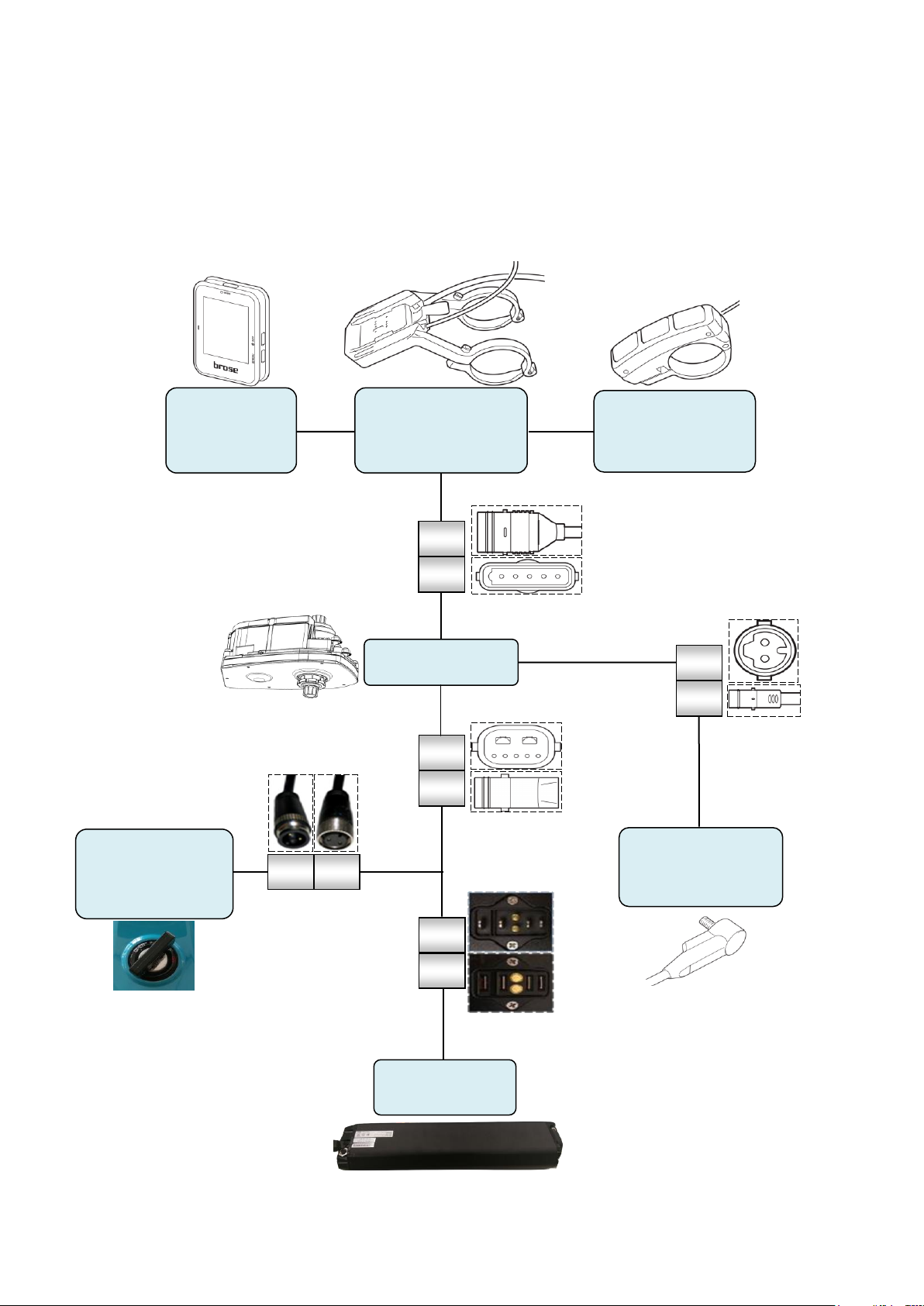
Electronic components connection
The following figureshows theconnectionof all bike’s electronic components
Battery
F
M
F
M
HMI Docking
Handlebar
Switch
HMI
Display
Speed
Sensor
F
M
Battery Key
Lock
Motor
F
M
F
M

4
1.2 Symbolsused
Assembly instructions
Please read the instructions thoroughly prior to assembly and follow the safety instructions.
Information
Indicates important information to be observed in the following sections.
Personal protective equipment
Indicates the personal protective equipment that must be worn in the following steps.
Brose scope of delivery
Indicates the parts or materials from Brose's scope of delivery that are to be used in the following steps.
Tools,auxiliary materials and operating supplies
Indicates the tools, auxiliary materials and operating supplies required for the following steps.
Checkpoints
Indicates checkpoints for verifying that the steps have been completed correctly.

5
2
Safety Instructions
This section contains safety instructions and information that must be followed at every step. Observing the information
contained in this section will ensure safe assembly.
2.1
Safety symbols
This document contains symbols indicating possible sources of danger. They help you identify important safety-related
information so that you can act accordingly.
DANGER
Risk of serious injury
Failure to observe this safety information will result in serious injury.
WARNING
Risk of serious injury
Failure to observe this warning may result in serious injury.
WARNING
Risk of serious crush injury
Failure to observe this warning may result in a serious crush injury.
WARNING
Risk of serious injury from electric shock
Failure to observe this warning may result in serious injury caused by an electric shock.
CAUTION
Risk of minor injury or product damage
Failure to observe this warning may result in minor injury or damage to the component or the environment.

6
2.2
Safety instructions
These safety instructions are designed for your protection and to prevent damage to the product or individual compo-
nents. Please read them thoroughly before working on the product:
-
Please retain all safety instructions and information for future reference.
-
Make sure you read and understand the assembly instructions to ensure safe product handling.
-
Please observe the safety instructions. Failure to follow these instructions could put you and others at risk.
-
All components of this product and its safety devices must be properly assembled to ensure correct operation.
-
Alterations and unauthorized modifications to the product and use of unapproved parts are not permitted.
-
Always observe applicable national and international safety, health and operating instructions.
-
Keep the immediate area clear of highly flammable and other combustible materials.
-
Protect the product against unintended activation.
-
Disconnect the power supply before starting to assemble the product.
-
Keep the work area clear of any tools, objects or cables.
-
Always wear suitable personal protective equipment during assembly work.
-
Ensure that insulated tools are used at all times for assembly.
-
Use only the power supply lines designed for this product.
-
Carefully inspect the fully assembled product and check component performance after assembly. Inadequate product
assembly or inspection may result in serious injury.
-
Never change the component design or state without prior agreement with Brose Drives e-Bike GmbH & Co. KG.
Faulty modifications may significantly impair product performance and cause serious injury.
-
Make sure only skilled staff can access components that have not been fully mounted.
-
Always use suitable tools for pulling connectors out of their sockets.
-
Never grab the cables to pull the connectors out of their connection sockets
-
Always use a torque tool for the assembly of bolted joints to prevent damaging aluminum or carbon parts
7
2.3
Necessary skills and training
The following conditions must be met to ensure safe operation:
-
Make sure all staff receive a safety briefing about possible dangers.
-
Only suitably trained and instructed staff should be permitted to carry out assembly work. These employees must
have received a special briefing about possible dangers and been issued with appropriate information on the
Brose e-Bike System.
2.4
Personal protective equipment
The following protective equipment must be worn to ensure safe operation and assembly:
WARNING
Risk of serious injury
Component handling and commissioning may cause crush injuries to limbs.
- Always wear the protective equipment indicated in the sections.
Explanation of symbols
Personal protective equipment
Indicates the personal protective equipment that must be worn in the following steps.
Safety goggles
Wear suitable eye protection when carrying out the work.
Safety shoes
Wear suitable safety shoes when carrying out the work.
Safety gloves
Wear suitable safety gloves when carrying out the work.

8
3
Assembly
This section provides a detailed description of how to assemble the Brose e-Bike System. All references to ‘left’ and ‘right’
are from the rider’s perspective (direction of travel).
3.1 Components
3.1.1
Overviewof components tobefitted
The Brose material number for the relevant component is indicated below the illustrations.
Drive unit Display unit Wiring harness display unit + holder + remote control
unit
B002-0 B003-0
-
C16162
- 3 x C34175
(M8 hex serrated flange
nut)
-
C54764
- C54760 (with assembly material)
Speedsensor Spokemagnet Motor design cover right Motor design cover left
B005-0 B006-0
-
C54738 (with assembly
material)
-
C54757 (with assembly
material)
-
C60330 (with assembly
material)
-
C11692 (with assembly
material)
Spider and chain rings Brose groove nut Brose spider removal cap Crankarms
B008-0 B009-0 B010-0 B011-0
-
Available from different
suppliers
-
C13572
-
C58068
- Available from different
suppliers
B001-0
B004-0
B007-0

9
Wiring harnesses
Battery pack Battery charger
B013-0 B014-0
-
Battery Pack
-
Different models
available
-
Different models
available
-
Different models
available
Take all necessary precautions to avoid damaging components, cables and coatings during assembly.
WARNING
Risk of serious injury
Always wear the personal protective equipment indicated during assembly.
- Watch out for rotating components during assembly. Even when idle, they may move and trap limbs,
causing crush injuries.
3.2 Fittingthebatterypack
The Brose e-Bike System can be combined with different battery packs. Please refer to manufacturer’s instructions for
details on assembly.
3.2.1
Fittingthemountingrails
Please refer to the manufacturer's instructions for assembling the relevant components.
These instructions do not provide any information about their assembly.
3.2.2
Fittingthebatterypack
Please refer to the manufacturer's instructions on fitting and commissioning the battery pack.
These instructions do not provide any information about fitting and commissioning.
3.2.3
Fittingthebatterypack connectorcable
CAUTION
Risk of product damage
Make sure that the connecting cables are correctly routed in the drive unit housing.
-
Do not bend or pinch connecting cables.
-
Check the shape coding before assembly.
-
Route cables according to your own specifications.
Insert the relevant connectors into the sockets in the drive unit.
-
Route cables according to your own specifications.
-
For more information, see “Cable assignment” on page 11.
B012-0

10
3
Nm
1
2
A
B015-0
3.3
Drive unit
-
Driveunit(C16162)
-
3 x M8 hex serrated flange nut (C34175)
-
Torque wrench
-
SW 13 nut driver
-
M8 hex serrated flange nut = 25-30 Nm
3.3.1
Fittingthedriveunit
Make sure the assembly position is correct
when fitting the drive unit.
Take care to avoid bending or pinching any
existing cables during assembly.
Place drive unit (1) into the drive
mount (2) from the right (in direction of
travel).
-
Make sure that the through holes (A) are
lined up.
-
Check that the drive unit (1) runs
smoothly and has some play after positi-
oning in the drive mount (2).
Use hex nuts (3) to secure drive unit (1).
-
Tighten hex nuts (3) with the correct
torque.
Cable routing
-
Route cables according to your own spe-
cifications. For more information, see
“Cable assignment” on page 11.

11
A
B
C
D
E
F
G
3.4
Cable assignment
3.4.1
Generalinformationoncablerouting
CAUTION
Risk of product damage
Make sure that the connecting cables are correctly routed in the drive unit housing.
-
Do not bend or pinch the connecting cables.
-
Route cables according to your own specifications.
3.4.2
Cableassignmentplan
Select cable length and route cables accor-
ding to your own specifications.
Overview
1)
Battery pack
2)
Rear light
3)
Front light
4)
Speed sensor
5)
Display and remote control unit
6)
e-Bike
Insert connectors into the sockets in the
drive unit.
Observe shape coding.
Insert connector without applying force
until it clicks into place.
Use dummy plugs for non-assigned
sockets.
-
Dummy plugs are available for position 2,
3 and 6.
-
Dummy plugs are not shape-coded.
The table on the right-hand side provides an
overview of the drive unit's connectors and
dummy plugs (front and side view).
A)
Battery pack connector (C50491)
B)
Connector for display and remote
control unit (C50492)
C)
e-Bike connector (C50497)
D)
5-pin dummy plug (C51636)
E)
Front light connector (C50494)
F)
Rear light connector (C50495)
G)
Connector for speed sensor (C50496)
H)
2-pin dummy plug (C51644)
H
B017-0
1
4
2
3
5
6
B016-0

12
3.5
Display unit
-
Wiring harness + holder + remote control unit, supplied with 2 x M3x16 hexagon socket screws and
1 x M3x10 hexagon socket screw (lock screw) (C54760)
-
Display unit (C54764)
-
SW 2.5 hexagon socket wrench
-
Torque wrench
-
M3x16 hexagon socket screw = 0.5 Nm
-
M3x10 hexagon socket screw (lock screw) = 0.3-0.5 Nm
-
Suitable for handlebar diameter: 31.8 mm
3.5.1
Fittingtheholderanddisplayunit
Check the specified handle bar diameter
beforeassembly.
Use suitable rubber pads for smaller hand-
lebars.
Position clamping brackets (1) in the
middle of the handlebar.
-
Fold the two halves (2) of the bracket
around the handlebar and secure lightly
with hexagon socket screws (3).
Align holder and tighten hexagon socket
screw(3).
-
Check the distance between the clam-
ping brackets is as specified.
-
Make sure that you apply the specified
torque.
Route cables according to your own specifi-
cations and connect with drive unit. For more
information, see “Cable assignment” on
page 11.
Use guide grooves provided in the holder
when mounting the display unit.
Place display unit (4) with guide groove
(A)
in the guide opening (B) of the holder.
-
Push display unit (4) down until it clicks
into place.
Optional
-
The lock nut prevents unwanted removal
of the display unit.
-
Screwlocknut(5)intotheholderfromthe
bottom.
-
Make sure the thread of the lock nut (5) is
slightly below the hole and not sticking
out.
5
B018-0
1
2
3
1
1
4
A
B
13
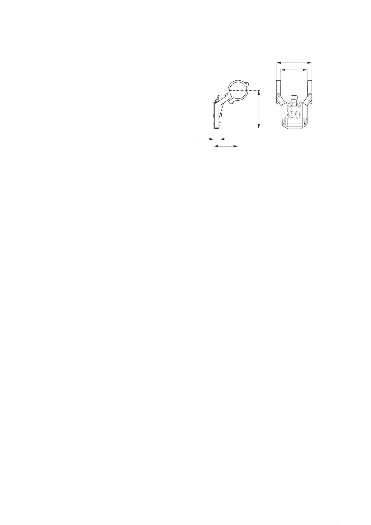
The figure on the right-hand side shows
the dimensions of the holder for the
display unit.
B019-0
66
50
11.45
45.5
71.93

14
3.6 Remotecontrolunit
-
Wiring harness + holder + remote control unit, supplied with 2 x M3x16 hexagon socket screws and
1 x M3x10 hexagon socket screw (lock screw) (C54760)
-
SW 3 hexagon socket wrench
-
Torque wrench
-
M4x12 hexagon socket screw = 0.1-0.3 Nm
-
Suitable for handlebar diameter: 22.2 mm
3.6.1
Fittingtheremotecontrolunit
Check the specified handlebar diameter
beforeassembly.
The remote control unit can be positioned
on the left or right side of the handlebar.
Run the cable (2) from the remote control
unit (1) according to the required handle-
bar position.
Right handlebar position
Run the cable (2) from the left side of the
remote control unit (1).
Left handlebar position
Runthe cable (2)from therightsideofthe
remote control unit (1).
Position remote control unit (1)
on handlebar.
-
The screw connection faces away from
the direction of travel.
Fold clamping bracket (3) around
handlebar.
Secure remote control unit (1) with hexa-
gon socket screw (4).
-
Make sure that you apply the specified
torque.
B021-0
2
1
4
3
B020-0
18
19.75
46

15
3.7 Speedsensorandspokemagnet
-
Speed sensor with M5x12 Torx screw (C54738)
-
Spoke magnet with M4x6 cross-recessed screw (C54757)
-
Torque wrench
-
Torx T 20
-
PH02 cross-recessed screw drive
-
M5x12 Torx screw = 0.8 Nm
-
M4x6 cross-recessed screw = 3 Nm
-
Optimal distance speed sensor/spoke magnet = 5-17 mm
3.7.1
Fittingthespeedsensorandspokemagnet
The speed sensor can only be fitted into the
appropriate frame mount adapter.
Remove protective cap (1).
Place speed sensor (2) into the frame
mount adapter on the left chainstay.
Secure speed sensor (2) with Torx
screw(3).
Replace protective cap (1).
Line spoke magnet up with slot (5) on
spoke.
-
The flat side of the spoke magnet (5)
should be facing the speed sensor (2).
Center spoke magnet (5) along the line
marking and secure with cross-recessed
screw(4).
-
Route cables according to your own spe-
cifications and connect to drive unit.
-
For more information, see “Cable assign-
ment” on page 11.
3.7.2
Frontandrearlight
CAUTION
Risk of product damage
Make sure that the connecting cables are correctly routed in the drive unit housing.
-
Do not bend or pinch connecting cables.
-
Route cables according to your own specification.
Insert the relevant connectors into the sockets in the drive unit.
-
Route cables according to your own specifications.
-
For more information, see “Cable assignment” on page 11.
3
1
2
5
4
B022-0
16
3.8 Fittingthemotordesigncovers
-
Right-hand motor design cover with 3 x M4x8 hexagon socket screws and 2 x M4x6 hexagon socket
screws(C60330)
-
Left-hand motor design cover with 6 x M4x30 hexagon socket screws (C11692)
-
SW 3 hexagon socket wrench
-
Torque wrench
-
M4x6 hexagon socket screw = 0.1-0.3 Nm
-
M4x8 hexagon socket screw = 0.1-0.3 Nm
-
M4x30 hexagon socket screw = 0.1-0.3 Nm
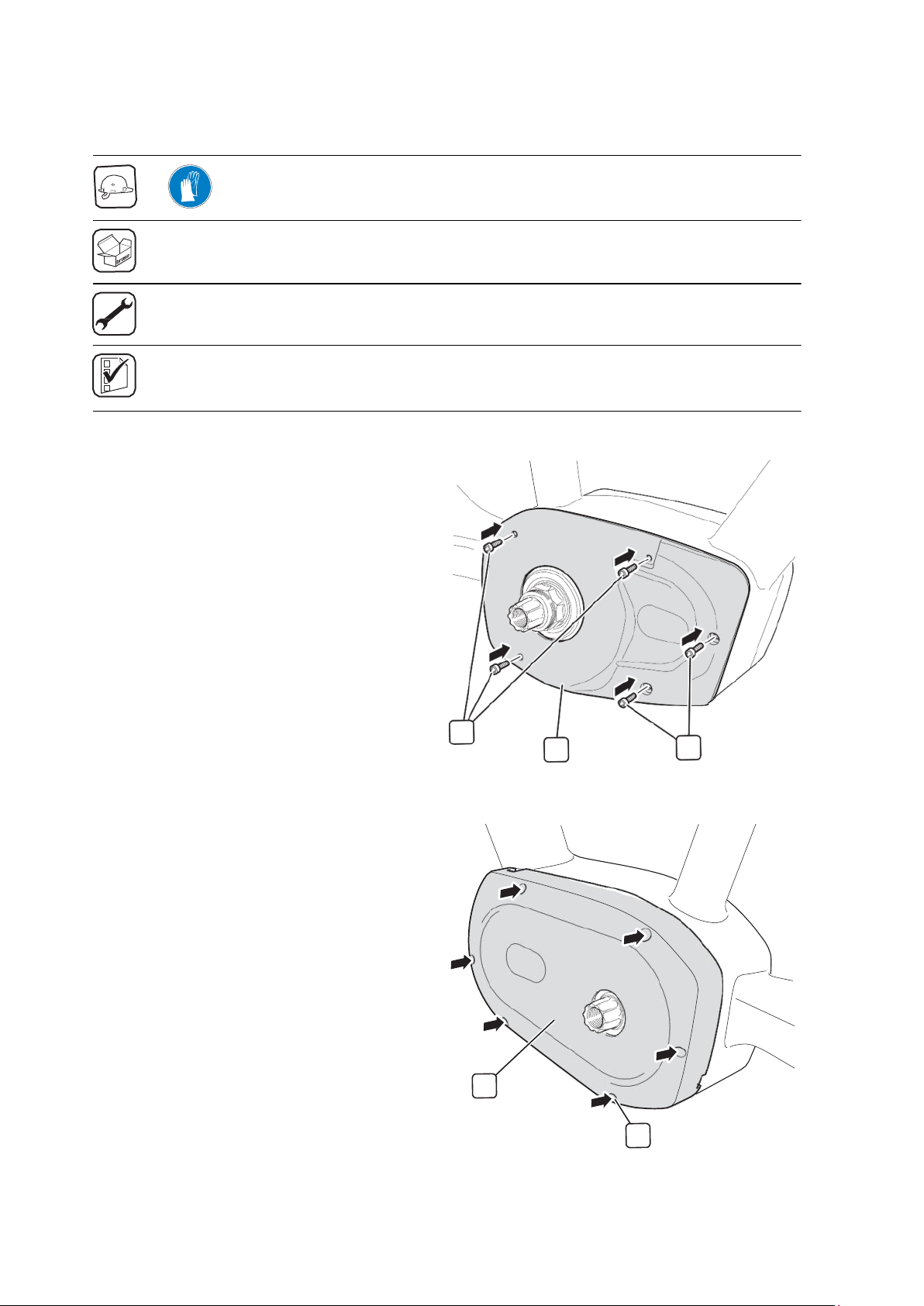
3.8.1
Right-handmotordesigncover
All references to ‘left’ and ‘right’ are from the
rider's perspective.
Position the motor design cover (2) so
that the screw holes line up.
Use M4x8 (1a) and M4x6 (1b) hexagon
socket screws to attach the motor design
cover to the drive unit.
3.8.2
Left-handmotordesigncover
All references to ‘left’ and ‘right’ are from the
rider's perspective.
-
Check that the cables are correctly rou-
ted before fitting the motor design
cover(1).
-
For more information, see “General infor-
mation on cable routing” on page 11.
Position the motor design cover (1) so
that the screw holes line up.
Use M4x30 hexagonsocketscrews (2)to
attach the motor design cover (1) to the
drive unit.
1a
2
1b
B023-0
1
2
B024-0
17
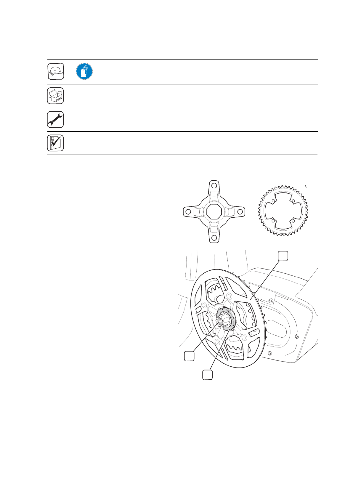
3.9 Fittingthespider,chainringand groovenut
-
Brose groove nut (C13572)
-
Torque wrench
-
Bottom bracket tool for ISIS bottom bracket
-
Brose groove nut = 25-30 Nm
3.9.1
Connectingthespiderandchainrings
Assemble spider and chain rings accor-
dingtomanufacturer'sspecifications.
3.9.2
Fittingthespiderandchainringunit
-
Make sure that you apply the specified
torque.
Mount pre-assembled unit consisting of
spider and chair ring (1) on driveshaft (2).
Screw on Brose groove nut (3) and
secure with bottom bracket tool.
Mount drive chain according to your own
specifications.
Optional
For double chain rings, mount front
derailleur according to manufacturer's
specifications.
B025-0
1
2
3
B026-0

18
3.10 Fittingthecrankarmsandpedals
-
Torque wrench
-
SW 8 hexagon socket wrench
-
Hexagon socket screw (dimensions and torque according to manufacturer's specifications)
3.10.1
Fittingthecrankarms
Before fitting the crank arms, check that you
have the correct side.
Apply a small quantity of grease to the
ISISconnection (1).
Place crank arm (2) on drive shaft.
Secure crank arm (2) with hexagon
socket screw (3).
-
Make sure that you apply the specified
torque.
Repeat these steps to fit the second
crank arm.
-
Check for proper meshing and correct
positioning of second crank arm (offset
by 180°).
3.10.2
Fittingthepedals
Before fitting the pedals, check that you have the correct side.
Fit pedals according to manufacturer's specifications.
2
3
1
B027-0
19
4
Disassembly
DANGER
Risk of electric shock
Disconnect the power supply before starting to disassemble the product.
Remember to always remove the battery pack before working on the Brose e-Bike System.
Take care not to damage components, cables and coatings during disassembly. The referenced sections mainly relate to
specified tools and work steps and are intended for guidance only.
4.1 Crankarmsandpedals
-
SW 8 hexagon socket wrench
-
Standard puller if necessary
4.1.1
Removingthepedals
Remove pedals according to manufacturer's specifications.
4.1.2
Removingthecrankarms
Please follow the manufacturer's instructions when removing the crank arms.
Loosen hexagon socket screws and remove crank arms on both sides.
-
Use standard puller if necessary.
-
For more information, see “Fitting the crank arms” on page 18.
20
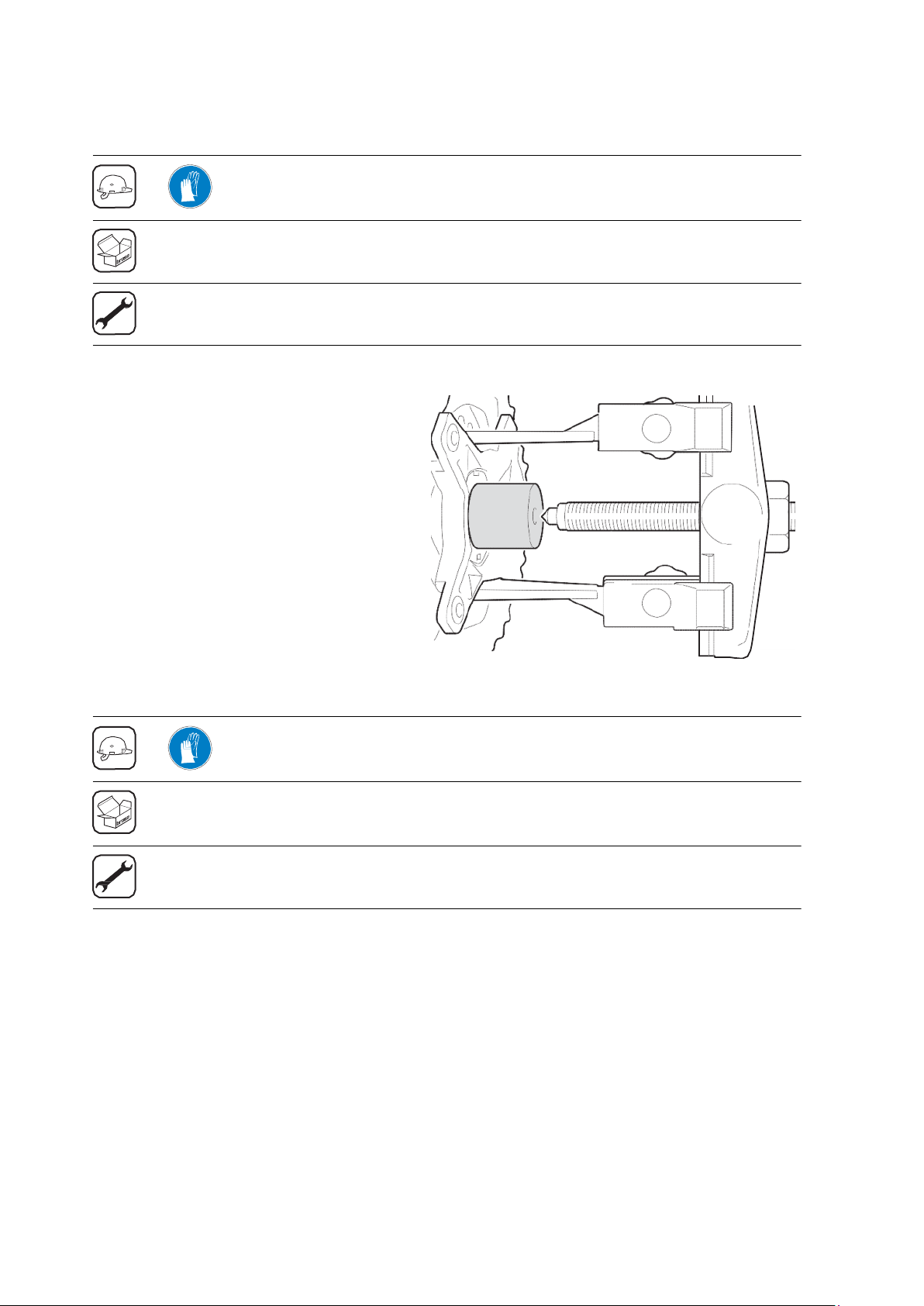
4.2 Spider,chainringandgroovenut
-
Brose groove nut (C13572)
-
Bottom bracket tool for ISIS bottom bracket
-
Standard puller
4.2.1
Removingthespiderandchairringunit
Please follow the manufacturer's instructions
when removing the spider and chain ring unit.
Loosen Brose groove nut with ISIS
bottom bracket tool and remove.
Place Brose spider removal cap on
hollow shaft.
Position puller between spider arms.
-
Loosen spider and chain ring unit and
remove.
-
For more information, see “Fitting the spi-
der and chain ring unit” on page 17.
4.3 Motordesigncovers
-
Right-hand motor design cover with 3 x M4x8 hexagon socket screws and 2 x M4x6 hexagon socket
screws(C60330)
-
Left-hand motor design cover with 6 x M4x30 hexagon socket screws (C11692)
-
SW 3 hexagon socket wrench
4.3.1
Removingtheleft-andright-handmotordesigncovers
Secure motor design covers before loosening the hexagon socket screws to prevent them from falling
and getting damaged.
Loosen and remove hexagon socket screws on both sides.
-
For more information, see “Right-hand motor design cover” on page 16.
-
For more information, see “Left-hand motor design cover” on page 16.
B028-0
Other manuals for TRB1
2
Table of contents
Other BESV Bicycle manuals


