BESV PS1 User manual

Quick Assembly Guide - BESV PS1
Quick Assembly Guide
BESV PS1
V. 1.0, Jan. 2015

Quick Assembly Guide - BESV PS1
1
Contents
1.
What’s in the Box.........................................................................................................................................2
1.1
Main Box Contents............................................................................................................................2
1.2
Accessory Box Contents..................................................................................................................2
2.
Assembly Procedures.................................................................................................................................3
2.1
Front Wheel........................................................................................................................................3
2.2
Steering Column Extension Tube with Stem................................................................................5
2.3
Set Up the Handle Bar......................................................................................................................6
2.4
Front Fender and Headlight.............................................................................................................7
2.5
Pedal.................................................................................................................................................10
2.6
HMI....................................................................................................................................................11
2.7
Battery...............................................................................................................................................13
2.8
Saddle & Seat Post.........................................................................................................................14
2.9
Rear Light.........................................................................................................................................15
3
Checklist......................................................................................................................................................16

Quick Assembly Guide - BESV PS1
2
1. What’s in the Box
1.1 Main Box Contents
1. Main Bike Assembly
2. Accessory Box
3. Saddle/Seat Post Set
4. Front wheel
1.2 Accessory Box Contents
Parts in the accessory box:
1. Product Documentation
2. Charger
3. Human Machine Interface (HMI)
4. Headlight
5. Pedal
6. Rear light
7. Quick release (QR) for the front wheel
8. Front Fender Support
9. Steering column extension tube

Quick Assembly Guide - BESV PS1
3
2. Assembly Procedures
2.1 Front Wheel
2.1.1 Unpack the front wheel and the main
bike assembly.
2.1.2 Insert the wheel into the fork end.
Attention: The disk should be placed
between the brake pads.

Quick Assembly Guide - BESV PS1
4
2.1.3 Set the quick release (QR)
Unscrew the nut and spring from the QR
and insert the QR stem from the left side of
the bike.
Attention: The quick release handle should be on the left side of
bike.
2.1.4 Tighten the nut.
Place the spring back in the QR stem and tighten the nut until you
encounter resistance. Then loosen 1/4 turn.
Note: The tapered end of the spring should be facing inward.
2.1.5 Lock the QR
Lock the QR by pushing the handle
upwards until parallel with fork. Turn
the wheel and verify the rotation is
smooth.
Quick Assembly Guide - BESV PS1
5
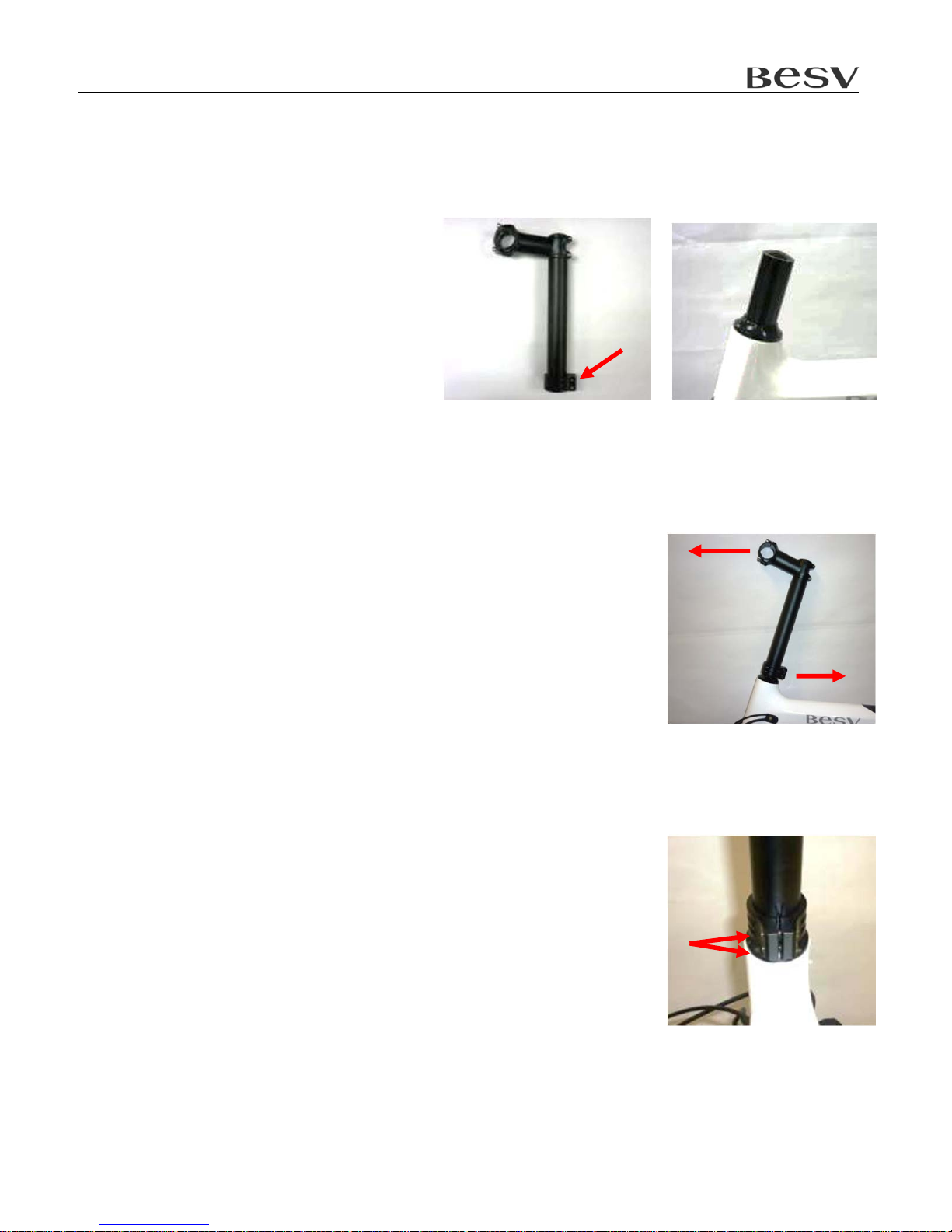
2.2 Steering Column Extension Tube with Stem
2.2.1 Insert the extension tube (a)
into the front fork (b).
2.2.2 Adjust the alignment of the tube
The tube and stem should face forward. The notch of clamp (d)
must face backward.
2.2.3 Tighten the screw (c) beside the clamp (d)
*The torque is 7N-m。
a
b
d
c
Quick Assembly Guide - BESV PS1
6
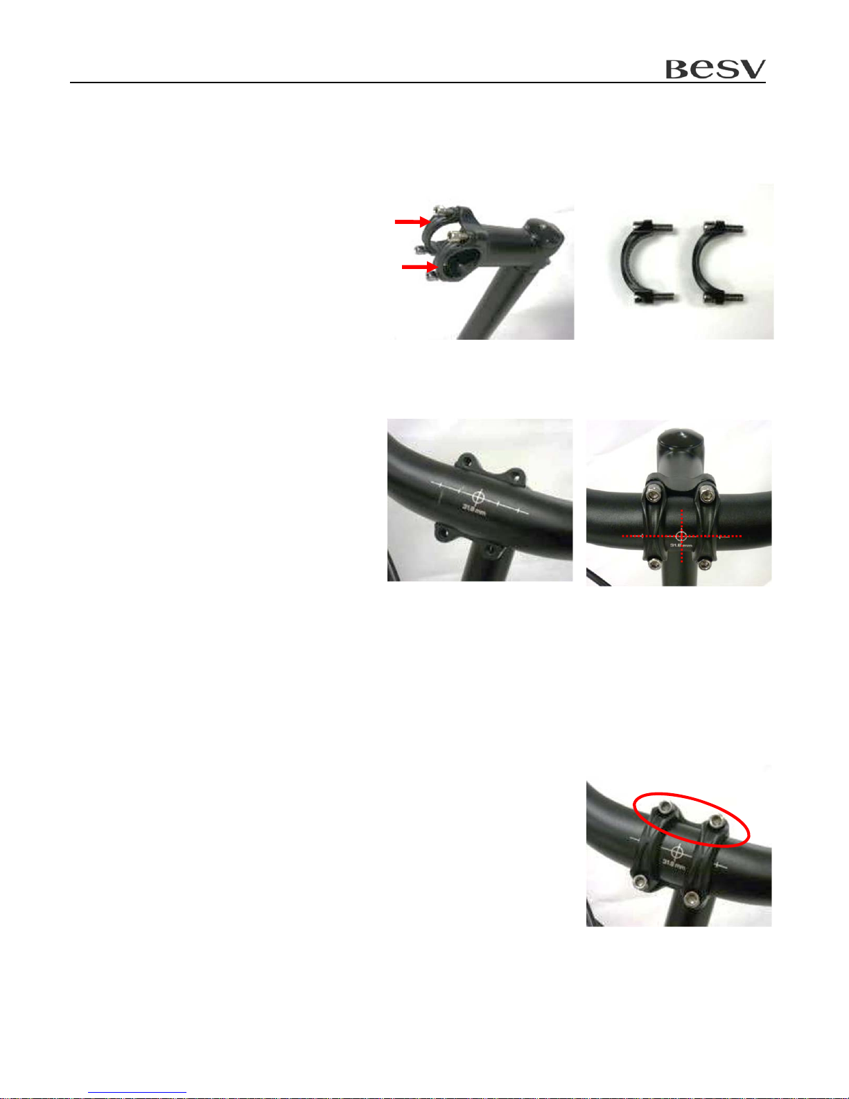
2.3 Set Up the Handle Bar
2.3.1 Take the brackets(e) off the stem
2.3.2 Align the handle bar.
Put the handle bar into stem and
lock the brackets but not tighten it.
Refer to the markings on the
handle bar and align it with the
center of the lock ring.
2.3.3 Tighten the brackets of the stem
Tighten the upper screw until the gap become 0.5mm, then
tighten the lower screw with 6N-m torque.
e

Quick Assembly Guide - BESV PS1
7
2.4 Front Fender and Headlight
2.4.1 Fender parts introduction
(f) Front fender
(g) Fender support
(h) Nylon nut.
(i) M5 screw
2.4.2 Assemble the fender first
Assemble the part (g), (f), (i) as right
picture show.
Note that nylon nut (h) should be inside the fender.
f
g
h
i
g
i
f
h

Quick Assembly Guide - BESV PS1
8
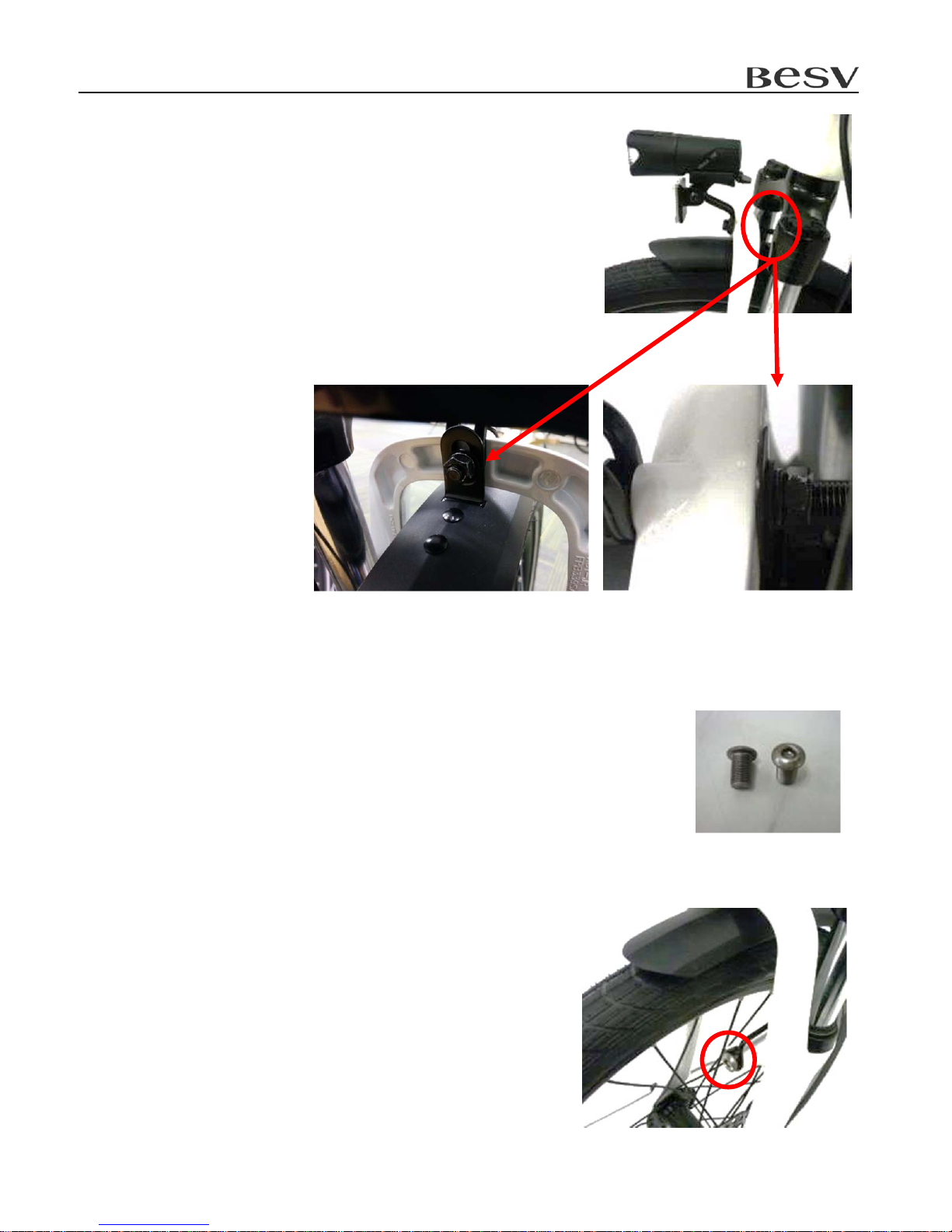
2.4.3 Positon the fender from back to front within the
gap between wheel and fork.
Attention: The brake cable must be kept to the
outer left of the fender support
2.4.4 Push the fender forward until the hanger
touches the fork.
2.4.5 Introduction of headlight parts
(j) Headlight
(k) M6*L35 screw
(m) Flat washer
(n) Spring washer
(p) M6 Nut
j
km n p
Quick Assembly Guide - BESV PS1
9
2.4.6 Insert the screw (k) from the front and through the
light, fork, and the fender hanger. Sequentially from
(m), (n), (p) and tighten them.
2.4.7 Secure the front fender support to the fork
After adjusting the space between the fender and the wheel, use
the M10 screw to secure to the fork.

Quick Assembly Guide - BESV PS1
10
2.5 Pedal
2.5.1 Take out the pedal.
2.5.2 Set up the right pedal
Note: There is a mark “R” on one of the pedal.
Assemble it onto the right crank clockwise.
2.5.3 Set up the left pedal
Take another pedal and assemble it to the left crank
counterclockwise.
R
Quick Assembly Guide - BESV PS1
11
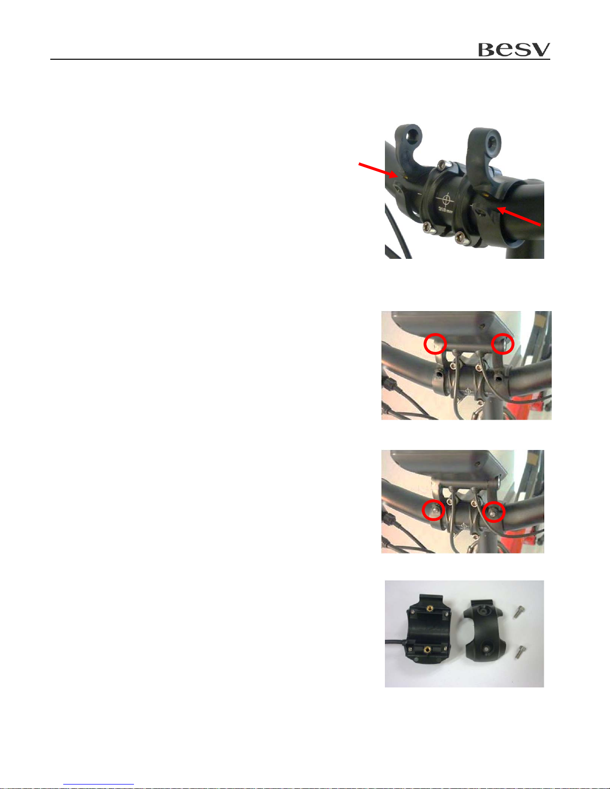
2.6 HMI
2.6.1 Set up the two brackets.
The C type notch face forward and lock onto the
handle bar. Keep the screw loose for now.
*Note the bracket location.
2.6.2 Set up the HMI
Put the HMI in the bracket and adjust the angle.
Tighten both sides with a flat head screwdriver.
2.6.3 Adjust the angle and tighten the bracket screws.
Note: Do not over tighten.
2.6.4 Take apart of switch’s upper and lower housing by
taking off the screws.

Quick Assembly Guide - BESV PS1
12
2.6.5 Set up the Switch
Set up the switch and cable as shown in
the picture.
Place the switch close to the left brake
lever.
Assemble the lower case and tighten the
screw after adjusting the angle.
2.6.6 Connect the HMI.
Connect the HMI to the corresponding
green connector.
Quick Assembly Guide - BESV PS1
13
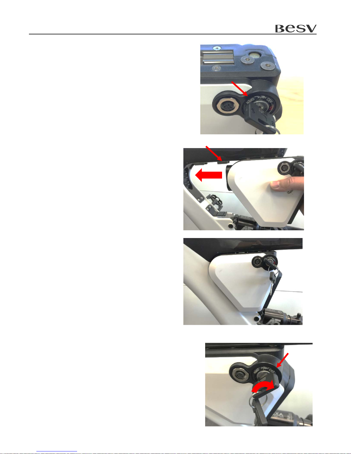
2.7 Battery
2.7.1 Insert the key and turn it to the “OPEN” position.
2.7.2 Aligning the battery with the metal rail,
slide the battery in until it is firmly connected to
the socket.
2.7.3 Push the key in and turn it to “OFF” position to
lock the battery in place.
Quick Assembly Guide - BESV PS1
14
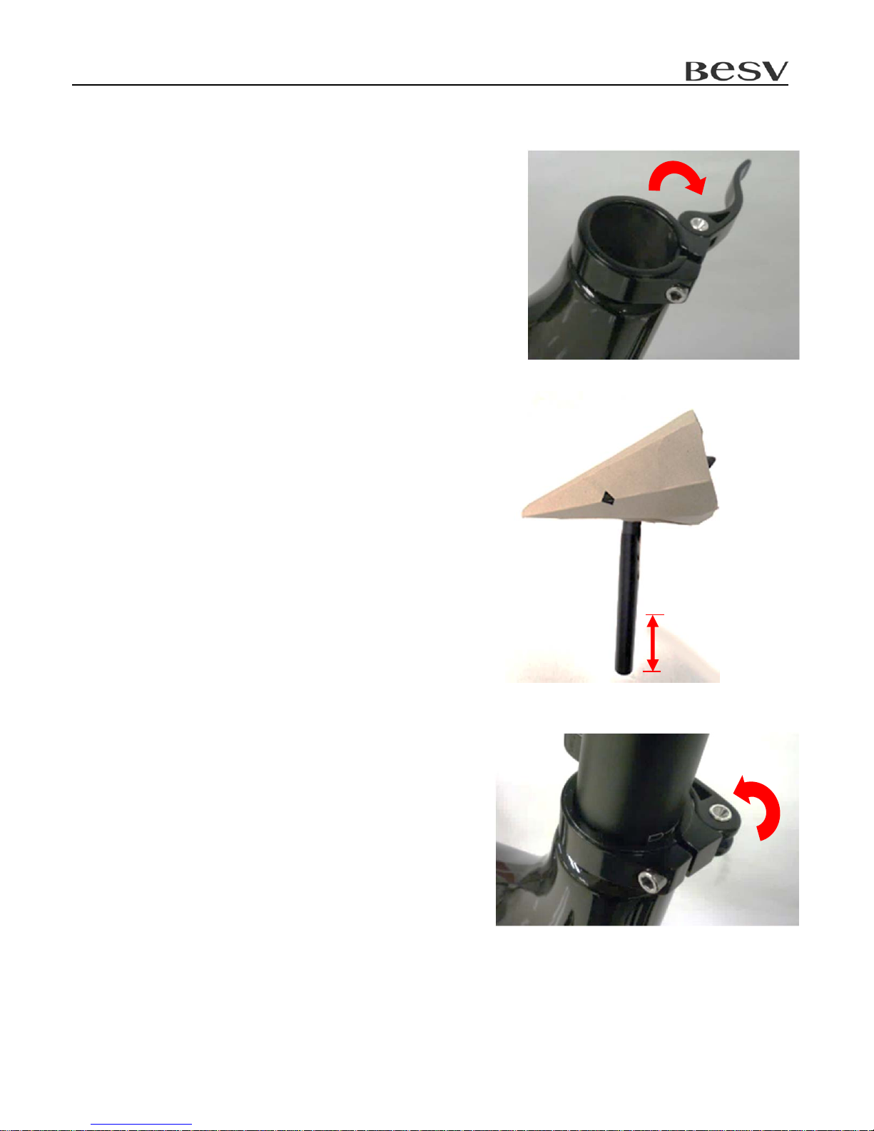
2.8 Saddle & Seat Post
2.8.1 Open the seat post clamp and insert the seat post.
Attention: the depth of the seat post. The seat
post must be inserted at least 10cm (3.9inch).
2.8.2 Set the saddle face forward and adjust the
height. Lock the seat post clamp.
10cm(3.9inch)

Quick Assembly Guide - BESV PS1
15
2.9 Rear Light
2.9.1 Introduction of the rear light parts.
(1) Rear light
(2) Bracket upper housing.
(3) Bracket lower housing & reflector
(4) M4 Nut*2
(5) M4*L15 Screw*2
2.9.2 Bracket.
Put the M4 nut into bracket upper housing.
Set under the saddle.
2.9.3 Combine upper and lower housing by M4 nut.
2.9.4 Insert the rear light into the bracket rail.
5
24
3
1
Quick Assembly Guide - BESV PS1
16
3 Checklist
3.1 Check the tire pressure is normal.
3.2 Check the function of the brakes, derailleur, and chain.
3.3 Check the function of the electric module and the battery power. Please refer to PS1 user
manual.
Table of contents
Other BESV Bicycle manuals


