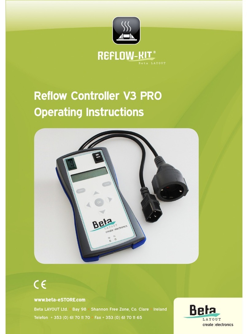
Beta Layout Reflow User manual


Instruction Manual
Reflow-Controlle
r
Contents
1. General Advice .....................................................................................1
1.1. Warranty and Liability ...............................................................................1
2. Safety Information................................................................................2
2.1. Intended use..............................................................................................2
2.2. Safety Instructions.....................................................................................2
3. Introduction...........................................................................................4
4. Overview ..............................................................................................5
5. Technical Data......................................................................................5
6. Command buttons ...............................................................................5
7. Operation ..............................................................................................6
7.1. Soldering procedure..................................................................................6
7.2. Learning Mode..........................................................................................7
7.3. System Self-test........................................................................................8
7.4. Temperature calibration............................................................................8
7.5. Computer interface ...................................................................................9
7.6. Settings......................................................................................................9
7.7. Commands..............................................................................................10
7.8. Settings and Calibrations........................................................................11
8. Maintenance and disposal ................................................................13
9. Guarantee............................................................................................14

Instruction Manual
Reflow-Controlle
r
Page 1 of 14
1. General Advice
Please read this instruction manual right through before installation. It contains
important information about the functioning, operation and care of the Reflow-
Controller.
Notice:
This document is based on the available knowledge at time of going to print. We
accept no liability for the inaccuracy or incompleteness of the information
contained within this document. We reserve the right to make technical changes
as progress demands. This documentation and the information contained within it
are subject to copyright and may not be reproduced, or made accessible to a third
party, in part or in whole, without the written consent of the authors.
1.1. Warranty and Liability
In principle our general sales and delivery conditions apply. Beta LAYOUT Ltd.
denies any liability, jointly or severally, for damages to property or persons caused
by any of the following:
usage other than that for which product is intended,
innappropriate installation, operation or usage,
neglect of the advice, requirements and prohibitions outlined in the manual,
arbitrary structural changes to the product,
self-made sub-standard repairs.
The warranty is deemed to have expired in the case of damages resulting from
neglect of the operating instructions. We accept no liability for any damages so
caused.

Instruction Manual
Reflow-Controlle
r
Page 2 of 14
2. Safety Information
2.1. Intended use
This product may only be used in the control of a Reflow Oven.
Any usage of this product other than that described above is likely to lead to
damage including short-circuiting, fire, electric shocks etc. It is forbidden to alter
and/or convert the entire product in any way.
This product fulfills the legal, national and European requirements. All company
names and product designs are registered trademarks of the respective owners.
All rights reserved.
Acquaint yourself with the operating instructions of the CONTROLLER, which you
will find on the CD supplied with the Reflow oven.
2.2. Safety Instructions
Any damage caused by neglect of the operating instructions renders any
guarantee/warranty null and void! We accept no liability for any damages so
caused!
We accept no liability for any special or personal injuries caused by inappropriate
handling or neglect of the safety instructions. In such cases the
warranty/guarantee is null and void.
• For safety and copyright (EU) reasons no arbitrary changes or alterations to
the product are permitted. Never disassemble the unit!
• The product is designed for operation through the mains supply only
(230V~/50Hz). Must be properly earthed. Connect the CONTROLLER to a
socket using the supplied protected plug only.
• This product is not a toy and is not intended for use by children. Operate the
product out of the reach of children, same goes for storage. Children may
attempt to insert items into the openings on the unit, risking a lethal electric
shock!
• The product is suitable for dry conditions only, do not allow it to become damp
or wet. Never operate the product outdoors or in humid conditions, never
touch it with damp or wet hands! Danger of lethal electric shock!
• The product should not be operated unsupervised.

Instruction Manual
Reflow-Controlle
r
Page 3 of 14
• Do not operate the product in environments in which flammable gases,
steams or types of dust are present or could be present. Danger of fire and
explosion!
• The product is intended for private use only and is not intended for
commercial use.
• The product is suitable only for the regulation of an integrated Reflow Oven.
Never attach different devices.
• The product must only be connected to the mains via the unipolar socket at
the front. Even if the product is switched off, mains voltage can remain in the
plug socket and the attached equipment.
• Do not use the product with a "circuit breaker" for the attached equipment.
• Before the connection of the product to a PC it should be unplugged from the
mains.
• Handle the product with care, impacts, even by falls from a small height, can
damage it.
• Cease using the unit if the housing of the product becomes damaged. If it is
still connected to the mains then you should not touch either the product or
the attached devices! Firstly break the electric circuit to which the product is
attached (switch automatic circuit breaker off). Only then should the attached
equipment be unplugged; then unplug the CONTROLLER from the socket.
Bring the product to a suitable place of repair or dispose of it in an
environmentally friendly manner.
• Dispose of all packaging carefully, this could become a dangerous hazard for
children.
• If you have doubts over the function, operation or security of the product, then
contact a specialist, do not attempt to work on the unit yourself.

Instruction Manual
Reflow-Controlle
r
3. Introduction
The Reflow Oven CONTROLLER regulates the Reflow-Kit oven. In order to
achieve an optimal soldering result, determined times and temperatures must be
kept when soldering SMD components with flux.
The Reflow-Kit CONTROLLER regulates your oven in such a way that the times
and temperatures are adhered to and an optimal soldering result can be
achieved.
The boards and components are slowly heated in a preheating phase.
Thus mechanical stresses in the board and in the components are avoided.
After the preliminary heating the temperature is increased to just under the
soldering temperature. This allows the volatile components of the flux to escape,
avoiding blistering.
Heat then increases up to soldering temperature. The flux will become liquid and
the componenets will form a connection to the board. The soldering temperature
is accurately adhered to during the soldering phase, so that no damages arise
through overheating.
The CONTROLLER will beep to signal the conclusion of the soldering phase. The
finished soldered board can now be taken from the oven.
Page 4 of 14

Instruction Manual
Reflow-Controlle
r
Page 5 of 14
4. Overview
The Reflow CONTROLLER has a plug housing and connection to the oven. It has
3 command buttons, 6 LED's to display status and errors, and a buzzer.
5. Technical Data
Operating voltage: 230V~/50Hz
Max. connected load: 1500 W
PC-Connection: RS232
Pin 2 = TxD, Pin 3 = RxD, Pin 5 = GND
9600 Baud, 8-bit, NO parity, 1 stop bit, no handshake
6. Command buttons
Off CONTROLLER switched off. Plug socket will
become switched off, current programs
interrupted.
Solder Start the automatic soldering cycle.
Learn An automatic alignment and systems check are
begun. The CONTROLLER learns the
characteristics of the oven in use.

Instruction Manual
Reflow-Controlle
r
Page 6 of 14
7. Operation
7.1. Soldering procedure
• Switch your Reflow oven on to the highest performance level.
• Switch on the upper and lower heating elements and place the grill onto the
middle rail.
• Place the temperature regulator of the oven on highest setting.
• Set the oven timer to > 30 min. The oven does not have to be pre-heated.
The soldering procedure can only start once the oven has a temperature of <
50 °C. If you are soldering several boards in rapid succession, the oven must
be allowed to cool to under 50°C between the individual soldering
procedures.
• For soldering the board is put on the center of the grill. Place the temperature
sensor under, or on, the board in such a way that it touches it. This is to
ensure that the temperature sensor measures the board temperature - and
not the air temperature.
• Close the oven door and check again that the temperature sensor did not slip
from the board.
• Press the solder button to commence automatic soldering procedure.
The LEDs indicate the current status of the procedure:
Preheating Phase Slowly warms up and keeps the board heated for
a time.
Soaking Phase Flux activates. Continues to heat slowly to just
under the melting point of the flux.
Reflow Phase Heat increases quickly up to melting point of flux.
Retaining Phase Temperature is maintained slightly above the
melting point of the flux.
If the soldering procedure is finished all LEDs will switch off and an audio signal
sounds. Open the door of the oven immediately for fast cooling.

Instruction Manual
Reflow-Controlle
r
Warning: The board is still hot.
ADVICE
The automatic soldering process can only begin once the CONTROLLER has
learned the oven characteristics.
Fasten the temperature sensor to a piece of unused board with a wire and put this
directly beside the board being soldered.
TIP
7.2. Learning Mode
Before the oven can be used for soldering, the CONTROLLER must firstly learn
the heating and temperature settings of the closed oven.
The LED will blink to indicate the Learning Mode is underway. This process must
be allowed to finish or the CONTROLLER will not allow the soldering phase to be
selected.
For a successful learning mode you should place a board in the oven and the
temperature sensor under or on the board so that it is touching it. Thereby
ensuring that the temperature sensor measures the board temperature - and not
the air temperature.
Now close the oven and press the learning button. The learning mode LED shines
or flashes during the entire learning mode. The oven is then heated up to 100 °C.
The on/off LED lights up. Once 100 °C is reached, the heating is switched off. The
CONTROLLER now measures how far the oven continues to warm up despite
being switched off. Once all LEDs are switched off the learning mode is finished
and the door can again be opened.
Now the CONTROLLER calculates and stores the characteristics of the oven.
It is now ready for the Reflow soldering process.
Page 7 of 14

Instruction Manual
Reflow-Controlle
r
Page 8 of 14
7.3. System Self-test
After switching on on the CONTROLLER runs a system test.
Sensor test
The temperature sensor is checked. The preheating phase LED will flash, as long
as no temperature sensor is recognized.
Please check the temperature sensor if this LED continues to flash after switching
on the CONTROLLER.
LED Test
In a 1-second pulse all LEDs are successively switched on and off.
Buzzer Test
The audio alarm will sound for 1 second.
7.4. Temperature calibration
The temperature sensor of the Reflow CONTROLLER is preset and does not
have not to be calibrated normally. However, if necessary the Reflow
CONTROLLER can be adjusted to the sensor.
The temperature calibration should be done via a connected PC with the function
"tempoffset" selected. (See page 10)
If a PC is not available, the temperature calibration can also take place
semiautomatically.
To do this you must place a temperature sensor with fast-indicating thermometer
in the Reflow oven.
Press the Learning Mode button. As soon as the On/Off LED comes on, press the
Solder button.
The oven will now heat to full capacity. At the moment where the oven achieves
the preset soldering temperature, press the OFF key.

Instruction Manual
Reflow-Controlle
r
Page 9 of 14
7.5. Computer interface
The Reflow CONTROLLER is equipped with a RS232 interface for connection to
a PC (optional).
The CONTROLLER is connected with a standard commercial cable for serial
interfaces with the PC.
7.6. Settings
Adjust the serial interface of the attached computer to the following parameters:
9600 Baud, 8-bit, NO parity, 1 stop bit, no handshake
After the switching on of the CONTROLLER it announces itself with:
# PCBP-Reflow Controller
# Software Date : Apr 17 2006
# Software Time : 12:20:16
# start selftest
# selftest ready
Type "help" for command list.
The Reflow CONTROLLER can be operated using a terminal software such as
Miniterm (Linux) or Hyperterminal (Windows).

Instruction Manual
Reflow-Controlle
r
Page 10 of 14
7.7. Commands
The Reflow CONTROLLER recognizes the following commands:
help Lists all commands
Arrow keys Shows the allocation of the control keys
tempshow Temperature displayed each second [from 0 to desired
frequency in seconds]
tempshow 5 <enter>
The current temperature is displayed every 5 seconds.
tempshow 0<enter>
Current temperature will not be displayed.
Temperature will be displayed in the format; seconds,
+xxx, degC. e.g. 31, +058, 52°C.
Data is separated by a comma.
This data, if stored on the operating system, can later be
uploaded to a spreadsheet e.g. Excel *.csv format.
If a command is given without parameters then the
current temperature is only displayed once.
debug Show Debug information [parameter 0 or 1]
Internal status information is displayed.
trace Internal status information [Parameter 0 or 1]
Program's internal status is displayed.
settings Gives a list of all set parameters.

Instruction Manual
Reflow-Controlle
r
Page 11 of 14
7.8. Settings and Calibrations
The Reflow CONTROLLER can be adjusted to suit different solder pastes,
different temperature sensors and different oven types. The necessary settings
are entered using the computer interface.
phttemp Temperature of the preheating phase [0 to 254 degrees].
phttemp<ENTER> indicates the current value.
phttemp 120 <ENTER> adjusts the temperature to 120°C
phttime Duration of the preheating phase [0 to 254 sec].
phttime<ENTER> indicates the current value.
phttime 240 <ENTER> adjusts the duration to 240 seconds.
phtpwr Amount of heat of the preheating phase [0 to 100%]
phtpwr<ENTER> indicates the current value.
phtpwr 80 <ENTER> the oven will heat to 80% of capacity.
soaktemp Temperature of soaking phase [0 to 254 degrees]
soaktemp<ENTER> indicates the current value.
soaktemp 165<ENTER> adjusts the temperature to 165°C.
soaktime Duration of soak phase [0 to 254 seconds]
soaktime<ENTER> indicates the current value.
soaktime 240<ENTER> adjusts the duration to 240 seconds.
soakpwr Amount of heat of soak phase [0 to 100 %]
soakpwr<ENTER> indicates the current value.
soakpwr 80<ENTER> oven heats to 80% capacity
reflowtemp Reflow temperature [0 to 254 degrees]
reflowtemp <ENTER> indicates the current value.
reflowtemp 232<ENTER> the temperature adjusts to 232°C.
reflowtime Reflow time [0 to 254 seconds]:
This parameter has at present no meaning. The Reflow phase
is terminated as soon as the adjusted Reflow temperature has
been reached.

Instruction Manual
Reflow-Controlle
r
Page 12 of 14
reflowpwr Reflow capacity [0 to 100 %]
reflowpwr <ENTER> indicates the current value.
reflowpwr 100<ENTER> the oven heats to 100% capacity.
dwelltemp Temperature of the retaining phase [0 to 254 degrees]
dwelltemp<ENTER> indicates the current value. dwelltemp
232<ENTER> the temperature adjusts to 232°C. This
temperature is normally equal to the Reflow temperature.
dwelltime Duration of the retaining phase [0 to 254 sec].
dwelltime<ENTER> indicates the current value.
dwelltime 40<ENTER> adjusts duration to 40 seconds.
dwellpwr Capacity of the retaining phase [0 to 100% ]
dwellpwr<ENTER> indicates the current value.
dwellpwr 100<ENTER> the oven operates at 100% capacity.
tempoffset Temperature sensor adjustment [- 30 to 30degrees].
tempoffset<ENTER> indicates the current value in °C.
tempoffset -3<ENTER> the measured temperature is reduced
by 3°C. 3 degrees less are indicated.
tempoffset 5<ENTER> the measured temperature is
increased by 5°C. 5 degrees more are indicated.

Instruction Manual
Reflow-Controlle
r
Page 13 of 14
8. Maintenance and disposal
The Reflow CONTROLLER is maintenance-free.
The mains fuse should only be changed by a specialist. A safety fuse with the
same technical specs must be used.
The use of repaired safety fuses or bypassing of the safety fuse is not permitted.
Repairs are to be carried out exclusively by an authorized specialist. Obsolete
electronic devices are recyclable materials and do not belong in domestic refuse.
Dispose of the equipment at the end of its life span according to the laws in force.
This instruction manual corresponds to the technical conditions at the time of
going to print. The right to change technology and equipment is reserved.

Instruction Manual
Reflow-Controlle
r
Page 14 of 14
9. Guarantee
This equipment comes with a 1 year warranty. The warranty covers the free
recovery of the defective equipment, due to the use of imperfect material or
factory defect. Large requirements are impossible.
We give neither a guarantee nor accept any liability for damage or consequential
loss in connection with this product. We reserve the right to repair, rework, supply
spare parts or offer a reimbursement of the purchase price.
In the following cases no repair will be offered and the warranty claim expires:
• Alteration and repair attempts to the equipment including arbitrary alteration of
the circuitry
• Unspecified construction, improper storage of components, incorrect wiring of
components such as switch, potentiometer, sockets etc.
• Use of foreign components, not originals belonging to the kit
• Corrosion of copper tracks or solder pads.
• Incorrect assembly and any damages resulting from it
• Overloading of the component assembly
• Damage caused by interference of third parties
• Damage caused by neglect of the operating instructions and the connection
diagram
• Connection to the wrong current or type of current
• Incorrect polarity of the component assembly
• Faulty operation or damage by negligent or abusive treatment
• Defects due to bypassing of safety fuses or the use of wrong safety fuses
In all these cases returns are made at your own cost!
Table of contents
Other Beta Layout Controllers manuals
Popular Controllers manuals by other brands

Altinex
Altinex Wireless Touchscreen Controller CP451-008 user guide
Parker
Parker AC890PX Series User Mounting and Assembly Instructions
Flytec
Flytec P2410W quick start guide

Omron
Omron TJ2-MC64 Hardware reference manual
Linear
Linear PRO Access APeX-II v2.1 Quick programming guide
UHPPOTE
UHPPOTE HBK-A01 user manual
