Beta RS 4T 450 User manual

1USA
RS 4T 400 - 450 - 520
Thanks for you preference, and have a good time! This hand-
book contains the information you need to properly operate and
maintain your motorcycle.
The data and specifications provided in this manual does not constitute an
engagement on the part of BETAMOTOR S.p.A. BETAMOTOR reserves the
right to make any changes and improvements to its models at any moment
and without notice.

2
USA
IMPORTANT
We recommend you to check all the tightenings after the first one
or two hours’ ride over rough ground. Special attention should
be paid to the following parts:
•rear sprocket
•ensure that the footrests are properly fixed
•front/rear brake levers/calipers/discs
•check that the plastics are properly fastened
•engine bolts
•shock absorber bolts/swingarm
•wheel hubs/spokes
•rear frame
•pipe connections
•tensioning the chain
IMPORTANT
For any servicing requirements, please get in contact with Beta-
motor’s authorized service network.

CONTENTS
3USA
CONTENTS
Operating instructions............................................................................. 5
Ecologic guide....................................................................................... 5
Riding safety .........................................................................................6
CHAPTER 1 GENERAL INFORMATION ..............................................7
Vehicle identification data ....................................................................... 8
Tools kit ..............................................................................................10
Steering lock .......................................................................................11
Familiarizing with the vehicle.................................................................12
Moto-GPS “Voyager” (Trail Tech)............................................................ 16
Specifications ......................................................................................17
Electrical system...................................................................................20
Recommended lubricants and liquid .......................................................24
CHAPTER 2 OPERATION .................................................................. 25
Checks to be performed before each ride ...............................................26
Running-in ........................................................................................... 27
Engine start .........................................................................................28
Refuelling............................................................................................ 29
Fuel tank cap....................................................................................... 29
Fuel cock ............................................................................................29
CHAPTER 3 CHECKS AND MAINTENANCE .....................................31
Oil circuit............................................................................................ 32
Changing the gear and clutch oil ...........................................................35
Brakes ................................................................................................36
Tyres...................................................................................................39
Hydraulic clutch ................................................................................... 40
Fork oil ...............................................................................................41
Air Filter.............................................................................................. 44
Spark plug ..........................................................................................45
Carburettor .........................................................................................47
Coolant ..............................................................................................48
Chain .................................................................................................49
Battery................................................................................................50
Cleaning the vehicle............................................................................. 51
Scheduled maintenance vehicle .............................................................52
Prolonged inactivity..............................................................................54

CONTENTS
4
USA
CHAPTER 4 ADJUSTMENTS..............................................................55
Adjusting the home position of the front brake lever..................................56
Adjusting the home position of the brake pedal .......................................56
Adjusting the home position of the clutch lever.........................................56
Adjusting the handlebars ......................................................................56
Gas control adjustment ......................................................................... 57
Checking and adjusting the steering play................................................57
Adjusting fork ...................................................................................... 58
Shock absorber....................................................................................59
Tensioning the chain.............................................................................60
Adjusting the idle speed........................................................................ 61
CHAPTER 5 REPLACEMENTS ............................................................63
Replacing the brake pads .....................................................................64
Replacing the headlight bulbs................................................................66
Tail light..............................................................................................66
CHAPTER 6 TROUBLESHOOTING ....................................................67
Troubleshooting ...................................................................................68

5USA
OPERATING INSTRUCTIONS
•The vehicle must be accompanied by: number-plate, registration document, tax
disc and insurance.
•Do not carry animals, pets or loose objects that can stick out from the vehicle.
•Riding without a crash helmet is forbidden.
•Always ride with the low beam on.
•Any modifications of the engine or other parts resulting in a power and/or speed
increase are punishable by severe sanctions including the confiscation of the vehicle.
•To protect your safety and that of others, always drive carefully and with your helmet
on.
WARNING
Any modifications and tampering with the vehicle during the warranty period exempt
the manufacturer from all responsibility and invalidate warranty.
ECOLOGIC GUIDE
•Every vehicle powered by an internal combustion engine produces an amount of
noise (noise pollution) and gases (air pollution) which varies with the riding style.
•The abatement of noise and air pollution levels is the duty of everybody. Avoid
full-throttle starts, sudden acceleration and abrupt braking. This will reduce noise
emission as well as the wear and tear of the tyres and mechanical parts, and will
also allow a considerable reduction in fuel consumption.

6
USA
RIDING SAFETY
•Observe the Highway Code.
•Always put on and fasten a homologated helmet.
•Always ride with the low beam on.
•Always keep the crash helmet visor clean.
•Avoid wearing garments with hanging ends.
•Do not keep sharp or brittle objects in your pockets while riding.
•Properly adjust the rearview mirrors.
•Always ride in a seated position, with both hands on the handlebars and both feet
on the footrests.
•Always pay attention and do not allow anything to distract you while riding.
•Do not eat, drink, smoke, use a mobile phone, etc. while riding.
•Do not wear headphones to listen to music while riding.
•Never ride abreast with other vehicles.
•Do not tow and avoid being towed by other vehicles.
•Always keep a safe distance from other vehicles.
•Do not sit on the vehicle when it is on its stand.
•Do not start off while the vehicle is on its stand.
•Do not pull out the stand when the vehicle is facing downhill.
•Avoid swaying and wheelies as they are extremely dangerous for your own and
other people’s safety as well as for your vehicle.
•Always apply both brakes on dry roads with no gravel and sand. Using one brake
may be dangerous and cause uncontrolled skidding.
•To reduce the braking distance, always apply both brakes.
•On wet roads and in off-road riding, drive with care and at moderate speed. Take
special care in applying the brakes.
•Do not start the engine in closed places.

1
GENERAL INFORMATION
7USA
CHAPTER 1 GENERAL INFORMATION
CONTENTS
Vehicle identification data ....................................................................... 8
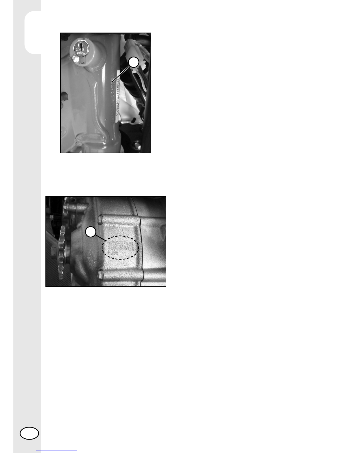
Frame identification ...........................................................................8
Engine identification ..........................................................................8
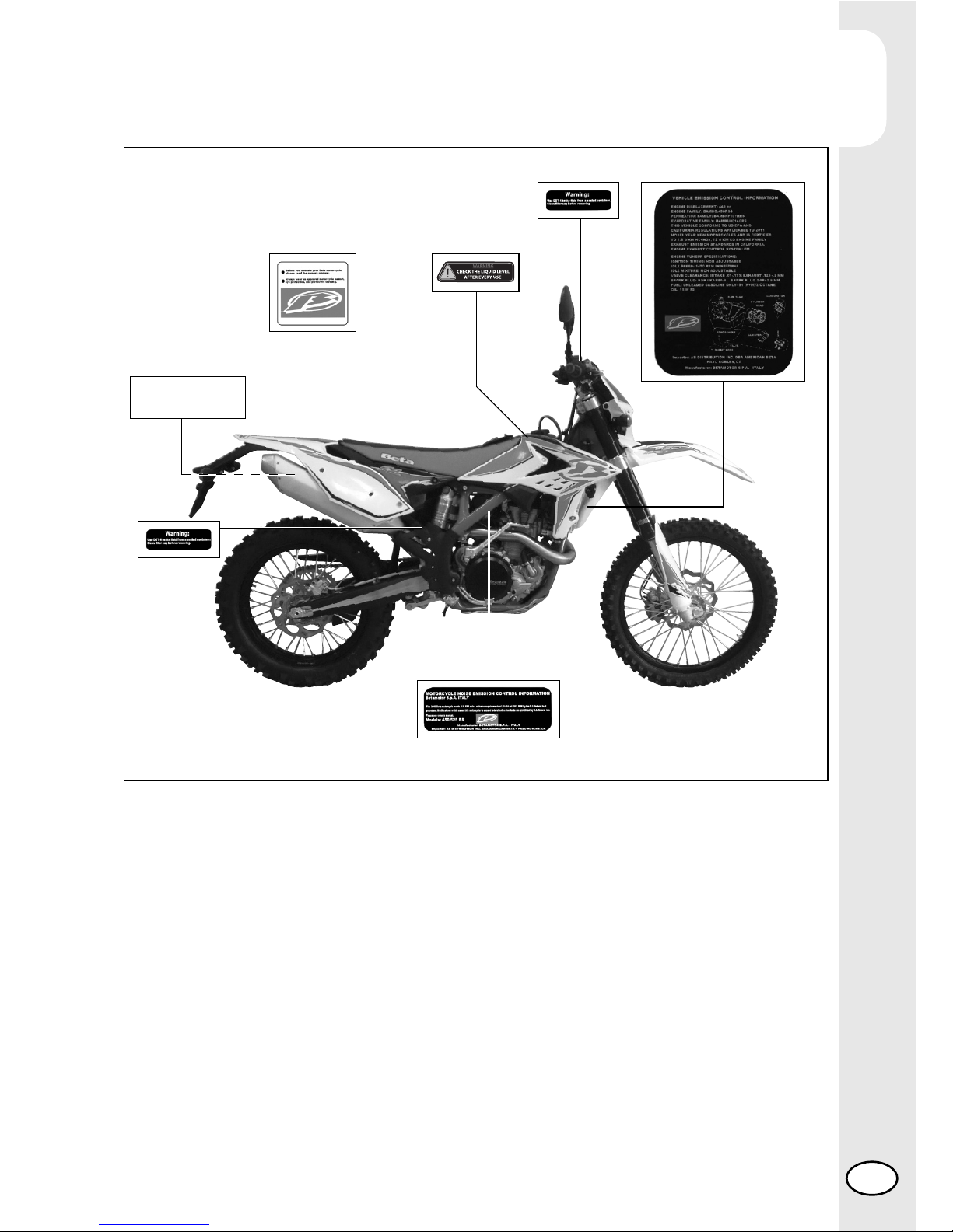
Label location ...................................................................................9
Tools kit .............................................................................................. 10
Steering lock .......................................................................................11
Familiarizing with the vehicle.................................................................12
Main parts:.....................................................................................12
Clutch lever ....................................................................................13
Front brake lever ............................................................................. 13
Gearchange lever............................................................................13
Brake pedal....................................................................................13
Lights and key-switch........................................................................ 14
RH switch .......................................................................................14
LH switch........................................................................................14
Kickstart .........................................................................................15
Side stand ......................................................................................15
Canister filter system ........................................................................15
Moto-GPS “Voyager” (Trail Tech)............................................................16
Removing the lithium battery ............................................................. 16
Specifications ......................................................................................17
Weight........................................................................................... 17
Dimensions ..................................................................................... 17
Tyres..............................................................................................17
Capacities......................................................................................17
Front suspension..............................................................................17
Rear suspension ..............................................................................18
Front brake..................................................................................... 18
Rear brake ..................................................................................... 18
Engine ...........................................................................................18
Electrical system...................................................................................20
Electrical diagram ...........................................................................20
Legend electrical diagram ................................................................ 21
Battery ........................................................................................... 22
Fuse...............................................................................................23
Recommended lubricants and liquid .......................................................24

1
GENERAL INFORMATION
8
USA
VEHICLE IDENTIFICATION
DATA
FRAME IDENTIFICATION
Frame identification data Aare stamped
on the right side of the steering head tube.
ENGINE IDENTIFICATION
Engine identification data Bare stamped
in the area shown in the figure.
WARNING:
Tampering with the identification numbers
is severely punished by law.
B
A

1
GENERAL INFORMATION
9USA
Label RS4T:
1 – Warnings plate
2 – Brake oil plate
3 – Technical plate and vapour recovery diagram
4 – Eco-plate
5 – Noise limit
6 – Liquid level check
1
4
3
2
LABEL LOCATION
2
This BETA exhaust system 2204185 meets U.S.EPA
noise emission requirements of 80dBa for model specific
code Beta 3867700497, 3867710497, 3867660497,
3867670497 and 3867680497
Installation of this exhaust system on motorcycles not
specified may violate U.S. federal law. USFS approved
spark arrester-Screen type ARROW screen type 5205007
5
6

1
GENERAL INFORMATION
10
USA
Get off the male end wrenches and hexa-
gon socket 3.
With these is possible to unscrew the
screw 4.
Pull the left cover of rear fender and unhook
two rubber band 5. Now the toolkit 6is
accessible.
To take the tool kit, push the button 1to
get off the saddle. Pull back the saddle.
Pull the rear side panel 2to disassemble it.
4
1
2
3
6
5
5
TOOLS KIT
The following items are supplied as stand-
ard: operation and maintenance manual,
tool kit (see photo).

1
GENERAL INFORMATION
11 USA
STEERING LOCK
The vehicle is supplied with one key and
a spare to be used for the steering lock.
WARNING:
Do not keep the spare keys in the vehicle.
Keep the keys in a safe and easy-to-reach
place. The code number stamped on the
keys should be copied on this manual (or
elsewhere) so it can be used to ask for
duplicates should both keys be lost.
To engage the steering lock, fully turn the
handlebars to the left, insert the key, press
and turn it fully anticlockwise and then
release it.

1
GENERAL INFORMATION
12
USA
FAMILIARIZING WITH THE VEHICLE
MAIN PARTS:
1 - Fuel tank
2 - Tank cap
3 - Silencer
4 - Rear shock absorber
5 - Headlight
6 - Rear light
7 - Side stand
8 - Fork
9 - Rider’s footrests
10 - Lower bumper
(Bumper kit)
11 - Saddle
12 - Engine
13 - Front mudguard
14 - Number-plate holder
15 - Kick-start
16 - Front side panel
17 - Rear side panel
18 - Fork covers
19 - Rear mudguard
20 - Cover air filter
21 - Blinkers
22 - Key-switch
5
8
21
11
19
14
12
94
63
15 10
13
16
18
20
7
9
21
21
22
17

1
GENERAL INFORMATION
13 USA
CLUTCH LEVER
Clutch lever 1is fitted to the left-hand side
of the handlebars. Screw Acan be used
to alter the home position of the lever (see
Adjustments).
FRONT BRAKE LEVER
Front brake lever 2is fitted to the right-hand
side of the handlebars. Screw Bcan be
used to adjust the home position of the
lever (see Adjustments).
GEARCHANGE LEVER
Gearchange lever 3is fitted to the left side
of the engine.
The positions corresponding to the different
gears are shown in the figure.
The neutral position is between the 1st and
2nd gears.
BRAKE PEDAL
Brake pedal 4is located in front of the
right-hand footrest.
The position of the pedal can be adjusted
to suit the requirements of the driver (see
Adjustments).
A
1
1
2
3
456
3
4
2
B

1
GENERAL INFORMATION
14
USA
LIGHTS AND KEY-SWITCH
To switch on the engine, turn the the key-
switch on 1position. To switch off, turn on
the 0position. The Alight is for the high
beam light. The Blight is for the blinker.
RH SWITCH
Starte button 1is located on the right-hand
side of the handlebars and operate the
electri engine starter. Push the button until
the engine sterts.
Do not press the button 1while the engine
is running.
While button 2turns off the engine.
Caution:
Before turning it on, make sure the switch
2is on ON.
LH SWITCH
Dip switch 3has two positions:
A= Low beam on
B= High beam on
Button 4is for the horn.
Button 5is for the flasher
Shifting lever 6on the left or right activates
the left or right inidcators. When released,
the returns to the central position. Press it
to switch off the indicators.
ON OFF
5
B
0
1
A
2
1
A
B
4
3
6

1
GENERAL INFORMATION
15 USA
6
8
7
KICKSTART
Kickstart 6is fitted to the right-hand side
of the engine.
The upper part of the kickstart can be
oriented.
SIDE STAND
Press down side stand 7with the foot and
lean the vehicle against it.
Ensure that the ground is solid and the
vehicle stands steadily.
If the vehicle is used off-road, the closed
stand can be further fastened by means of
rubber band 8.
Betamotor S.p.A has always been sen-
sitive to environmental protection, and
all vehicles comply with the applicable
regulations on harmful gas emissions and
sound pollution.
CANISTER FILTER SYSTEM
The extra system with a Canister 1emis-
sion filter and vacuum valve 2prevent the
release of vapours into the atmosphere.
1
2

1
GENERAL INFORMATION
16
USA
MOTO-GPS “VOYAGER” (TRAIL TECH)
REMOVING THE LITHIUM
BATTERY
To remove the lithium battery on the
dashboard (see the dashboard user guide
available in the CD-ROM “TRAIL TECH”
provided with the vehicle) follow this steps:
1) unhook the rubber bands 1and
remove the front mask 2;
2) remove the two fixing screws 3;
3) disconnect the dashboard connec-
tors to the electrical system;
4) remove the dashboard.
To refit, perform the above steps in
reverse order.
2
1
3
The dashboard user guide and the “RideLeader GPS File Editor” are available in the
CD-ROM “TRAIL TECH” provided with the vehicle.
NOTE
The circumference of the front wheel is 219mm (8.62in).

1
GENERAL INFORMATION
17 USA
SPECIFICATIONS
WEIGHT
Dry weight RR 400 ...................................113 kg (front 55 Kg; rear 58 Kg)
Dry weight RR 450 - 520 ....................113,5 kg (front 55 Kg; rear 58,5 Kg)
DIMENSIONS
maximum length......................................................................... 2180 mm
maximum width ...........................................................................807 mm
overall height ............................................................................1270 mm
wheelbase................................................................................. 1490 mm
saddle height............................................................................... 940 mm
ground clearance.........................................................................320 mm
footrest height..............................................................................413 mm
FRAME ............ molybdenum steel with double cradle split above exhaust port
TYRES
front rim........................................................................ 21x1,6 - 36 holes
rear rim ...................................................................... 18x2,15 - 36 holes
CAPACITIES
fuel tank..........................................................................................8 liter
fuel type........petrol unleaded, with a minimum octane number of 95 (R.O.N.)
including reserve...........................................................................1,3 liter
coolant circuit...............................................................................1,3 liter
motor oil ....................................................................................0,85 liter
gear oil.................................. 1 liter (10W - 40) - about details see page 35
Dimensions Pressure [Bar]
Front tyre Rear tyre Front tyre Rear tyre
90/90-21 140/80-18
1,5 (road use) 1,8 (road use)
1 (off-road use) 1 (off-road use)

1
GENERAL INFORMATION
18
USA
FRONT SUSPENSION
“SACHS” hydraulic upside-down fork (Ø48 mm shafts)
spring............................................................................................. K 4,8
oil type ................................................................... Motul Factory Line 5wt
oil quantity (from the top, without spring and with fork compressed) ... 110 mm
REAR SUSPENSION
Single shock absorber with compound lever
spring............................................................................................. K 5,2
precharge (spring in its seat) ......................................................... 247 mm
shock absorber stroke................................................................... 135 mm
rear wheel stroke ......................................................................... 290 mm
FRONT BRAKE
Ø 260 mm disc and dual-piston floating caliper
REAR BRAKE
Ø240 mm disc and single-piston floating caliper
ENGINE
Type ................................................. Single cylinder, 4-stroke, liquid-cooled
with countershaft and electric starting
Bore x stroke RR 400........................................................... 95 x 56,2 mm
Bore x stroke RR 450........................................................... 95 x 63,4 mm
Bore x stroke RR 520......................................................... 100 x 63,4 mm
Displacement (cm3) RR 400 ...........................................................398 cm3
Displacement (cm3) RR 450 ........................................................449,4 cm3
Displacement (cm3) RR 520 ........................................................497,9 cm3
Compression ratio RR 400 .............................................................. 12,4:1
Compression ratio RR 450 ............................................................ 11,95:1
Compression ratio RR 520 .............................................................. 12,0:1
Fuel system............................................................................... carburetor

1
GENERAL INFORMATION
19 USA
RR 400 RR 450 RR 520
Carburator type Keihin FCR-MX 39 Keihin FCR-MX 39 Keihin FCR-MX 39
Main jet 175 175 180
Idling jet 45 45 45
Starter jet 85 85 85
Needle OBDTS OBDVS OBDVS
Needle position (from above) 5° 4° 4°
Main air jet 200 200 200
Idling air jet 100 100 100
Mixture control screw 1 + 1/2 1 + 1/2 1 + 1/2
(from fully closed)
Intake jet 50 40 40
Stop NO NO NO
* - This change makes the vehicle not complying with the Highway Code. Use should be limited to private circuits and
routes closed to traffic.
Carburetor
Lubrication ............................................................................. 2 oil pumps
Cooling system ......................................... forced liquid circulation by pump
Spark plug .................................................................... NGK LKAR 8A - 9
Clutch..................................................................................wet, multidisc
Transmission.................................................. 6-speed with front claw clutch
Valve gear .................................................................................. 4 valves
Ignition ................................................................ DC-CDI without trembler,
with digital variable spark advance, Kokusan-type
Starting.............................................................electric starter and kickstart
Version RR 400 RR 450 RR 520
Primary drive 28/76 31/73 31/73
Gear ratio 1st gear 12/31 12/31 12/31
Gear ratio 2nd gear 15/28 15/28 15/28
Gear ratio 3rd gear 19/28 19/28 19/28
Gear ratio 4th gear 20/24 20/24 20/24
Gear ratio 5th gear 27/27 27/27 27/27
Gear ratio 6th gear 28/24 28/24 28/24
Final drive 15/48 15/48 15/48

1
GENERAL INFORMATION
20
USA
ELECTRICAL SYSTEM
ELECTRICAL DIAGRAM
Table of contents
Other Beta Bicycle manuals