BETCO PeroxiDraw User manual

PeroxiDraw™Dispenser
INSTALLATION INSTRUCTIONS
I-883 Pg. 1 of 6
05/05
The PeroxiDraw™Dispensing System is a locking dispensing system that allows the user to dispense Green Earth®Peroxide Cleaner for up
to six different dilutions and applications safely and effectively. Pretipped to use at the right dilution. Simply hang on the wall and start
using the dispenser.
1. PARTS CHECKLIST:
ITEM DESCRIPTION QTY.
A. PeroxiDraw™Assembly 1
B. 1/4” ID Vinyl Supply Tubing & Foot Valve Assembly 1
C. Ceramic Weight 1
D. 1/2” ID X 6’ Long Vinyl Outlet Tubing (For 4 GPM Station Only) 1
E. Outlet Tubing Hanger (For 4 GPM Station Only) 1
F. Drip Tray (For 1 GPM Station Only) 1
G. #10 Screw & Anchor Kit Set (Total 10 Screws & 10 Anchors) 1
H. Metering Tip Kit 1
I. Cabinet Lock Keys 1
J. Hinge 8
2. INSTALLATION: (Refer to Figure 1)
Note: All installations must conform with local plumbing codes and use approved backflow preventers. Pressure indicating
tee is to be installed with existing faucets according to local plumbing codes in the state of Wisconsin and any other
state that requires the use of a pressure indicating tee.
A. MOUNTING AND WATER SUPPLY:
Locate mounting holes on a permanent surface. Drill all of the holes into the drywall using a 1/4” diameter bit for use with
the included #10 screw and anchor set. (If mounting the PeroxiDraw™dispenser to wood and you do not plan to use the
included anchors, drill 1/8” diameter holes.) Insert the anchors into drilled holes and hammer them into the wall until they
are flush with face of wall. Assemble all of the #10 screws with a Phillips screwdriver into the anchors so the screw heads
are sticking out of the wall approximately 1/2”. Mount the PeroxiDraw™dispenser by inserting the screw heads through the
keyhole slots in the base and tighten the screws.
The water inlet is equipped with a female garden hose fitting (with strainer washer) for attaching a water supply hose. The
water inlet may be removed to permit direct connection to a 3/8" NPT pipe. The unit is designed so water can be supplied to
either side by interchanging the pipe plug with the pipe and female hose fitting. Note: Apply pipe dope, hand tighten, and
then turn 1-1/2 times with a wrench. DO NOT OVER TIGHTEN.
WARNING: Do not use Teflon®tape to seal internal plastic threads as the extra thickness of the tape
may cause the plastic to crack. Use a non-welding liquid sealant instead.

PeroxiDraw™Dispenser
INSTALLATION INSTRUCTIONS
I-883 Pg. 2 of 6
05/05
B. CHEMICAL INJECTION ADJUSTMENT:
WARNING: USE CARE WHEN HANDLING HAZARDOUS CHEMICALS.
Chemicals feed rates are controlled by metering tips that are pretipped into the selector valve barbs and the 4 GPM
proportioner inlet barb. If using a different tip is desired, choose a tip from the chart below.
TABLE 1
1 GPM FLOW RATE PROPORTIONER, 1/4” I.D. TUBING
Metering Tip Color
Oz/Gal Ratio
Tan 1.03 125-1
Orange 1.24 103-1
Turquoise 1.43 89-1
Pink 2.47 52-1
Light Blue* 3.05 42-1
Brown 3.48 37-1
Red 4.38 29-1
White 5.33 24-1
Green 6.38 20-1
Blue 6.77 19-1
Yellow 9.90 13-1
Black 15.00 9-1
Purple 24.94 5-1
Gray 35.94 4-1
No Tip 73.21 2-1
TABLE 2
4 GPM FLOW RATE PROPORTIONER, 1/4” I.D. TUBING
1 cps
Metering Tip Color
Oz/Gal Ratio
Tan 0.33 387-1
Orange 0.42 307-1
Turquoise 0.51 251-1
Pink 0.78 165-1
Light Blue* 0.87 147-1
Brown 0.99 129-1
Red 1.37 93-1
White 1.52 84-1
Green 1.72 74-1
Blue 2.13 60-1
Yellow 3.05 42-1
Black 4.50 28-1
Purple 7.75 17-1
Gray 9.86 13-1
No Tip 19.63 7-1
NOTE:
•*Metering tip color was formerly clear
•All induction rates are base on a water pressure of 40 psi

PeroxiDraw™Dispenser
INSTALLATION INSTRUCTIONS
I-883 Pg. 3 of 6
05/05
C. CHEMICAL SUPPLY:
Open the bottom cabinet on the PeroxiDraw™dispenser. Slip a ceramic weight over a chemical supply tube. Place tube into
Gallon bottle of Green Earth®Peroxide Cleaner.
DRIP TRAY:
The Drip Tray is installed by simply inserting the tabs in the back of the tray into the slots in the door of the case. Push tray
down to secure in place. Two-sided tape or Velcro (not included) may be used to secure drip tray to door.
D. OUTLET TUBING:
Attach one end of the 1/2” ID tubing to the proportioner outlet barb and run the other end through the hole located at the
bottom of the case. Attach tubing hanger to end of tubing, to hang up when not in use. NOTE: Do not force outlet tubing
onto the larger barbs on the proportioner.
3. OPERATION:
The PeroxiDraw™dispenser is now ready for use. Depressing a push button will allow water to flow through the proportioner and
mix a chemical water solution at the desired ratio. The buttons are spring loaded to prevent accidental overflow if unattended, but
may be converted to locking buttons by cutting off the tab at the notch (See Figure 2). Pushing the button and turning it a 1/4 turn
clockwise at the end of its travel allows the valve to lock on. This makes it unnecessary for the attendant to hold the button while
filling large containers. Turning the button in a counterclockwise direction will release it, allowing the valve to shut off.
4. SERVICING:
Caution: Turn off water supply before servicing.
A. Proportioner fails to draw chemical:
1) Pinch outlet tube to create back pressure, which will cause unit to prime. The foot valve will keep the inlet tube primed
thereafter.
2) Insufficient water supply pressure. 20 PSI is the minimum allowable.
B. Proportioner stops drawing chemical:
1) Inspect foot valve for dried chemical or dirt. Soak in hot water to clean.
2) Proportioner metering tip clogged with dried chemical. Remove tip and try injecting in hot water. If there is no suction,
remove proportioner and soak in hot water to clear interior passages.
3) Inspect proportioner to ensure that there are no mineral deposit build-ups on the nozzle. If so, soak proportioner body in
deliming solution. (Remove all parts attached to proportioner before soaking in deliming solution.) Note: Use care
when handling hazardous chemicals.
C. Valve Malfunction:
Check that the button moves freely in & out, bottle lever moves up and down freely (select models only) and that a "click"
can be heard when the button is pushed and released, indicating that the magnet is activating the plunger properly. Remove
cover. To inspect internal parts, unscrew magnet housing and carefully pull off the enclosing tube so as not to drop the
plunger, kick-off spring, and spacer. Check for dirt or damage impeding plunger and kick-off spring movement. Inspect the
diaphragm, making sure the two small pinholes (bleed holes) in the diaphragm convolution are clear to allow the valve to
close.
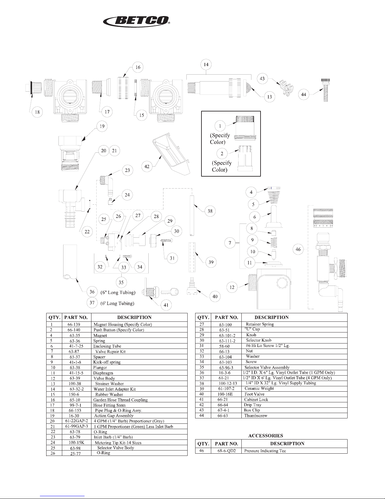
Caution: When servicing unit, be sure that replacement parts have been installed according to the drawing.
NOTE: THE MAXIMUM TEMPERATURE ALLOWABLE IS 150
°
F (65
°
C). THE MAXIMUM PRESSURE
ALLOWABLE IS 150 PSI (10 BAR).

PeroxiDraw™Dispenser
INSTALLATION INSTRUCTIONS
I-883 Pg. 4 of 6
05/05
Merchandise Returns
No Merchandise will be Returned for Credit Without BETCO’s Written Permission. Returned Merchandise Authorization Number is
Required in Advance of Return.
Product Warranty
Betco products are warranted against defective material and workmanship under normal use and service for
one year from the date of manufacture. This limited warranty does not apply to any products that have a
normal life shorter than one year or failure and damage caused by chemicals, corrosion, physical abuse, or
misapplication. Rubber and synthetic rubber parts such as “o”-rings, diaphragms, PVC tubing, and gaskets
are considered expendable and are not covered under warranty. This warranty is extended only to the
original buyer of BETCO products. If products are altered or repaired without prior approval of BETCO,
this warranty is void.
Defective units or parts should be returned to the factory with transportation prepaid. If inspection shows
them to be defective, they will be repaired or replaced without charge, F.O.B. factory. BETCO assumes no
liability for damages. Return merchandise authorization number must be granted in advance of returned
units for repair or replacement (See “Merchandise Returns” above).

PeroxiDraw™Dispenser
INSTALLATION INSTRUCTIONS
I-883 Pg. 5 of 6
05/05

PeroxiDraw™Dispenser
INSTALLATION INSTRUCTIONS
I-883 Pg. 6 of 6
05/05
Table of contents
Other BETCO Dispenser manuals