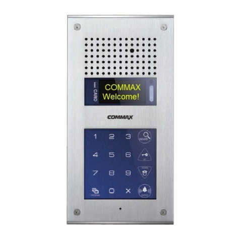
Beward DS06M(P) Instruction Manual

Installation User Manual
DS06M(P)
IP Video Door Station
Built-in IP Video Camera
Two-Way Audio
Electronic Motorized Lock Control
Multiaccessible User Operation
IP VIDEO SURVEILLANCE
net

Contents
IP Video Door Station DS06M(P) Installation User Manual
1
Contents
CHAPTER 1. SAFETY INSTRUCTIONS...........................................................................................2
CHAPTER 2. DESCRIPTION............................................................................................................4
2.1. KEY FEATURES......................................................................................................................5
2.2. PACKAGE CONTENTS .............................................................................................................5
CHAPTER 3. OVERVIEW.................................................................................................................6
3.1. DOOR STATION......................................................................................................................6
3.2. CONTROLLER ........................................................................................................................7
CHAPTER 4. DOOR STATION INSTALLATION............................................................................10
4.1. GENERAL INFORMATION .......................................................................................................10
4.2. INSTALLATION RECOMMENDATIONS.......................................................................................11
4.3. DOOR STATION MOUNTING...................................................................................................13
4.4. MEMORY CARD INSTALLATION ..............................................................................................21
4.5.WIRED CONNECTION TO A NETWORK ....................................................................................22
CHAPTER 5. WIRED CONNECTION SETTING.............................................................................23
5.1. DEFINING THE LOCAL NETWORK PARAMETERS FOR WIRED CONNECTION ...............................23
5.1.1. Defining the Local Network Parameters When Using a Dynamic IP Address..............27
5.2. CHANGING THE LOCAL NETWORK PARAMETERS ....................................................................30
5.3. ACCESSING THE DOOR STATION USING INTERNET EXPLORER ................................................34
5.4. ACCESSING THE DOOR STATION WEB INTERFACE..................................................................34
5.5. CONFIGURING DOOR STATION NETWORK SETTINGS THROUGH THE WEB INTERFACE...............39
5.6. RESTORING NETWORK SETTINGS OF PC TO THE PREVIOUS VALUES.......................................40
5.7. VERIFYING THE CONNECTION SETTINGS................................................................................43
CHAPTER 6. RECOMMENDATIONS ON SETTING AND OPERATION OF DS06M(P).................46
6.1. ACOUSTIC ECHO CANCELLATION ..........................................................................................46
6.2. SOUND GAIN AND VOLUME ADJUSTING..................................................................................47
APPENDICES.................................................................................................................................49
APPENDIX A. FACTORY DEFAULTS...............................................................................................49
APPENDIX B. GLOSSARY.............................................................................................................49

Chapter 1. Safety Instructions
IP Video Door Station DS06M(P) Installation User Manual
2
Before using the product.
This product complies with all safety rules. However, improper use of any electric device
can cause fires and severe damage. In order to avoid accidents, please read this Manual carefully
before you start using this door
ATTENTION!
Use accessories specified by the manufacturer only. Use of improper accessories may case device
breakdown.
Follow this Operation Manual.
Do not use or store the door station in severe environment:
Avoid extremely low and high temperatures (The operating temperature of this door
station is -40°~+50°).
Avoid prolonged exposure to direct sunlight, do not install near water and heat sources.
Do not install near electromagnetic transmitters
Avoid exposure to high vibration.
ATTENTION!
Contact out Service Center in case of malfunction.
In case of:
Smoke or strange smell coming from the door station.
Water or foreign matter getting inside the door station.
The door station getting damaged:
Do the following:
Unplug the power cord and disconnect all other cords from the door station.
Contact our Service Center. You can find our contact information on our website:
http://www.beward.ru/.

Chapter 1. Safety Instructions
IP Video Door Station DS06M(P) Installation User Manual
3
Transportation
Transport the door station carefully, using the original box and protective packing
Air flow
In order to avoid overheating, ensure that nothing is blocking the air circulation around the
door station!
Cleaning
Use a soft dry cloth to clean the surface of the device. To remove obstinate stains, apply a
small amount of detergent on the cloth, then wipe the surface dry
Do not use volatile solvents (alcohol-containing products, Benzene etc.) to avoid damaging
the door station housing.

Chapter 2. Description
IP Video Door Station DS06M(P) Installation User Manual
4
Chapter 2. Description
DS06M(P) IP Video Door Station is designed for organizing IP intercome systems based on
already existing local networks without using any additional equipment (e.g. separate internal
monitors). To start using the door station you only have to install the software from the disk and set
it up. Low cost, easy installation and remote access to the. This device is:
Low-cost
Easy to install
Remote Access Supported
Pic. 2.1
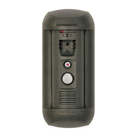
DS06M(P) has build-in microphone, speaker, video camera, Infrared LED and a call button,
as well as vandal-resistant housing. The device allows establishing video and audio connection
between the Guest and the Client, conducting surveillance of the nearby territory, control of other
devices that are connected to the door station (electronic locks, garage door openers, light
switches, alarm systems etc.) Infrared LED (with work distance up to 10 m) and the mechanical
infrared filter allow conducting video surveillance in low-light level environments. The device is
supported by modern network technologies, allowing it to be used a part of a complex IP
Surveilance system.
DS06M Door station is connected to the network via-T/100BASE-TX Ethernet interface. Its
power is supplied from a DC 12V power source. The device also supports PoE.
The device is even more reliable due to its SD card support that prevents loss of data in
case of network failures
2.1.1. Key Features

Chapter 2. Description
IP Video Door Station DS06M(P) Installation User Manual
5
Image sensor: 1.3 MP, CMOS 1/3'' SONY ExmorTM, Day/Night
Simultaneous encoding: H.264/H264, Н.264/MJPEG, MJPEG /MJPEG
Framerate: Up to 25 fps (all resolutions)
IR Illumination (distance up to 10 m) and a mechanical IR filter
4GB MicroSDHC memory card installed (up to 32GB supported)
Multistreaming: up to 10 unique streams (only one user can be in the two-way audio
mode at one time)
Built-in web server for viewing and adjusting settings
Built-in player for recorded videos
Build-in microphone and speaker
Power: DC 12 V, 0.5 A / PоE 802.3af Class 0 (for DS06MP only)
Temperature: -40°С~+50°С
Supported protocols: TCP/IP, SIP v.2.0, PPTP, HTTP, HTTPS, FTP, SMTP, DDNS,
DHCP, PPPoE, RTP, RTSP, UPnP, UDP, NTP, ONVIF v.2.41, Modbus TCP, Camdrive
ONVIF v.2.41 support
2.1.2. Package contents
DS06M(P) Door station
Bracket with mounting kit
Security screw with L- key
NC103 / NC103P / NC311P controller
RJ45-S01 (2 pcs.)
Terminal block
CD with software and documentation
ATTENTION!
Package contents and device specification are subject to change without notice

Chapter 3. Overview
IP Video Door Station DS06M(P) Installation User Manual
6
Chapter 3. Overview
3.1. Door Station
A door station front view is given below:
Pic. 3.1
1 –light sensor: a photoelectric cell that allows for automatic switching between Day and
Night modes .
2 –built-in microphone: allows the Client to receive sound from the surveillance area.
3 –IP camera: allows the Client to monitor the surveillance area.
4 –IR LED: the infrared light-emitting diodes used instead of standard electric lamps
provide video surveillance process at a low light level as well as at nighttime.
5 –call button: a call notification is sent to the Client when the Guest presses this button.
6 –built-in speaker: combined with the built-in microphone it provides a two-way audio
channel between the Client and the Guest.
7 –bracket frame: combined with a bracket plate it fixes the door station on the mounting
surface.

Chapter 3. Overview
IP Video Door Station DS06M(P) Installation User Manual
7
Pic. 3.2
8 –RJ45 socket: is used for connecting the door station to the NC103 / NC103P / NC311P
controller via a patch cable.
9 –reset button: press this button 3 times with intervals not less than 1 second during 10
seconds to set door station settings by default.
10 –memory card slot: is situated inside the door station housing, on the upper interface
board, from one side.
3.2. Controller
A door station controller is used for powering the door station, network connection,
processing the signal of door opening and signals of other devices that can be connected to the
door station.
A 1-channel or a 3-channel controller can be included in the DS06M(P) package contents.
There is an RJ45 socket (“ETHERNET”)on the front side of the door station controller,
which is used for connecting the controller to a router (Pic. 3.3, 3.4).
Pic. 3.3. Controller NC103 / NC103P

Chapter 3. Overview
IP Video Door Station DS06M(P) Installation User Manual
8
Pic. 3.4. Controller NC311P
The front side of the NC311P controller also has the following:
a light indicator of work state of the controller;
a “LINK” button which is used for setting interaction between the controller and the
door station;
NOTE!
For operation with the NC311P controller (in the DS06MP-3L package contents) it is obligatory to set
interaction between the controller and the door station. Press the “LINK”button on the controller and
then click [Connect] in the menu Config –Controller of the door station web user interface when
“NC311P”is chosen as a type of a controller (refer to Operation User Manual for details).
The interaction procedure takes about 1 minute from the moment of pressing the “LINK” button.
“DGU+” technological connector (not used in the current controller model).
Power over Ethernet (PoE) is provided by the NC103P or NC311P controller and a router
(or PoE injector) supported PоE 802.3af Class 0.
A rear view of the door station controller is shown on the Pictures 3.5, 3.6:
Pic. 3.5. Controller NC103 / NC103P
Pic. 3.6. Controller NC311P

Chapter 3. Overview
IP Video Door Station DS06M(P) Installation User Manual
9
1 –RJ45 socket (“ETHERNET”/“DOOR ST”)is used for connecting the NC103 / NC103P
/ NC311P controller to the door station via a patch cable. The patch cable should be made using
RJ45-S01 connectors from the package contents (see paragraph 4.5).
ATTENTION!
The patch cable must be connected to the door station via an RJ45 connector! It is impossible to connect
the door station using any other cable connector .
2 –terminal connector (ALARM OUT): is used for connecting a door lock or another
device controller. In case of connection to the 1-channel door station controller, NC103 or NC103P
(shown on the Picture 3.5), the signal opening the door outputs to the lock controller is transmitted
via «1A» and «1B»pins.
In case of the 3-channel NC311P controller , the signal opening the door outputs to the lock
controller is transmitted via «1A» and «1B»/«1С», «2A» and «2B»/«2С», «3A» and «3B»/«3С»
pins for the first, the second and the third channel accordingly (Pic. 3.6). The «A» and «B» pins are
normally open, and the «A» and «С» pins are normally closed.
The «G» and «12V» pins of the NC103 controller (without PoE support) are used for DC
12V power supplying of the door station. It is necessary to connect a power supply recommended
by BEWARD and the lock controller to these pins.
The «G» and «12V» pins of the NC103P / NC311P controller (with PoE support) are used
for powering the lock controller (several lock controllers) with DC 12V. In this case it is necessary
to connect only the lock controller to these pins.
ATTENTION!
Use only DC 12V power supplies recommended by BEWARD!
Power supplying using both PoE and the «G» and «12V» pins (for NC103P and NC311P controllers) at
one time is prohibited!
ATTENTION!
Maximum current rate provided by the NC103P, NC311P controllers for powering door locks and their
controllers is 500 mA. If this value is exceeded the device may malfunction or break. The device
breakdown caused by the exceeding of the maximum current rate is not covered by the warranty.

Chapter 4. Door Station Installation
IP Video Door Station DS06M(P) Installation User Manual
10
Chapter 4. Door Station Installation
4.1. General Information
The door station can be connected directly to a computer or via a router (a switch).
Pic. 4.1
The general instructions and installation recommendations are given below.

Chapter 4. Door Station Installation
IP Video Door Station DS06M(P) Installation User Manual
11
4.2. Installation Recommendations
This paragraph contains a short list of recommendations necessary for the correct
installation of DS06M(P).
IP Video Door Station DS06M is installed in the dry places on the surface of the inactive
leaf of exterior double doors or on the wall of the building. It is recommended to install the device
indoors (vestibules, entrance halls), avoiding the outside installation. It is also recommended to lay
cables in an ergonomic way.
Install the door station in a well-lighted area avoiding exposure of the camera lens to direct
sunlight. The mounting height must be convenient for the Guest to talk with the Client. It is
recommended to install the door station at height of about 1.5 m from the floor.
Then it is recommended to provide the uninterrupted power supply of router, door station,
electronic lock and its controller.
Recommendations for door station placement:
The operating temperature range is -40°С to +50°С.
Avoid exposure to direct sunlight and do not locate the door station near any heat
sources.
Incorrect installation may cause undesirable “blind spots
Do not locate the door station near any electrical appliances which can be
electromagnetic transmitters.
When installing the door station, make sure the cables are laid in a safe and ergonomic
way..
Avoid unstable installation, which may allow exposure to high vibration. This may reduce
motion detection performance and image quality in general.
The view direction should be clearly determined at the moment of the door station
installation.

Chapter 4. Door Station Installation
IP Video Door Station DS06M(P) Installation User Manual
12
Recommendations for twisted pair cable routing:
In corridors, it is advisable to install electric and feeble-current cables in different
conduits that are disposed on different walls.
Twisted pair and electric cables can be installed in the same conduit using different
sections of the cable that have solid longitudinal partitions with at least 0.25 h of fire
resistance, which are made of non-combustible material and should be positioned in
work areas at distance of 15 meters maximum if the electrical power does not exceed 5
kW.
Electric and feeble-current cables should be placed in parallel to each other at distance
of at least 50 mm in different conduits or different sections of conduit. If the electric field
strength from the electric cables exceeds 3 V/m, you should increase the distance
between the electric and feeble-current cables or reduce the electromagnetic noise.
Twisted pair and electric cables should cross each other at right angles.
Unshielded twisted pair cables should be located at distance of at least 125 mm from
fluorescent gas-discharge lamps or from other high-voltage discharge devices.
Unshielded twisted pair cables should be located at distance of at least 1.5 meters from
electromagnetic interference sources that produce electric field strength exceeding 3
V/m.
Switchboards with pinned unshielded twisted pair cables should be located at distance
of at least 3 meters from electromagnetic interference sources that produce electric field
strength exceeding 3 V/m.
Cable runs should be arranged between the points of connection such a way so the
overall cable path length is as short as possible.
Minimum cable bending radius is four times the cable diameter (or 1 inch=2.5 cm). It is
also acceptable to install the cable so that the cable bending radius is 2 inches (5 cm).
Maximum length of the entire segment is 100 meters.

Chapter 4. Door Station Installation
IP Video Door Station DS06M(P) Installation User Manual
13
4.3. Door Station Mounting
Follow the steps below:
Step 1: take the bracket plate (Pic. 4.2). Choose the right height of mounting above the
floor. The recommended height is about 1.5 m.
Step 2: mark the holes on the mounting surface using the bracket plate as a template. Drill
the holes.
Pic. 4.2
Step 3: insert plastic wall dowels in the holes and fix the bracket plate using four screws.
The heads of some other screws you use (not from the package contents) must be not higher than
2.5 mm and not bigger than 9 mm in diameter.
Step 4: there are hidden and open ways of cabling:
for hidden cabling drill a hole for twisted pair cable output at the distance of 25 mm from
the bottom of the bracket plate. Leave 110 mm of the cable outside.
for open cabling fix a cable channel on the wall so that the distance between the
channel and the bottom of the bracket plate would be 36 mm. Leave 110 mm of the
cable outside (Pic. 4.3).

Chapter 4. Door Station Installation
IP Video Door Station DS06M(P) Installation User Manual
14
Pic. 4.3
Step 5: before attaching a connector to the twisted pair cable put a rubber seal from the
package contents on it to make to seal the connection area (Pic. 4.4).
Pic. 4.4
Step 6: attach the RJ45-S01 connector from the package contents to the twisted pair cable
using a crimping tool. For more information on how to crimp a twisted pair cable go to the
paragraph 4.5.
ATTENTION!

Chapter 4. Door Station Installation
IP Video Door Station DS06M(P) Installation User Manual
15
The patch cable must have the RJ45-S01 connector at the end connected to the door station! It is
impossible to connect the door station using a cable connector of some other form.
The twisted pair cable (5еUTP/FTP) connected the door station with its controller should
be wired the same at both ends (“straight-through”form).
ATTENTION!
The device breakdown caused by wiring the cable in different manner is not covered by the warranty.
Use the cable of the minimal possible length to connect the door station and its controller. Proper
operation of the device cannot be guaranteed in case of using of the 10 m cable and more.
Step 7: connect the crimped cable to the door station, sealing the connection area, and put
it in the bracket frame. Rotate the door station in the frame to set the appropriate view direction of
the built-in IP camera. Place a excess part of the cable as it is shown on the picture below:
Pic. 4.5
Step 8: specific notches of the bracket frame and the door station (Pic. 4.6) allow the
station to be fixed well and prevent loose rotation during operation.

Chapter 4. Door Station Installation
IP Video Door Station DS06M(P) Installation User Manual
16
Pic. 4.6
A view direction of the built-in IP-camera must be clearly determined at the moment of the
door station installation (rotating angles are ±45° from the middle position).
Step 9: apply the door station inserted in the bracket frame to the bracket plate fixed on the
wall. Then move them down with force up to the stop. The bracket frame should completely cover
the bracket plate, and there should not be any space between the frame and the wall.
Step 10: ensure that the bracket is fixed well. In case of a gap between the bracket frame
and the door station, check the joints of the fixation notches. There must be no space between
parts if the notches fit each other. If they don’t, change door station’s position inside the frame to fit
it better (Pic. 4.7).
a) Correct installation. There is no gap. b) There is a gap between door station and bracket.
Pic. 4.7
Step 11: fix the door station inside the bracket frame using the hexagonal socket screw and
L-key from the package contents. To do so push the bracket frame down and simultaneously
tighten the secret screw up (Pic. 4.8).

Chapter 4. Door Station Installation
IP Video Door Station DS06M(P) Installation User Manual
17
Pic. 4.8
Step 12: attach the RJ45 connector to the other end of twisted pair cable using a crimping
tool as it described in the paragraph 4.5.
ATTENTION!
The twisted pair cable (5еUTP/FTP) connected the door station with its controller should have the same
wire arrangement on both ends (“straight-through” form). The device breakdown caused by wiring the
cable in different manner is not covered by the warranty.
Step 13: connect the crimped cable to the RJ45 socket (ETHERNET) of the NC103 /
NC103P / NC311P controller (Pic. 3.5, 3.6).
Step 14: connect the door lock controller to the terminal block of the door station controller.
The recommended connection schemes are given below.
NOTE!
The NC103P controller is shown on the schemes 2, 3 (Pic. 4.10, 4.11). The same schemes can be also
used in case of connection of the NC311P controller.

Chapter 4. Door Station Installation
IP Video Door Station DS06M(P) Installation User Manual
18
1. Without PoE (DS06M package contents):
Pic. 4.9
NOTE!
There are two main reasons why it is recommended to use separate power supply units for the door and
the door station when using an electronic lock.
The first reason is that the current, powering the door station, has a value comparable to that of the
current powering the electronic lock. So the electronic lock power supply unit runs out quickly, powering
the door station.
The second reason is that there is a risk of the door opening in case of a short circuit of the external
power supply line (door station side).
ATTENTION!
Use only DC 12V power supplies recommended by BEWARD! For recommendations please visit our
website (www.beward.net).
It needs to highlight that the maximum current rate provided by the power source for supplying of the
door station, door lock and other equipment should not be exceeded.

Chapter 4. Door Station Installation
IP Video Door Station DS06M(P) Installation User Manual
19
2. With PoE (DS06MP package contents):
Pic. 4.10
In this case the door lock and its controller are supplied with power by an external 12V
power source, but the door station use PoE supplying.
ATTENTION!
Power supplying via both PoE and the «G» and «12V» pins (for NC103P and NC311P controllers) at one
time is PROHIBITED!
Table of contents
Other Beward Intercom System manuals
Popular Intercom System manuals by other brands
Mobotix
Mobotix T24S Manual for operation and installation
urmet domus
urmet domus VOG 5 User handbook
Gewiss
Gewiss Chorus ANTAS GW19061 user manual
Radio Shack
Radio Shack FM Telephone Line Intercom owner's manual
CyberData
CyberData 11186 Operation guide
SECO-LARM
SECO-LARM Enforcer DP-121Q installation manual
