ChinaPST PST-VDA-R2 User manual

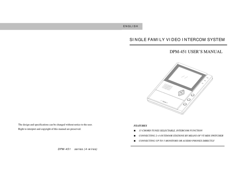
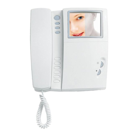
Apartment video door phone
1

In Multi-apartment System
2
Contents
Preface ...................................................................................................1
1 Parameter ...........................................................................................2
2 Instruction ............................................................................................2
2.1 Outdoor Station ................................................................................4
2.2 Indoor Unit ........................................................................................7
2.3 Distributor..........................................................................................9
2.4 Power Supply .................................................................................10
2.5 Multi-entrance Controller ................................................................10
3. Wiring Diagram .................................................................................11
4. System Setting .................................................................................12
4.1 Setting ISN Code ............................................................................12
4.2 Setting Room Number ....................................................................15
4.3 Setting Building Number and Unit Number .....................................15
4.4 Setting of Gate Entry Station ..........................................................17
4.5 Setting Network Cable Converter ...................................................17
4.6 Set Security Zone ...........................................................................18
5. Setting Unlock Password .................................................................19
6. ID/ IC Card ........................................................................................19
7. Remote Control ................................................................................20
8. System Instructions ..........................................................................23
9. Gate Entry Station ............................................................................24
10. Guard Station .................................................................................25
11. Accessories .....................................................................................26
12. Warning ..........................................................................................28

In Multi-apartment System
3
Preface
Thank you for using our products. Hope our products and services
can bring convenience and happiness to your life.
This is video door phone for villa, single family house, single
apartment.
1) Connect with CAT 5e ( UTP—Unshielded Twisted Pair )
2) CAT 5e transmit audio signal, RS487 communication, video
signal.
3) Access control function: ID/ IC cards
4) Support to connect electric lock
To obtain the best performance and ensure years of trouble-free
use before operating it, please read this instruction manual
carefully.

In Multi-apartment System
4
1. Parameter
Outdoor
Station
Installation
Flush-mount
Voltage
DC12V±10% (Working)
Current
≤650mA (Working); ≤150mA (Standby)
Indoor Unit
Installation
Wall-mount
Voltage
DC18V±10% (Working)
Current
≤ 300mA (Working); ≤20mA (Standby)
Wiring
requirements
Connection: CAT5e / Cat6 Cable ( normal network cable )
Power line : RVV2 * 0.75
Lock line : RVV2 * 0.75
2 The Instruction
2.1 Outdoor Station
Figure 1
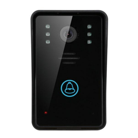
①Card Reader : ID card / key Fob / Password
②Touch Button : Press to call a household
③Microphone: Talk
④Night Vision: 6 IR lights /white LED lights
⑤Speaker: Two protective net behind the hole
⑥Camera: 1/4” 650TVL CMOS Camera , 98° wide angle

In Multi-apartment System
5
Features:
※Waterproof: IP54
※Aluminium alloy and acrylic panel
※Unlock by ID cards & password
※English Voice Prompt Functioned
※2-way audio and video intercom
※Suitable for Multi-apartment
※Suitable for Digital system
※Receive call from Guard Station and Indoor Unit
※One Outdoor Station is compatible to 1024 rooms at maximum.
※CAT5e/CAT6 network cable for connection between outdoor unit to indoor
unit.
Figure 2 The Outdoor Station’s Front view, Side view, Back view
※Green & grey wire: lock line
※RJ45: Connection for Network Cable ( CAT5e )
Wire

In Multi-apartment System
6
Noted:
(1) Do not shake, collide, smash, punch the device;
(2) Do not install the Outdoor Station in the following places:
※Under long-time sunshine;
※40 Fahrenheit;
※Under long-time snow and frost;
※Dusty;
(3) When electrified, if there is any unexpected situation happened,
please cut off power immediately until the fault is removed.
(4) If it is in abnormal status, cut off power first. And check it carefully.
Any malfunctioning fault, please contact with supplier and do not try to
repair by your own.
(5)Do not wash and fold card reader.
Figure 3 The Outdoor Station of Installation
Figure 3 The diagram of Installation Outdoor Station

In Multi-apartment System
7
Installation requirements
(1) Match the fix hole in the wall and the fixing box. If the outdoor station
is embedded in the wall, in order to prevent the expansion of cement,
please make the hole in wall or door is bigger( 5mm) than the box.
(2) Put the bottom box fixed in the hole of the door or wall.
(3) Connected with the network cable.
(4) Fix the outdoor station to the installation bottom box with a screw.
Notice
(1) Applied System: Analog, and TCP/IP System
(2) Network Interface : RJ 45 Interface
(3) Ambient Temperature: -43.7℉~ 133℉
(4) Ambient Humidity : 45%~95%
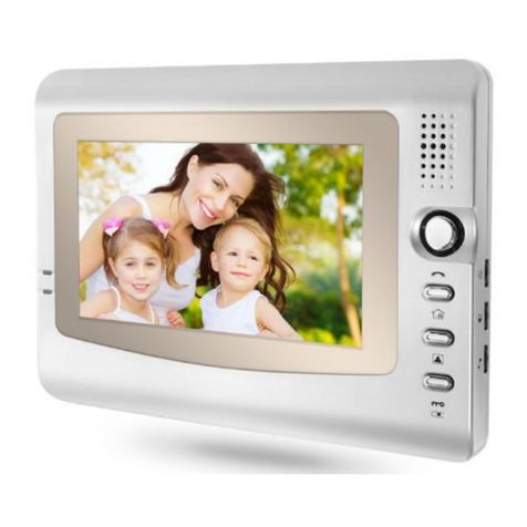
2.2 Indoor Unit
7” LCD screen
:Monitor key
:Unlock Door

In Multi-apartment System
8
:Send the information to the Guard Station
: ( ) Call Guard Station button
: Answer call
Operation introduction
A. One Outdoor Station is compatible to 4 indoor units at maximum.
When calling for indoor unit, all the indoor unit ring at the same time. The
others stop ringing after picking up one of the indoor unit.
B. When indoor unit is called, it will show images on the screen. Press
“Answer call” , confirm it and press to unlock Door . ( To unlock
the door, please press first, then press )
C. When the indoor unit is called, it will stop ringing in 90 seconds
without answering.
D. When in standby mode, press “ Monitor key ” to monitor
outside.
And stop automatically in 90 seconds .
Adjust the Color & Brightness
A. Under normal state, press “Monitor” button and then “Answer ” button
to enter into adjustment of screen.
B. "Monitor”: Home key; Contrast adjustment, Brightness adjustment.
C. “Answer ” button”: minus; “Unlock Door” button: add.
D. Press “Monitor” button to adjust brightness. “Answer” button
represents minus

In Multi-apartment System
9
brightness; “Unlock Door” button represents add brightness.
Failure analysis and troubleshooting
Failure
Inspection object
Troubleshooting
Can not call & be
called
Check whether the connecti
on of indoor units’ power
lines is good
Connect the power lines
correctly to make the light’s
on
Not ring after
being called
Check the speaker, music
chip and peripheral circuit
Replace music chip
The screen
doesn’t work
Check the control module
and circuit
Correctly connect the power
lines , or replace the other
indoor units
Can be called,
but cannot
Check whether microphone
is damaged or poor contact
Replace microphone
2.3 Distributor
Model: 4-ports Distributor
①:18V, connect to Power Supply (Red for positive electrode, black for
negative electrode)

In Multi-apartment System
10
②:US1, connect to indoor unit NO.1
③:US2, connect to indoor unit NO.2
④:US3, connect to indoor unit NO.3
⑤:US4, connect to indoor unit NO.4
⑥:Output, connect to the next distributor.
⑦:Input , connect to outdoor station.
※Do not open the distributor without the presence of professionals.
2.4 Power supply
Model: Power supply
Power supply: supplied power for outdoor station, indoor unit, distributor,
EML, etc.
※Input: 220V
※Please consult a professional before connecting.
2.5 Multi-entrance Controller
(1) Working Principle: Convey calling information (RS 485
communication, Audio & video) to the indoor unit and control outdoor
stations.
(2) Authority:

In Multi-apartment System
11
In calling : The outdoor stations can not make a call at the same time.
When a outdoor station is calling, the others is locked.
(3) Interface: Connect No.1 interface to the main outdoor station.
Please see page 27and Figure 12.
3. Wiring Diagram
User notes: please use the good quality network cable and power line to make
sure the best performance and ensure years of trouble-free use before
operating it.
Figure 4 The wiring of Multi-apartment system ( Non networking )
CAT5e Cable ( 8-core )
Power / Lock Cable:
RVV: 2*0.75mm
Remark:
1. Each power supply for distributor &
indoor unit can connect with 3-4
distributors ( 12-16 indoor units )
2. Distributor can be divided into 2 types:
4-port and 6-port.
3. Main wiring is used CAT5e cable for
connection, which is applied in series
connection while the power core is
applied in parallel connection.
4. Power supply: outdoor station: DC12V
distributors & indoor units: DC18V.

In Multi-apartment System
12
Remark:
(1) Suitable for one building.
(2) If there are more than one building managed by management center,
please see Figure 9, Page 14.
(3) Please connect power supply to 220V( Alternating Current/ AC ).

13
4. System Setting
4.1 Setting ISN Code
3 buttons “HIGH”, “CEN”, “LOW” on the distributor. Press different button, means
different code.
4.1.1 Switch on outdoor station, press “ HIGH” button and hold on about 5s. LED
light flashes 2 times and then releases it. It is in decoding state.
4.1.2 Press “ HIGH” , the light flashes 1 time, which refers to “hundred” digit.
4.1.3 Press “CEN” button, the light flashes 1 time, which refers to “ten “digit.
4.1.4 Press “LOW” button, the light flashes 1 time, which refers to “single” digit.
4.1.5 After setting the code, wait for 10s. The power’s light will be on for 5s to
represent the setting is completed.
Set the code as 401:
A. Press “ HIGH” for 4 times, the power’s light flashes.
( The hundred digit is 4 )
B. Do not press “CEN” button (The ten digit is 0)
C. Press “LOW” button 1 time, the power’s light flashes.
(The single digit is 1.)
D. Wait for about 10 seconds. When the light is on for 5 seconds, the operation is
completed.

14
4-Port Distributor ISN Code Chart:
HIGH
CEN
LOW
ISN Code
of
Distributor
Weight
Weight
×4
ISN Code of indoor unit
US1
US2
US3
US4
000
0
0× 4
000
001
002
003
001
1
1× 4
004
005
006
007
002
2
2× 4
008
009
010
011
003
3
3× 4
012
013
014
015
004
4
4× 4
016
017
018
019
005
5
5× 4
020
021
022
023
006
6
6× 4
024
025
026
027
007
7
7× 4
028
029
030
031
008
8
8× 4
032
033
034
035
009
9
9× 4
036
037
038
039
010
10
10× 4
040
041
042
043
011
11
11× 4
044
045
046
047
012
12
12× 4
048
049
050
051
013
13
13× 4
052
053
054
055
014
14
14× 4
056
057
058
059
015
5
15× 4
060
061
062
063
016
16
16× 4
064
065
066
067
017
17
17× 4
068
069
070
071
…
…
…
….
…
…
…
…
No press on
LOW key
One Press on
LOW key
Two Press on
LOW key
3 Press on
LOW key
Four Press on
LOW key
Five Press on
LOW key
Six Press on
LOW key
7 Press on
LOW key
8 Press on
LOW key
9 Press on
LOW key
1 Press on
CEN key
1 on LOW
1 on CEN
2 on LOW
1 on CEN
3 on LOW
1 on CEN
4 on LOW
1 on CEN
5 on LOW
1 on CEN
6 on LOW
1 on CEN
7 on LOW
1 on CEN

15
6-Port Distributor ISN Code Chart:
HIGH
CEN
LOW
ISN
Code
Weight
Weight
×4
ISN Code of indoor unit
US1
US2
US3
US4
US5
US6
000
0
0*8
000
001
002
003
004
005
001
1
1*8
008
009
010
011
012
013
002
2
2*8
016
017
018
019
020
021
003
3
3*8
024
025
026
027
028
029
004
4
4*8
032
033
034
035
036
037
005
5
5*8
040
041
042
043
044
045
006
6
6*8
048
049
050
051
052
053
007
7
7*8
056
057
058
059
060
061
008
8
8*8
064
065
066
067
068
069
009
9
9*8
072
073
074
075
076
077
010
10
10*8
080
081
082
083
084
085
011
11
11*8
088
089
090
091
092
093
012
12
12*8
096
097
098
099
100
101
013
13
13*8
104
105
106
107
108
109
014
14
14*8
112
113
114
115
116
117
…
…
…
….
…
…
…
…
No press on
LOW key
One Press on
LOW key
Two Press on
LOW key
3 Press on
LOW key
Four Press on
LOW key
Five Press on
LOW key
Six Press on
LOW key
7 Press on
LOW key
8 Press on
LOW key
9 Press on
LOW key
1 Press on
CEN key
1 on LOW
1 on CEN
2 on LOW
1 on CEN
3 on LOW
1 on CEN
4 on LOW
1 on CEN

16
4.2 Setting Room Number
This process is operated at Outdoor Station.
(1) Set ISN code of each indoor unit according to the < 4-Port Distributor ISN Code
Chart > and < 6-Port Distributor ISN Code Chart >.
(2) Press “ ##923132008 ” continuously on Outdoor Station’s keyboard, then the
display shows “ _001 ”
(3) Press ISN code , then press “ # ” to confirm.
(4) The screen shows dead number “FFFF”. (If it shows other four numbers, this
outdoor station has already been encoded.)
(5) Change the room number, enter 4-digit number.
(e.g. Room 301 → entering “0301”.)
(6) Press “ # ” to confirm the room number. Then the screen shows the next ISN
code. Repeat the above steps to continue.
Press “ * ” to log out or it will log out in 10s automatically.
(7) Press “ 8 ” represents “Number Up” to jump over to find the specific room
number,when setting ISN code ; press “9” represents “Number Down”. (“000” is
the first ISN code of the Outdoor Station.)
4.3 Setting Building Number and Unit Number
※This process is operated on the Network Cable Converter.
※There are 4 buttons on the Network Cable Converter, “ +1000 ” “ +100 ”

17
“ +10 ” “ +1”.
“ +1000 ”“ +100 ” : the Building No; “ +10 ” “ +1”: the Unit No.
Setting as below:
(1) Cut the power off.
(2) Keep pressing “ +1000 ” button and then switch on the Network Cable
Converter;
(3) Release the button when the green light is on,
(4) Effective setting:
press a button once and the light flashes once.
the light flashes in seconds after setting. It will turn off.
(5) Pressing on button “ +1000 ” once represents 1000; pressing on “ +1000 ”
button twice represents 2,000.
Examples are as follows:
A. NO.1 Unit, 1 Building :
Press “+1” button once and “+100” once. Wait for 5 seconds after pressing. The
green light is on, that means the setting is completed.
B. NO.33 Unit, 21 Building :
Press “+1000” twice, press “+100” once, press “+10” 3 times and press “+1” 3
times. Waiting for 5 seconds after pressing. The green light is on, that means the
setting is completed.

18
4.4 Setting of Gate Entry Station
(1) Enter “ ##92702689 ” on the keyboard to get into the setting process;
(2) Enter 4-digit number (The range ISN code of Gate Entry Station are 0001~9999.
Enter “ 0001 ”: the NO.1 Gate Entry Station in community.)
(3) Press “#” to exit the process when operation completed.
Noted: The ISN code of Gate Entry Station cannot be set as “0000”. Different Gate
Entry Station cannot has the same ISN code.
4.5 Setting Network Cable Converter
Keep pressing the “1000+” button for 3 seconds when the Network Cable Converter
is electrified. The light is on and release the button.
Examples are as follows:
“NO.1111 Building”
A. Press “1000+” button once → The LED light flashes once.
B. Press “100+” button once → The LED light flashes once.
C. Press “10+” button once → The LED light flashes once.
D. Press “1+” button once → The LED light flashes once.
Wait for about 10 seconds. The LED light is on and the operation completed.
4.6 Set Security Zone of Indoor Unit
(1) There are 8 security zones of an indoor unit and 4 LED lights which stand for
security zones. If the lights are on, there are abnormal conditions happened in 1, 2,

19
3, 4 security zone. If these lights are flashing, there are abnormal conditions
happened in 5, 6, 7, 8 security zone.
(2) A. NO.1.2.3.4 Security zone: Connect to emergency button, smoke sensor. You
do not need to set up and they are in armed status in 24 hours. Trigger and give an
alarm.
B. NO.5.6.7.8 Security zone: Connect to EML (electromagnetic lock), IR
Sensor. You do not need to set up into armed status. They work in 30
seconds after setting.
(3) Connection of Security Zones:
Security Zone NO.
1
2
3
4
5
Color of Wire
Red
Blue
Black
Yellow
White
Security Zone NO.
6
7
8
Ground Wire
Color of Wire
Green
Grey
Brown
Orange
(4) Setting armed status-- Special for model: Q8
Model: Q8 is 4.3 inch indoor unit
A. In armed status: when it is not calling, press “ Armed ” button →into armed status,
and four security lights are on.
B. In alarm status : when it is not calling, press “ Unarmed ” button →into unarmed
status, and security lights are off.
5. Setting Unlock Password
Set Unlock Password in outdoor station.

20
(1) Call indoor unit from the outdoor station → pick up phone
(2) When it is calling, press “ Unlock ” button → hold for 5 seconds → it will show
“ L_ _ _ ” on the screen in outdoor station → enter unlock password.
(3) After entering, the outdoor station will sound “Di-Di-” to indicate the successful
setting.
(4) Operation of entering unlock password
press “ #” → enter “ Room Number ” → enter “ #” → enter unlock password (If the
operation is correct, it will show “ OPEN ”; If it is not, it will show “ Err5 ” and exit
setting.)
6. ID/ IC Card
6.1 Initialization Setting: Set two administrator cards.
Turn card reader off → put “ JUMP1 ” on position 12. → turn card reader on → the
code is “1234” and the green light is on. → Then swipe the 1st card (This card is
usually defined as “ The Add Card ”) until the red light is on. → Swipe the 2nd card
(This card is usually defined as “The Delete Card”) until it sounds “Bi-Bi-” → put
“ JUMP1 ” on position 13 and completing the setting.
JMP1
Normal
Initialization and management card setting
JMP2
Unlock time setting: 6s
Unlock time setting: 1s
P3
Connect infrared sensor
Table of contents
Other ChinaPST Intercom System manuals
