2
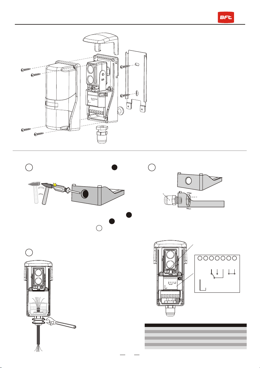
Mounting the Sensor:
Wiring:
Wiring connection:
1. Unscrew the4 screws andremove the
cover.
2. Loosen thecaptive screw tofree the
sensor from themounting plate.
3. Using theincluded screws, mountthe
mounting plate tothe wall.
4. Use thebreakout and cablegland at the
bottom of thesensor to runthe wires.
5. Remove theterminal block usinglong-
nose pliers andwire the unitaccording
to the wiringdiagram above.
6. Hang thesensor back onto the plate,
and use thecaptive screw tosecure it in
place.
7. Re-attach thecover, anduse the
Included small screwsto secure it.
8. Attachthe hood tothe top ofthe sensor.
2. Then screwthe knob withthe nut till
them fixed.
A
1
3
1. Please usescrewdriver & hammerto break
plastic pack downand remove pack . Then
insert the cablegland into the empty hole.
(See diagram 2)
a. Insert thecable wires into
the cable gland.
b. Connect thelead wires to the
proper position of terminal
block.
c. Use spanner to tight thecable
gland clockwise to the end
(the most tightness).
A
A
A
A
2
A
Break down &remove plastic pack
Finish the wiringconnection:
Install the cablegland
Knob
Nut
Clockwise
1234567
12-30VDC/AC 60 Hz
NC
NC
NO
COM
TP1
TP2
Non polarity
PWR/
Beam Alignment
LED Indicator
PWR/
Beam Alignment
LED Indicator
Additional function:
TP1/TP2 - Tamper Switches,
can be connected with control
panel or siren as burglar alarm.
Additional function:
TP1/TP2 - Tamper Switches,
can be connected with control
panel or siren as burglar alarm.
1234567
12-30V DC/AC 60 Hz
NC
NC
NO
COM
TP1
TP2
Non polarity
1234567
12-30V DC/AC 60 Hz
NC
NC
NO
COM
TP1
TP2
Non polarity
MANUAL Model No.: KIRPOLAPHOT001
CONNECTION GUIDE FOR BFT CONTROL BOARDS
TERMINAL DESCRIPTION LIBRA QSCD RIGEL 4 RIGEL 5 THALIA THALIA UL
1 11 12 15 20 50 50
12-30V DC/AC 60 Hz
212 13 16 21 51 51
12-30V DC/AC 60 Hz
315 21 32 52 70 70
Relay, Normally Closed
4Relay, Normally Open
518 24 33 55 79 72
Relay, Common
6Tamper Switch, N.C.
7Tamper Switch, COM


