SK2000 STEPPER
8
ASSEMBLY INSTRUCTIONS
1. The unit is heavy. Two people are required to
safely assemble the unit. Take the unit out of its
box and make sure that all of the pieces are there,
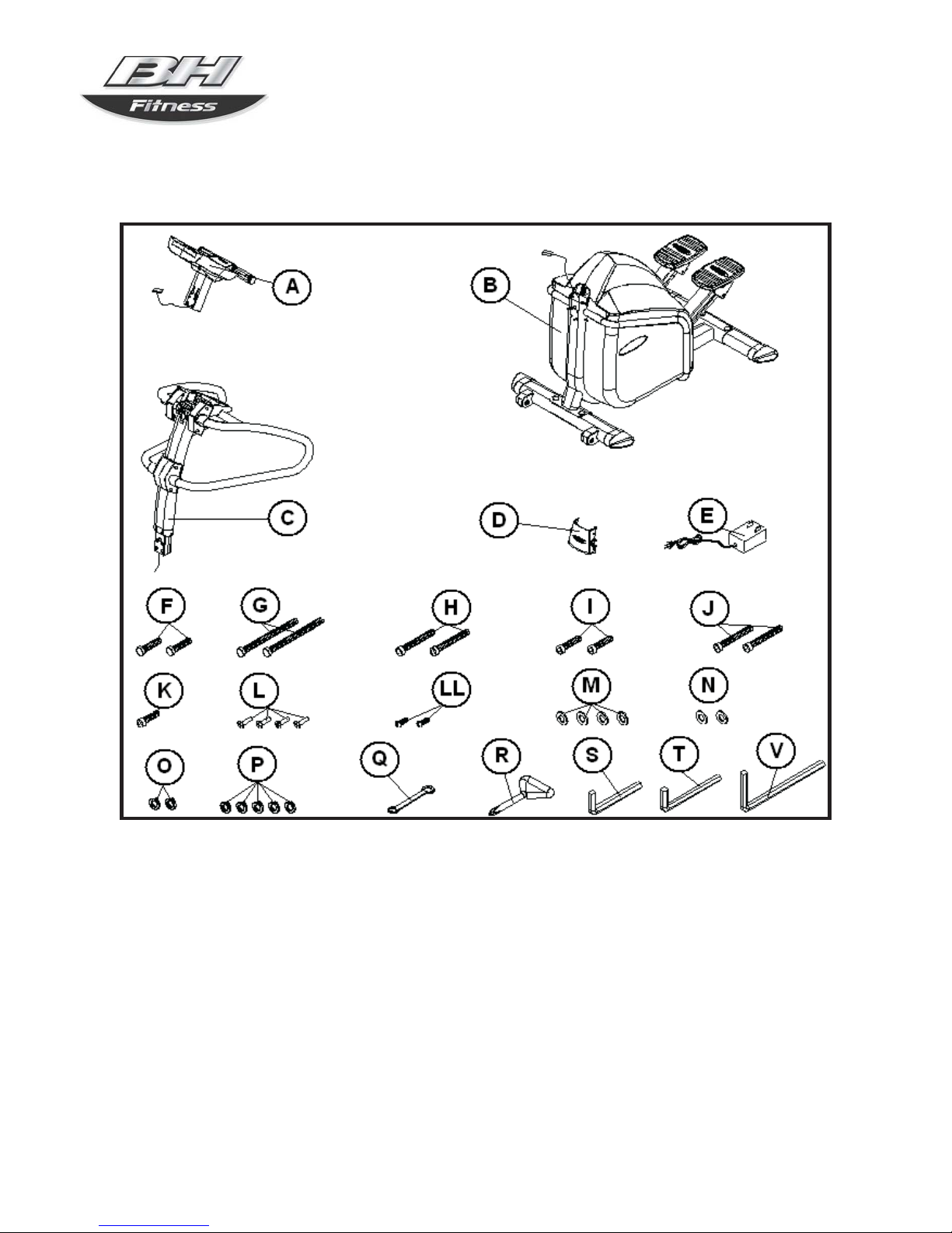
Fig 1:
A) - Monitor
B) - Main body
C) - Han drail Han dlebar
D) - Front trim cover.
E) - The adapter
F) - Screw M-10x 30 Quantity 2
G) - M-10x80 Quantity 2Screw
H) - Allen M-6x65 Quantity 2Screw
I) - Allen M-8x25 Quantity 2Screw
J) - Allen M-8x55 Quantity 2Screw
K) - Allen M-10x25 Quantity 1Screw
L) - Screw Phillips M-5x15 Quantity 4
LL) - Screw Phillips M-4x15 Quantity 2
M) - Flat washer M-10 Quantity 4
N) - Flat M-8 Quantity 2washer
O) - Grower washer M-8 Quantity 2
P) - Grower washer M-10 Quantity 5
Q) - Combination spanner
R) - Star driver .spanner
S) - Allen key 5mm.
T) - Allen key 6mm.
V) - Allen key 8mm.
2. ATTACHING HANDRAIL HANDLEBAR
Bring the handrail handlebar (C) up to boss on the
main body (B), Fig. 2
Take terminal (1) on Body (B) and, with the help of
the cord (20-22) already inserted inside the
handlebar tube, pull Terminal 1 in through the tube
(C) bringing it out through the top.
Now slip the handlebar tube over the boss on the
main body (B) in the direction of the arrow, as shown
in Fig. 2, making sure not to snag any of the cables.
Next, take screw (K) along with the washer (P), Fig.
2, and secure. Then take screws (F) along with their
washers (P) and flat washers (M) and secure. Finally,
take screws (G) along with the washers (P) and flat
washers (M) and tighten securely, including those
fitted previously.
3. FITTING THE MONITOR
Take hold of the monitor (A) and bring it up to the
handlebar tube (C), as shown in Fig. 3. Connect the
terminals (1), sticking up out of the top of the tube
(C), with terminal (21) coming down from the bottom
of the monitor (A), Fig.3, and insert the tube on the
monitor into the boss on the main body (B) in the
direction of the arrow, making sure not to snag any of
the cables.
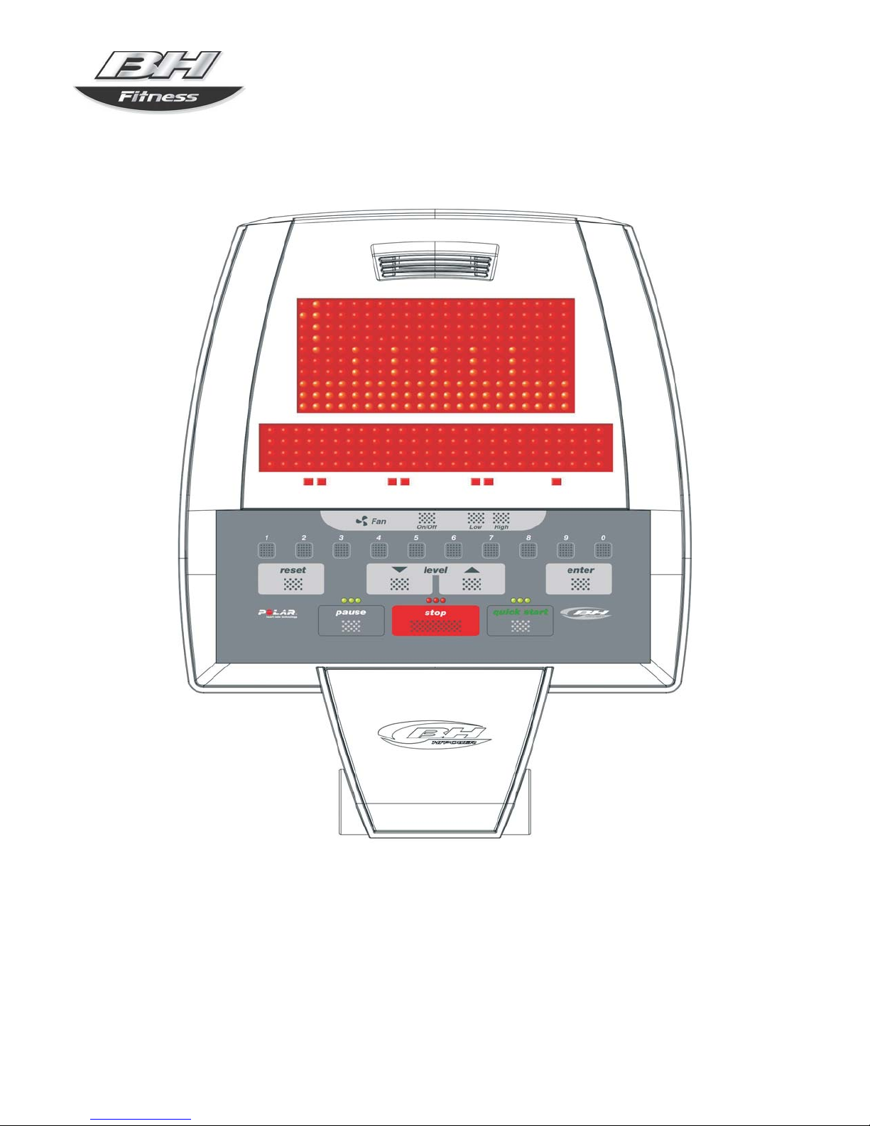
Check that the cables are connected correctly by
pushing the foot pedals in order to spin the dynamo until
the monitor starts to operate.
Once you have checked that it works, insert screws (H).
Insert washer (N) with screw (J), Fig.3.
Then take screws (I), along with the washers (O), and
tighten as shown in Fig 3A.
Line the handlebar up with the machine and tighten the
screws (H) and (J) securely.
4. FITTING THE FRONT TRIM COVER
Place the trim cover (D) on the front part of the unit,
Fig.3. Next, take screws (L) and secure the cover by
tightening the screws.
5. FITTING THE TOP TRIM COVERS
NOTE: The top trim covers are preassembled onto
the handlebars (C). They are placed into the correct
position and screwed on.
Move the top trim covers up to the handlebar (C)
tube, Fig. 3. Take screws (LL) and screw them on.
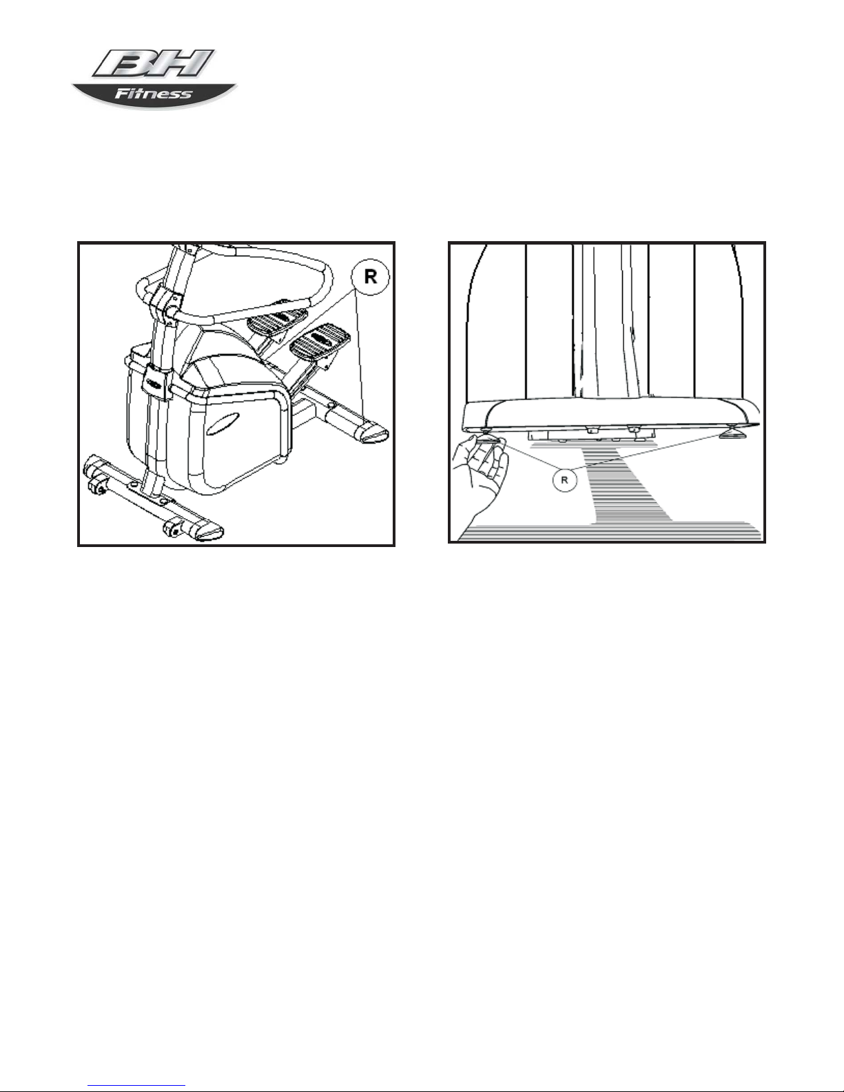
6. LEVELLING
Figure 5. When doing exercise, make sure that the
unit sits flat on the floor and that it is level. Screw the
adjustable support blocks (R) up or down.
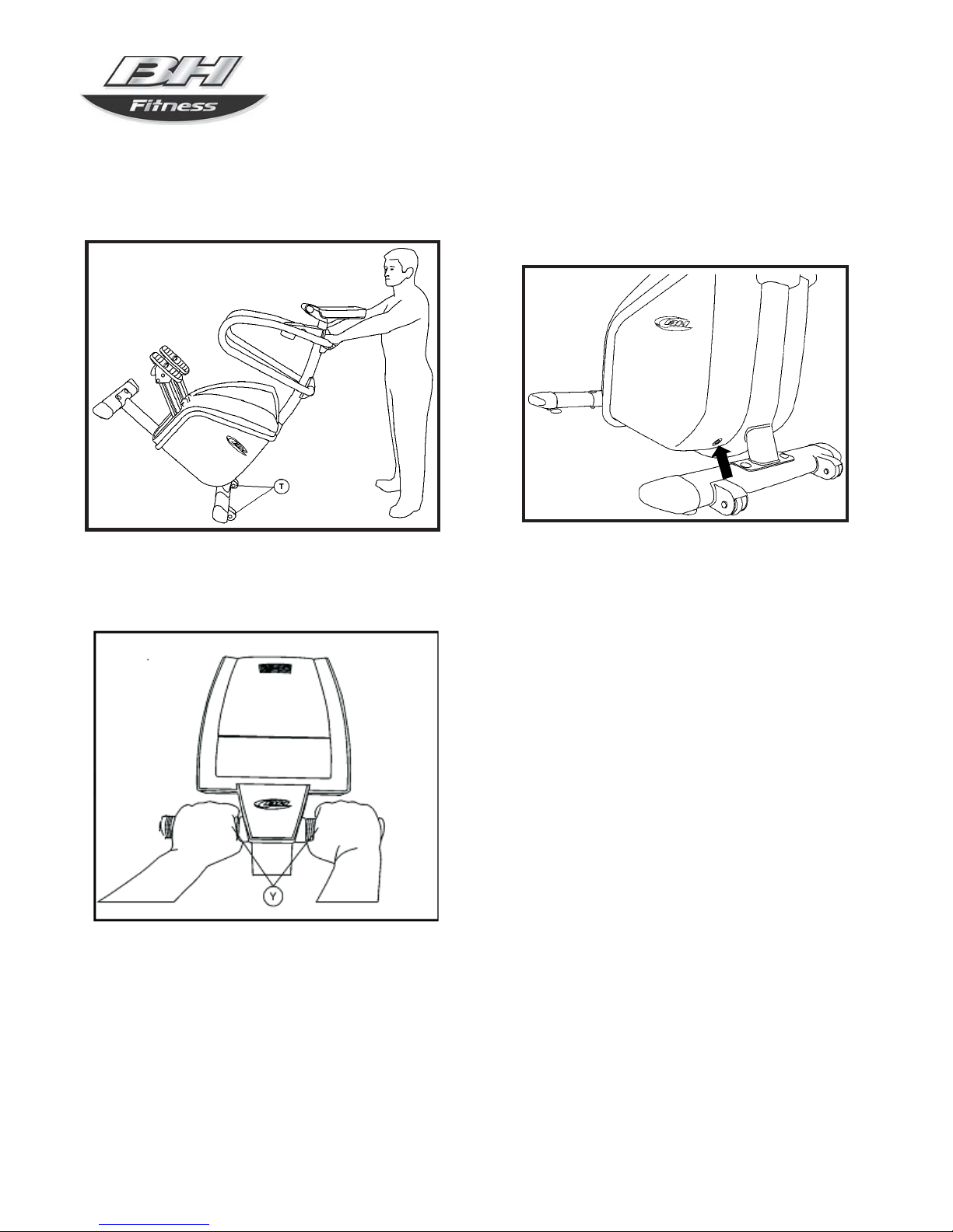
7. MOVEMENT & STORAGE
The appliance is equipped with wheels (T) making it
easier to move about. The two wheels at the front of
the appliance make it easy to store the unit away, as
shown in Fig.6.
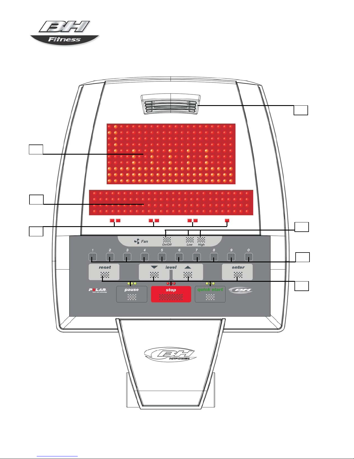
8. PULSE MEASUREMENT
Your pulse rate is measured by placing both hands
on pulse sensors (Y) located on the handlebar, see
Fig.7.
NOTE:You can also use the wirelss chest belt (not
included) to measure your heart rate. The reading
from the wireless belt pulse reading
takes precedence
over the pulse sensors (Y) located on the seat hand-
grips or handlebar.
9.BATTERY CHARGE
Before starting the battery charge, make sure that the
voltage supply is 110V-120V.
Connect the AC/DC adaptor (E) to a 110V-120V, 15
or 20 Amp dedicated outlet. Then, connect the
Adapter at the low end of the chain cover, Fig 8.