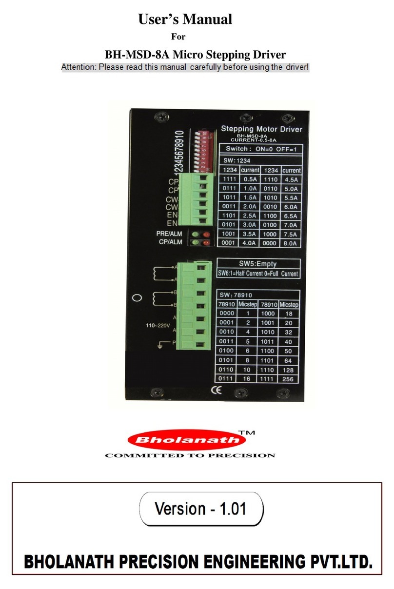
Bholanath BH-SMART-6A User manual

User’s Manual
For
BH-SMART-6A Micro Stepping Driver
NOTE:-This driver is suitable for Nema 23,24,34 and 6.5 Amp model of Nema 42 stepper
motors.

Website:-www.bholanath.in
E-mail id:-support@bholanath.in
BHOLANATH PRECISION ENGINEERING PVT. LTD.
Page |
2
Product Number Code For Micro step drive
BH SMART 6A
6 Amp
DRIVE HAVING INBUILT RPM & DIRECTION CONTROL BY
ROTARY SWITCH WITH ON/OFF SWITCH
BHOLANATH
1. D power input : 20VDC ~72VDC
2. Output current: 2A-6.5A
3. Micro stepping: 200, 400, 800, 1600,3200
4. rotect From:overheat, lock automatic half current, error connect protect
5. Dimension: 123mmx78mmx35mm
6. Weight:230g.
7. Working environment: Temperature: -15⁰C ~ +45⁰C

Website:-www.bholanath.in
E-mail id:-support@bholanath.in
BHOLANATH PRECISION ENGINEERING PVT. LTD.
Page |
3
Table o Contents
1. Introduction, Features and Applications............................................................4
Introduction...............................................................................................4
Features.................................................................................................... 4
Applications..............................................................................................4
2. Specifications................................................................................................4
Electrical Specifications..............................................................................4
Model no:-BH-SMART-6A.................................................................4
Drive prevention........................................................................................ 4
Operating Environment...............................................................................4
Elimination of Heat.................................................................................... 5
3. Pin Assignment and Description......................................................................5
Connector P1 Configurations.......................................................................5
Connector P2 Configurations.......................................................................5
External Limiting Resistance.................................................................................. 5
Rpm & Direction Control by Rotary Wheel & Switch..........................................5
Wiring Notes........................................................................................................... 6
Switch Choices....................................................................................................... 6
4. Sequence Chart Of Control Signals…………………………………………………….6
5. Calculation of pulse frequency………………………………………………………7
Frequency With Different RPM At 400 Micro Step............................................ 7
Frequency With Different RPM At 800 Micro Step............................................ 7
6. Connecting the Motor.................................................................................... 7
Connections to 4-lead Motors...................................................................... 7
Connections to 6-lead Motors...................................................................... 8
Half Coil & Full Coil Configurations ...........................................................8
Connections to 8-lead Motors...................................................................... 9
Series & Parallel Connections.....................................................................9
7. Power Supply Selection..................................................................................9
Regulated or Unregulated Power Supply....................................................... 9
Multiple Drivers........................................................................................ 9
8. Troubleshooting........................................................................................... 9
9. Dimensions................................................................................................ .11
10. FAULT OUTPUT Connection……..…………………………………………………12
11. Circuit connections Of BH SMART 6A With BH SDC-01,02...................... .12
12. Circuit connections of BH SMART 6A With Arduino & PLC..........................13
13. Frequently Asked Questions....................................................................... .15
14. Contact Us............................................................................................... .15

Website:-www.bholanath.in
E-mail id:-support@bholanath.in
BHOLANATH PRECISION ENGINEERING PVT. LTD.
Page |
4
1. Introduction, Features and Applications
Introduction
Micro stepping driver is particularly suitable for the applications desired with extremely low noise
and low temperature rise technology which significantly improve the performance of the stepper
motor that leads to low temperature rise, low vibration. With the adjustment technology (step/rev and
current) according to different motors, the driven motors automatically generate optimal parameters
for different motors, and achieve the best performance at higher speed. It is suitable for driving 2-
phase and 4-phase hybrid stepping motors.
Features
High performance, cost-effective
Suitable for 2-phase and 4-phase motors
Support PUL/DIR , CW/CCW modes and RPM control rotary wheel.
Short-voltage, over-voltage, over-current and short-circuit protection
Low temperature rise, smooth motion
Pulses Response Frequency Can Reach 200KHz
Support NPN & PNP Pulse, Direction Input.
Applications
Suitable for a wide range of stepping motors, from NEMA size 23 to 42. It can be used in various
kinds of machines, such as X-Y tables. And a variety of large-scale automation equipments and
instruments. For example: labeling machine, cutting machine, packaging machine, plotter, engraving
machine, CNC machine tools and so on. It always performs well when applied for equipment which
requires for low-vibration, low-noise, high-precision and high-velocity.
2. Specifications
Electrical Specifications
Model No:-BH-SMART-6A
Parameter Min Typical Max Unit
Input
Voltage(DC)
20
-
72
VDC
Output
current
2
-
6.5
A
DRIVE PREVENTION :-
NOTE:-Please ensure maximum voltage should not exeed 72 VD to prevent damaged to the driver.
Operating Environment
ooling Natural cooling or Forced cooling
Operating Environment Environment-Avoid dust, oil fog, corrosive gases
Temperature- -15℃
℃℃
℃-
--
-+45℃
℃℃
℃
Humidity Range:- 55RH
Storage Temperature -15℃
℃℃
℃-
--
-+45℃
℃℃
℃

Website:-www.bholanath.in
E-mail id:-support@bholanath.in
BHOLANATH PRECISION ENGINEERING PVT. LTD.
Page |
5
Elimination of Heat
Driver’s reliable working temperature should be <65
℃
℃℃
℃
, and motor working temperature
should be <80
℃
℃℃
℃
;
It is recommended to mount the driver vertically to maximize heat sink area. Use forced
cooling method to cool the system if necessary.
3. Pin Assignment and Description
The driver has two connectors namely P1 & P2, Connector P1 for control signals connection,
Connector P2 for power and motor connections. The following tables are brief descriptions of the two
connectors.
Connector P1 Configurations
Pin
Function
Details
PUL+
PULSE
SIGNAL
POSITIVE
PUL-
PULSE
SIGNAL
NEGATIVE
DIR+
DIRECTION
SIGNAL
POSITIVE
DIR-
DIRECTION
SIGNAL
NEGATIVE
ENA+
ENABLE
SIGNAL
POSITIVE
ENA-
ENABLE
SIGNAL
NEGATIVE
FAULT
+
FAULT
SIGNAL
POSITIVE
SUPPLY(EXTERNAL)
FAULT - FAULT SIGNAL STATUS OUTPUT(EMMITER FOLLOWER)
Connector P2 Configurations
Pin
Function
Details
V+
DC
POWER
SUPPLY/AC
POWER
SUPPLY
GND
GROUND
A+,A-
MOTOR
PHASE
A
B+,B- MOTOR PHASE B
EXTERNAL CURRENT LIMITING RESISTANCE: Signal current in both the“+” “-”ports,
can’t be too big and not too weak. It is necessary to connect current-limiting resistor in external, refer
to following table
RPM & DIRECTION Control by Rotary Wheel and Switch
1. Clockwise and Anticlockwise movement of Rotary wheel will give Clockwise and
Anticlockwise motion of motor.
2. To increase speed continue to rotate the wheel in same direction.
3. Once desired speed is achieved press the switch once to record the data,the motor will
stop.
4. Now you can use the switch for ON-OFF as per requirement and the saved data will
be used to rotate the motor.
5. Long press of 5 Sec or more will erase old data.
6. Repeat steps 1 to 4 for saving new data.
VOLTAGE
LIMITING
RESISTANCE(R
)
5
V
R=0
12
V
R=1K
Ω
(0.25W)
24 V R=2.2 KΩ(0.25W)

Website:-www.bholanath.in
E-mail id:-support@bholanath.in
BHOLANATH PRECISION ENGINEERING PVT. LTD.
Page |
6
Wiring Notes
To prevent noise incurred in PUL/DIR signal, pulse/direction signal wires and motor wires
should not be tied up together. It is better to separate them by at least 10 cm, otherwise the
disturbing signals generated by motor will easily disturb pulse direction signals, causing
motor position error, system instability and other failures.
If a power supply serves several drivers, separately connecting the drivers is recommended
instead of daisy-chaining.
It is prohibited to pull and plug connector P2 while the driver is powered ON, because there is
high current flowing through motor coils (even when motor is at standstill). Pulling or
plugging connector P2 with power on will cause extremely high back-EMF voltage surge,
which may damage the driver.
Switch Choice:
1.Microstepping choice:
SW 6 off on off on off
SW 7 off off on on off
SW 8 off off off off on
Micro 200 400 800 1600 3200
2.Current choice
:
::
:
SW 1 off on off on off on off on off on
SW 2 off off on on off off on on off off
SW 3 off off off off on on on on off off
SW 4 off off off off off off off off on on
Current
(A)
2 2.5 3 3.5 4 4.5 5 5.5 6 6.5
SW5:-OFF- Half Current, ON- Full Current.
Default setting is OFF i.e. Half Current. Full current to be used for increasing torque if required and for
holding torque operations. At full current motor and driver temperature will rise, kindly arrange external
cooling.
Note:-Any DIP Switch Setting other than above
Current:-The 0.5 A current will be set.
Microstep:-3200 microstep will be set.
4.Sequence Chart of Control Signals
In order to avoid some fault operations and deviations, PUL, DIR and ENA should abide by
some rules, shown as following diagram:

Website:-www.bholanath.in
E-mail id:-support@bholanath.in
BHOLANATH PRECISION ENGINEERING PVT. LTD.
Page |
7
NOTE: Enable Signal ENA+ and ENA- are to be used in case of disabling the drive when
required.This in turn will switch off the motor. Any external supply of 5 Vdc applied will disable the
Drive.
Remark:
a) t2: DIR must be ahead of PUL effective edge by 5µs to ensure correct direction;
b) t3: Pulse width not less than 1.5µs;
c) t4: Low level width not less than 1.5µs.
5.CALCULATION OF PULSE FREQUENCY:- F = (RPM MICRO STEP)/60
If Need 60 RPM at 400 Micro Step (Half Step, Default Setting)
Then Frequency = (60X400) /60
= 400Hz
TABLE :-(a)Frequency With Different RPM At 400 Micro Step
RPM 60 120 180 240 300 360 420 480 540
FREQUENCY(Hz) 400 800 1200 1600 2000 2400 2800 3200 3600
TABLE :-(b) Frequency With Different RPM At 800 Micro Step
If Need 60 RPM at 800 Micro step
Then Frequency = (60X800) /60
= 800Hz
RPM 60 120 180 240 300 360 420 480 540
FREQUENCY(Hz) 800 1600 2400 3200 4000 4800 5600 6400 7200
6. Connecting the Motor
Connections to 4-lead Motors
4 lead motors are the least flexible but easiest to wire. Speed and torque will depend on winding
inductance.

Website:-www.bholanath.in
E-mail id:-support@bholanath.in
BHOLANATH PRECISION ENGINEERING PVT. LTD.
Page |
8
Connections to 6-lead Motors
Like 8 lead stepping motors, 6 lead motors have two configurations available for high speed or high
torque operation. The higher speed configuration, or half coil, is so described because it uses one half
of the motor’s inductor windings. The higher torque configuration, or full coil, uses the full windings
of the phases.
Half Coil Configurations
As previously stated, the half coil configuration uses 50% of the motor phase windings. This gives
lower inductance, hence, lower torque output. Like the parallel connection of 8 lead motor, the torque
output will be more stable at higher speeds. This configuration is also referred to as half chopper.
6-lead motor half coil (higher speed) connections
Full Coil Configurations
Lower speeds is desired. This configuration is also referred to as full chopper. In full coil mode,
the motors should be run at only 70% of their rated current to prevent overheating.
6-lead motor full coil (higher torque) connections
NOTE:THE ABOVE CONFIGURATIONS IS FOR CONNECTING IN A BIPOLAR
MICROSTEP DRIVE AS PER APPLICATION/NON-AVAILABILITY OF A UNIPOLAR
MICROSTEP DRIVE.
Connections to 8-lead Motors
8 lead motors offer a high degree of flexibility to the system designer in that they may be connected
in series or parallel, thus satisfying a wide range of applications.
Series Connections
A series motor configuration would typically be used in applications where a higher torque at lower
speeds is required. Because this configuration has the most inductance, the performance will start to
degrade at higher speeds. In series mode, the motors should also be run at only 70% of their rated
current to prevent overheating.
8-lead motor series connections
FOR
HALF
COIL
CONNECTION
CONNECT (A+)-A om & (B+)-B om/
A
om-(A-)
&
B
om-(B-)
FOR
FULL
COIL
CONNECTION
CONNECT (A+)-(A-) & (B+)-(B-)/
LEAVE A om & B om

Website:-www.bholanath.in
E-mail id:-support@bholanath.in
BHOLANATH PRECISION ENGINEERING PVT. LTD.
Page |
9
Parallel Connections
An 8 lead motor in a parallel configuration offers a more stable, but lower torque at lower speeds. But
because of the lower inductance, there will be higher torque at higher speeds.
8-lead motor parallel connections
7. Power Supply Selection
The Microstep Driver can match Large and small size stepping motors (from Nema size 17 to Nema
size 34). To achieve good driving performances, it is important to select supply voltage and output
current properly. Supply voltage determines the high speed performance of the motor, while output
current determines the output torque of the driven motor (particularly at lower speed). Higher supply
voltage will allow higher motor speed to be achieved, at the price of more noise and heating. If the
motion speed requirement is low, it’s better to use lower supply voltage to decrease noise, heating and
improve reliability.
SMPS or Linear Power Supply
Both SMPS and Linear power supplies can be used to supply the driver. However, Linear power
supplies are preferred due to their ability to withstand current surge. If SMPS power supplies (such as
most switching supplies.) are indeed used, it is important to have large current output rating to avoid
problems like current clamp. On the other hand, if Linear supply is used, one may use a power supply
of lower current rating than that of motor (typically 50%
~
~~
~
70% of motor current). The reason is that
the driver draws current from the power supply capacitor of the Linear supply only during the ON
duration, but not during the OFF duration. Therefore, the average current withdrawn from power
supply is considerably less than motor current
Multiple Drivers
It is recommended to have multiple drivers to share one power supply to reduce cost, if the supply has
enough capacity. To avoid cross interference, DO NOT daisy-chain the power supply input pins of
the drivers. (Instead, please connect them to power supply separately).
8. Troubleshooting
a. The status on light’s indication
RUN: green, normal work light.
ERROR: red, failure light, the motor with phase short-circuit, overvoltage and undervoltage
protection.
NOTE:
TO CHECK IF DRIVE IS OK/NOT OK, CONNECT ONLY SUPPLY (AC /DC) VOLTAGE AND
GROUND TO THE MICROSTEP DRIVE AND CHECK THE LED INDICATOR IF IT SHOWS
GREEN THEN DRIVE IS OK AND IF THE LED INDICATOR SHOWS RED THEN DRIVE IS
NOT OK. THIS TEST SHOULD BE DONE WHEN THE BELOW TROUBLE SHOOTING IS
CARRIED AND MOTOR IS NOT RUNNING.

Website:-www.bholanath.in
E-mail id:-support@bholanath.in
BHOLANATH PRECISION ENGINEERING PVT. LTD.
Page | 10
2. Troubles
Problems
Possible cause
Solutions
No
power
supply
Check
the
power
supply
Motor is not
No
control
signal
Check
the
control
signal
rotating
The
driver
is
disabled
Don
’
t
connect
the
enable
signal
Supply
voltage
is
too
high
or
Check
the
supply
voltage
too
low
REDLED light
Motor
line
short-circuit
Check
motor
lines
eliminate
the
short-circuit
Motor
line
wrong
connect
Check
the
motor
wiring
Motor
or
drive
failure
Replace
the
motor
or
drive
Motor rotates in
Motor
phases
connected
in
Reverse
the
phases
line
the wrong
reverse
direction
Wrong I/p direction signal
Change
direction
setting
Motor
line
break
Change
the
phases
are
connected
Inaccurate
The
Micro
steps
set
incorrectly.
Set
the
correct
segments
The
motor
load
is
too
heavy.
Increasing
the
current
Position
Control
signal
is
interfered
Eliminate
interference
Power
supply
voltage
too
low
Increasing
the
supply
voltage
Motor Stalled
Accelerating
time
is
too
short.
Extend
the
acceleration
time
Current
setting
is
too
small
Increasing
the
current
Motor
torque
is
too
small
Replace
the
motor

Website:-www.bholanath.in
E-mail id:-support@bholanath.in
BHOLANATH PRECISION ENGINEERING PVT. LTD.
Page | 11
Problems Possible cause Solutions
Wrong
connection
for
power
Check
wiring
of
power
LED
off
turn
Low-voltages
for
power
Enlarge
voltage
of
power
Wrong
connection
of
stepper
Correct
its
wiring
Motor
doesn
’
t
run,
motor
without
holding
torque
RESET
signal
is
effective
when
offline
Make
RESET
ineffective
Motor
doesn
’
t
run,
but
Without
input
pulse
signal
Adjust
PMW
&
signal
level
maintains
holding
torque
Too
small
relative
to
current
Correct
rated
current
setting
setting
Motor
’
s
holding
torque
is
Acceleration
is
too
fast
Reduce
the
acceleration
too
small
Motor
stalls
Rule
out
mechanical
failure
Driver
does
not
match
with
Change
a
suitable
driver
The motor
9. Dimensions

Website:-www.bholanath.in
E-mail id:-support@bholanath.in
BHOLANATH PRECISION ENGINEERING PVT. LTD.
Page | 12
10.FAULT OUTPUT Connection
OR
FAULT+
FAULT-
+V
GND
FAULT
O/P
STATUS
O/P
FAULT+
FAULT-
GND
+V
FAULT
O/P
STATUS
O/P
R
R
NOTE: Maximum Current through
the Fault Switch Is 10 mAmp
Up to 12V no external resister
required
BH-SMART
BH-SMART

Website:-www.bholanath.in
E-mail id:-support@bholanath.in
BHOLANATH PRECISION ENGINEERING PVT. LTD.
Page | 13
11. Circuit connections Of BH SMART 6A With BH-SDC 01,SDC 02

Website:-www.bholanath.in
E-mail id:-support@bholanath.in
BHOLANATH PRECISION ENGINEERING PVT. LTD.
Page | 14
12. Circuit Connections Of BH SMART 6A With PLC
This is a Tentative connection Guideline for driving the Drive from Any 5V
Controller Systems.

Website:-www.bholanath.in
E-mail id:-support@bholanath.in
BHOLANATH PRECISION ENGINEERING PVT. LTD.
Page | 15
13. Frequently Asked Questions
In the event that your driver doesn’t operate properly, the first step is to identify whether the
problem is electrical or mechanical in nature. The next step is to isolate the system
component that is causing the problem. As part of this process you may have to disconnect
the individual components that make up your system and verify that they operate
independently. It is important to document each step in the troubleshooting process. You may
need this documentation to refer back to at a later date, and these details will greatly assist
our Technical Support staff in determining the problem should you need assistance.
Many of the problems that affect motion control systems can be traced to electrical noise,
controller software errors, or mistake in wiring.
The content in this manual has been carefully prepared and is believed to be accurate, but no
responsibility is assumed for inaccuracies.
We manufacture 1.8⁰ HYBRID STEPPER MOTORS of size NEMA17, NEMA23, NEMA24, and
NEMA34 in square frame and NEMA 23 in Round frame and available in our product range
are Linear Actuator Stepper Motors, Planetary Geared Stepper Motors, Stepper motors
with Brakes and Customized Stepper Motors.
BHOLANATH
STEP
SERVO
MOTOR
&
DRIVE
Table of contents
Other Bholanath Control Unit manuals
Popular Control Unit manuals by other brands

lancer
lancer 82-2684 Installation and operation manual

Woodward
Woodward MicroNet TMR 5009FT Installation and Hardware Manual
PPA
PPA POP PROG user manual
TQ
TQ TQMa 4XxL Series Preliminary user's manual
TESTO
TESTO Saveris 0573 2600 01 instruction manual
GOSUNCN
GOSUNCN GM500-U1G A Hardware development guide
Burkert
Burkert 2730 Series operating instructions
Johnson Controls
Johnson Controls Mercury 3 Series Hardware installation

ORTEC
ORTEC 426 instruction manual
BASE Electronics
BASE Electronics LV-8RCL Installation and operation manual

Sea Tel
Sea Tel DAC-2202 Installation and operation manual

ABB
ABB NPBA-01 Installation and startup guide
