3
VEGA
1.0 PREMISE
1.1 Important notices
This au oma ic dis ribu or has been designed and cons ruc ed in
full accordance wi h curren safe y regula ions and is herefore
safe for hose who follow he ordinary filling and cleaning
ins ruc ions as indica ed in his manual.
The user must not under an circumstances remove the
guards that require a tool for removal.
Some main enance opera ions ( o be done solely by specialized
echnicians and indica ed in his manual wi h a special symbol)
require ha specific safe y pro ec ions of he machine mus be
swi ched off .
In accordance wi h he curren safe y regula ions, cer ain
opera ions are he exclusive responsibili y of he ins alla ion
echnician, and he ordinary main enance echnician may have
access o specific opera ions on wi h specific au horiza ion.
The acquain ance and absolu e respec , from a echnical poin of
view, of he safe y ins ruc ions and of he danger no ices con ained
in his manual, are fundamen al for he execu ion, in condi ions
of minimum risk, for he ins alla ion, use and main enance of
his machine.
1.2 General Instru tions
Knowledge of the information and instructions contained in the
present manual is essential for a correct use of the automatic
vending machine on the part of the user .
Interventions b the user on the automatic vending machine
are allowed onl if the are of his competence and if he has
been dul trained.
The installation technician must be full acquainted with all
the mechanisms necessar for the correct operation of the
machine.
It is the bu ers responsibilit to ascertain that the users have
been trained and are informed and regulations indicated in
the technical documentation supplied.
Despite the full observance of the safet regulations b the
constructor, those who operate on the automatic dispensers
must be full aware of the potential risks involved in operations
on the machine.
This manual is an integral part of the equipment and as such
must alwa s remain inside of the same, so as to allow further
consultations on the part of the various operators, until the
dismantlement and/or scrapping of the machine.
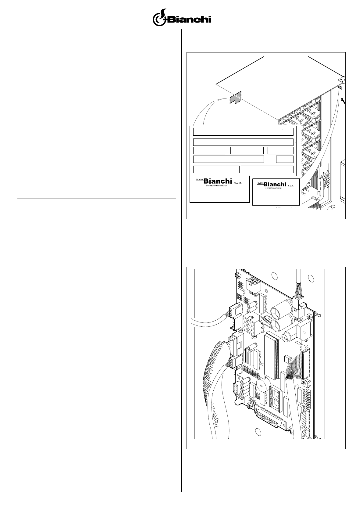
In case of loss or damage of the present manual it is possible
receive a new cop making application to the manufacturer,
with prior indication of the data registered on machines serial
number.
The functional reliabilit and optimization of machines services
are guaranteed onl if original parts are used.
Modifications to the machine not previousl agreed on with the
construction compan and undertaken b the installation
technician and/or manager, are considered to be under his
entire responsibilit .
INDEX
1.0 PREMISE
1.1 User ins ruc ions
1.2 General Ins ruc ions
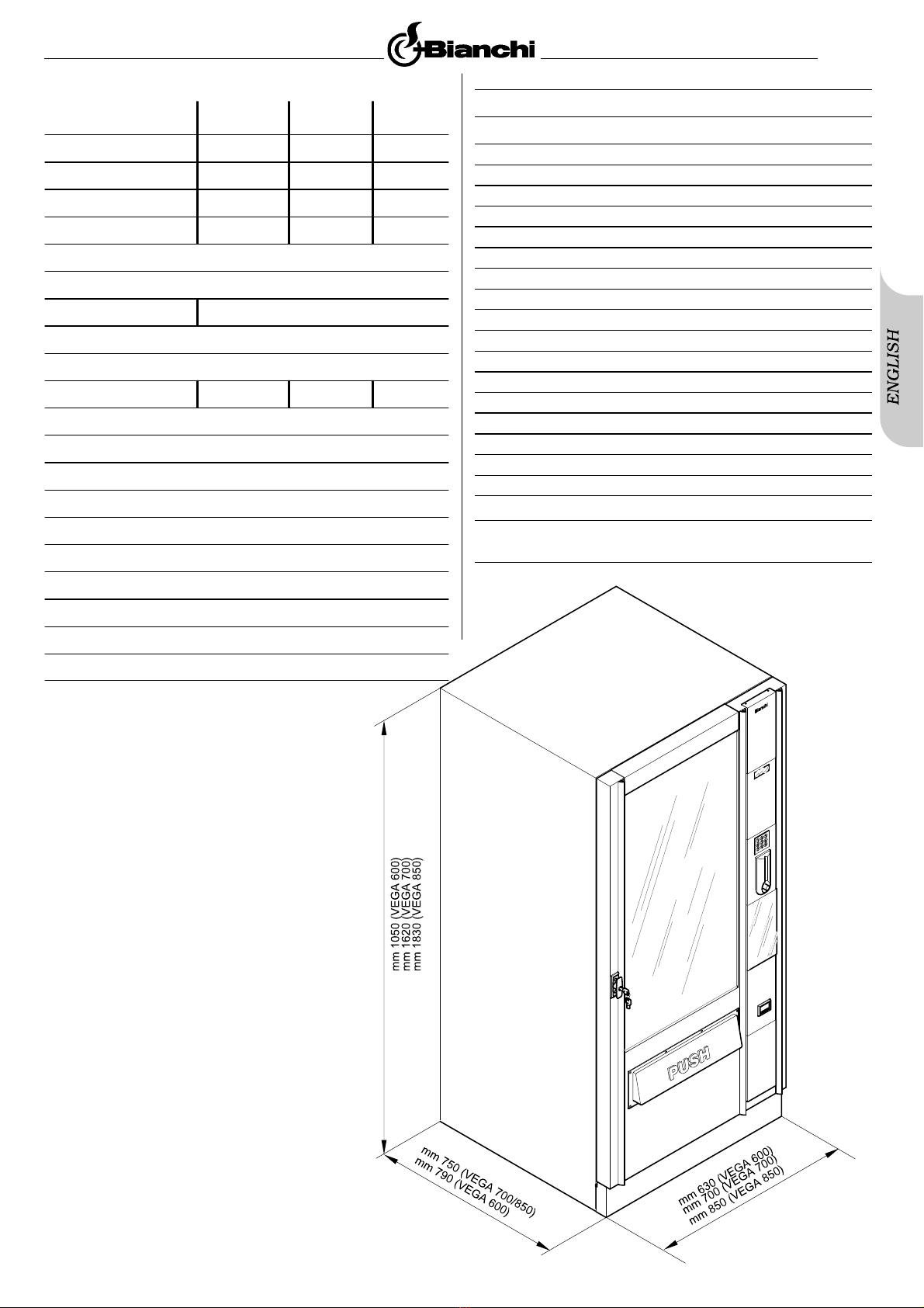
2.0 TECHNICAL CHARACTERISTICS
3.0 DESCRIPTION OF THE MACHINES TECHNICAL
CHARACTERISTICS
3.1 Descrip ion of he machine
3.2 Scheduled Use
3.3 Models
3.4 Basic ins ruc ions for he machine opera ion
4.0 TRANSPORTING THE AUTOMATIC VENDING
MACHINE
4.1 Moving and Transpor
4.2 S ocking
4.3 Packing
4.4 Recep ion
4.5 Unpacking
5.0 SAFETY RULES
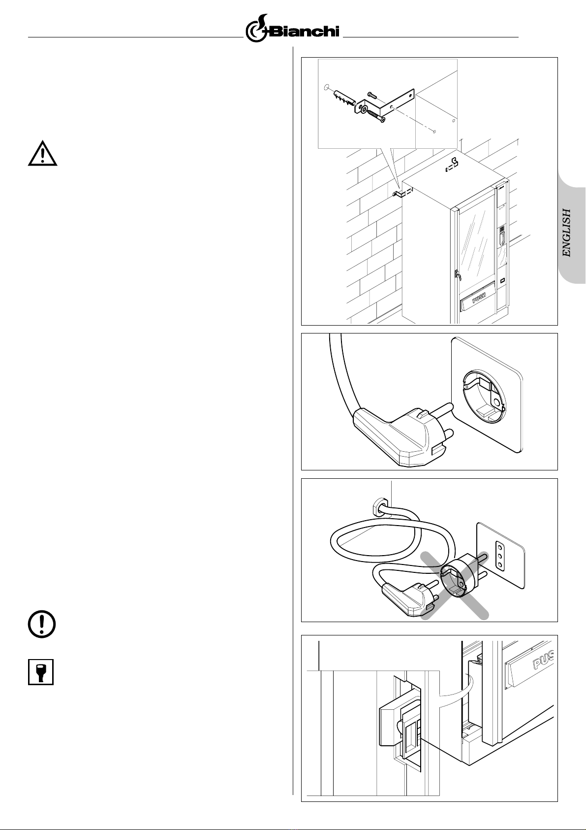
6.0 INSTALLATION
6.1 Posi ioning
6.2 Power supply connec ion
6.3 Machine s ar ing up
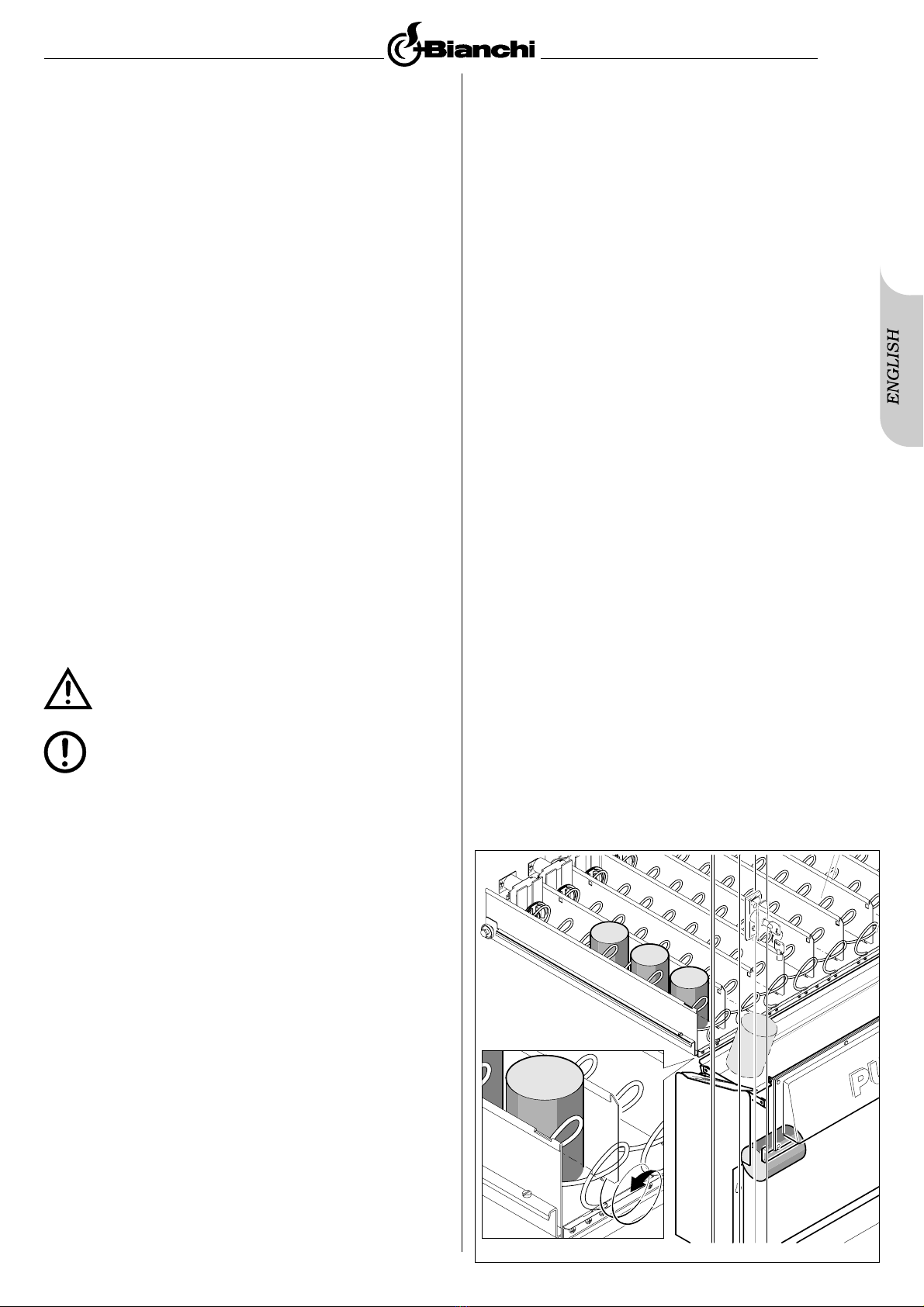
6.4 Produc loading
6.4.1 Drawer loading
6.4.2 Label applica ion
6.4.3 Pa ment s stem installation
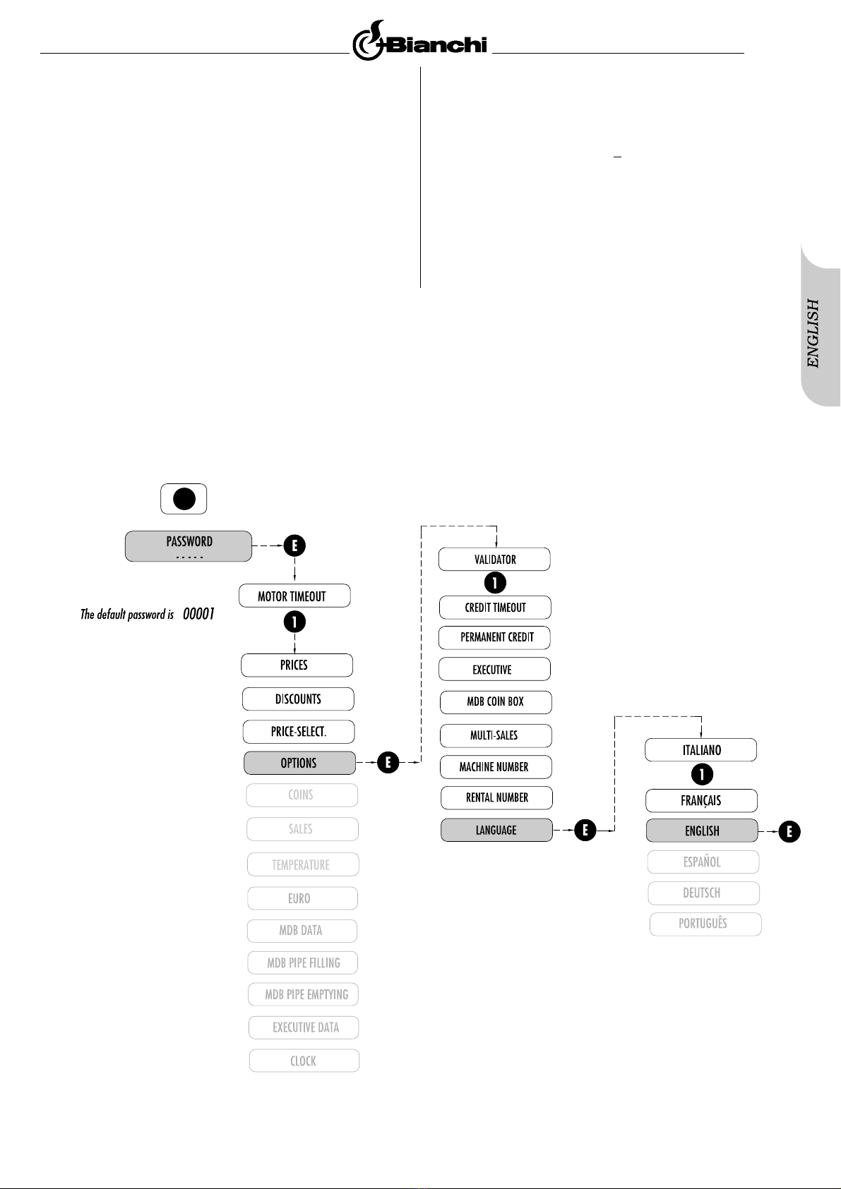
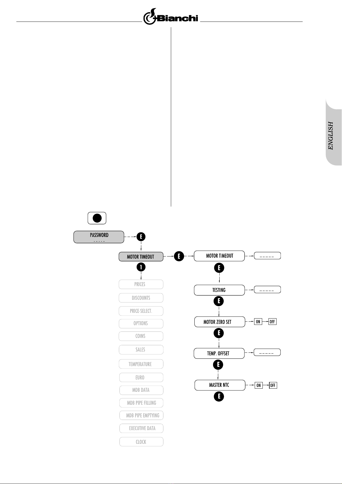
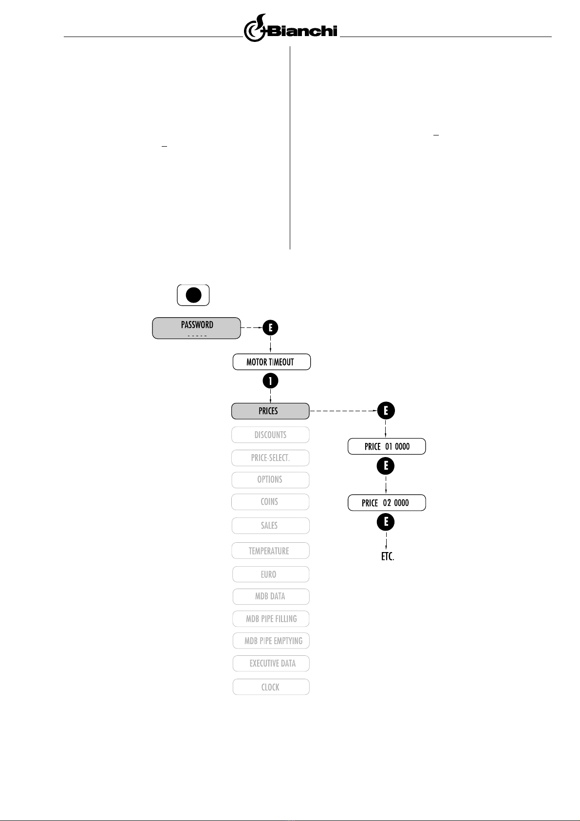
7.0 PROGRAMMING
7.1 General descrip ion and preliminary opera ions
7.2 Func ion descrip ion
8.0 SERVICE
9.0 MAINTENANCE AND INACTIVITY
9.1 Cleaning and loading
9.1.1 Procedure for distributor cleaning
9.1.2 Periodic cleaning b the maintenance
technician
9.1.3 Cleaning and maintenance
9.1.4 Product loading
9.1.6 Product storage advice
9.1.6 Ordinar and Extraordinar Maintenance
9.2 Adjus men s
9.2.1 Spirals
9.2.2 Spiral replacemen
9.2.3 Change he number of spirals per drawer
9.2.4 Change heigh be ween drawers
9.2.5 Accessories
9.3 Neon ligh replacemen
9.4 Inac ivi y
10.0 COMBINATION WITH HOT DRINK DISTRIBUTOR
10.1 Technical fea ures of LUX 700 model
(combined wi h An ares model)
10.2 Descrip ion of he machine
10.3 Connec ion for Mas er/Slave func ion
(Combined wi h An ares model)
10.4 Technical fea ures of Vega 600 model
(combined wi h Pegaso model)
10.5 Descrip ion of he machine
10.6 Connec ion for he Mas er/slave func ion
(Combined wi h Pegaso mod.)
11.0 DISMANTLEMENT
12.0 TROUBLESHOOTING GUIDE FOR THE FAILURES
OR MOST COMMON ERRORS