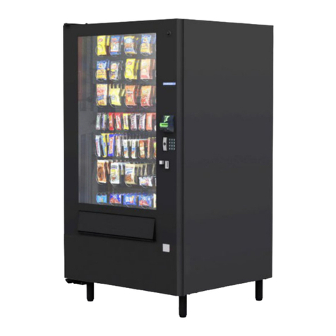
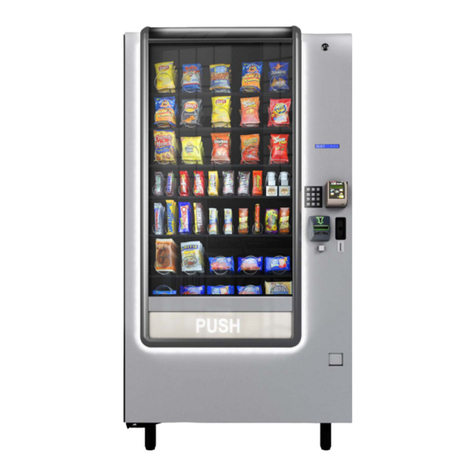
Vendors Exchange 186 User manual

1
CURVE PANEL W/ VENTURE
For Merchant Media 186/187, 471/472
INSTALLATION GUIDE
R
VE1021148 - Media Panel Installation Manual
R1.800.321.2311
8700 BROOKPARK ROAD
CLEVELAND, OHIO 44129
www.veii.com
All manuals are available at https://www.veii.com/manual

2
...............................................................................
5
STEP 1. New Controller .......................................................................
6
STEP 1. New Controller
...............................................................
6
STEP 2. Mount Door Catch and Slide Brackets
.........
7
STEP 3. Mount and Secure Door
......................................
8
STEP 4. Reassemble Door
..................................................
9
...............................................................................
9
ATTACH HARNESSE......................................................................
10
Controller Port Diagram
...........................................................
11
Venture Port Diagram
................................................................
12
INSTALLATION GUIDE
TABLE OF CONTENTS
Merchant 186/187, 471/472
Disassembly / Assembly Process for CURVE Panel w/ Venture
REMOVE DOOR
INSTALL DOOR
INSTALL DROP SENSOR
ATTACH DROP SENSOR
VE1021148 - Media Panel Installation Manual
www.veii.com
CALL US WITH QUESTIONS : 800 - 321 -2311

3
TOOLS REQUIRED
INCLUDED PARTS
6
7
8
9
10
13
12
A B C D
1
3
4
2
16
17
18
5
14 15
11
PART NUMBER
DESCRIPTION QTY
1VE7207K KEPS NUTS, ZINC, #8-32 10
2VE4684 FASTENER MOUNT CABLE
HOLDER, 3/4” 2
3VE1017112 PCB STANDOFF 4
4VE737K SCREW, 8-32 X .25 HWHTS
SLOT TC TYPE F 2
5VE4601K 6” BAR LOCK CABLE TIE 5
6VE1017104 LOCK BRACKET,
MERCHANT 2
7VE1020757 DOOR SWITCH STRIKE
PLATE MERCHANT MEDIA 1
8VE1016250 MOUNTING RAIL SPACER 4
9VE1017053 DROP SENSOR RECEIVER BD 1
10 VE1017055
DROP SENSOR TRANSMITTER
BD
1
11 VE1019478
MOUNTING ADAPTER
BRACKET
1
12 VE5801M UNIVERSAL CONTROL BD 1
13 VE1017151 MERCHANT HARNESS BD 1
14 VE7252K SCREW, 8-32 X 375 PHMS 3
15 VE1017065 RUBBER DOOR SEAL 1
16 VE4656 CABLE TIE MOUNT 3
17 VE8419 HOLD DOWN CLIP 2
18 VE6677K CABLE CLAMP 1
A5/16” SOCKET
B11/32” WRENCH
C11/32” , 1/4” NUT DRIVER
DPHILLIPS SCREW DRIVER
VE1021148 - Media Panel Installation Manual
www.veii.com

4
INCLUDED HARNESSES
1 2 34
5 6 78
910 11 12
PART NUMBER DESCRIPTION QTY
1
VE1017070 MDB HARNESS 1
2
VE6877 DROP SENSOR HARNESS 1
3
VE6822 MOTION CENSOR HARNESS 1
4
VE1017066 COIN RETURN MOTOR HARNESS 1
5
VE1017542 LED POWER HARNESS 1
6
VE1018279 DROP SENSOR HARNESS , UCB MERCHANT 1
7
VE5817 DEX HARNESS 1
8
VE1020990 DOOR SWITCH HARNESS 1
9
VE5834 DISPLAY RIBBON - HARNESS BOARD 1
10
VE1019772 VENTURE DATA HARNESS 1
11
VE1019771 VENTURE POWER HARNESS 1
12
VE1019798 SPEAKER
1
VE1021148 - Media Panel Installation Manual
www.veii.com

5
REMOVE DOOR
1.A) Unplug machine from power
outlet to prevent electrical shock.
1.D) Remove coin return motor and
bracket from OEM door and set
aside for re-use.
1.A) Locate new controller UNIVERSAL CONTROLLER (VE5801M), and
MERCHANT CONTROLLER (VE1017151) in kit and install STANDOFF
(VE1017112). Once standos are installed , remove the ends of the bottom
two standos as shown in the picture. This will decrease the pressure on
the board as harnesses are installed.
1.B) Mark the tray connectors or wires
going to the controller in such a way
to identify them for re-assembly with
the new controller. Tray 1 connector
is located at the top.
1.E) Remove fasteners that hold the
slides to the door, then remove door.
Do not remove the OEM slides from
the cabinet. They will be used to
mount the new door.
1.B) Mount new controller in cabinet,
then secure with the OEM screws you
removed earlier.
1.C) Unplug all harnesses from the
controller.
1.F) Remove OEM controller from
cabinet and retain all screws and
standos.
ATTACH HARNESSES INSTALL DROP SENSOR REMOVE DOORINSTALL DOOR
STEP 1. New Controller
INSTALL NEW DOOR
REMOVE DOOR
WARNING
To prevent personal injury and equipment damage, turn machine o and disconnect electrical cord from the wall
outlet before installing door. Failure to do so could result in electrical shock.
!
!
VE1021148 - Media Panel Installation Manual
www.veii.com
TRAY1TRAY1

6
1.D) Attach cabinet harnesses to
controller.
1.C) Attach the Merchant harness
board (VE1017151) to the UCB as
shown.
STEP 2. Mount Door Catch and Slide Brackets
REMOVE DOOR INSTALL DROP SENSOR ATTACH HARNESSES
INSTALL NEW DOOR
2.B) Depending on the machine,
the door may need MOUNTING
SPACER or ”SHIMS” (VE1016250)
to help align the door side-to-side.
Adjust. Four shims are provided if
necessary.
2.C) Install MOUNTING PLATE
(VE1019478) to lower left rail using
three (
VE7207K
) nuts. Ensure slots
face up.
2. A ) Check the LOCK BRACKET
(VE1017104) already secured to the
cabinet against the one included in
the kit. If the width on the new one
is equal to or smaller than the old
one, no need to replace. If not the
case, replace with the included wider
LOCK BRACKET (VE1017104).
1.E) NOTE: The 24VAC is installed
dierently than OEM, and it has no
directional key.
2.F) Install nuts loosely onto lower slide
studs.
2.E) Pull out upper slide and mount to
door. Install nuts loosely.
2.D) Hold door in vertical position
and stand up to hold the door
near the top.
INSTALL DOOR
VE1021148 - Media Panel Installation Manual
www.veii.com
HARNESS BOARD
UCB
SLOTS MUST
POINT UP

7
ATTACH HARNESSES INSTALL DROP SENSOR INSTALL DOOR REMOVE DOOR
INSTALL NEW DOOR
3.A) Empty included box of kit
contents and place on its side
between the door and cabinet,
near the upper slide. Tighten all
nuts on upper slide.
3.C) Close door slowly. Adjust door
position on slides so that the door is
parallel with the cabinet. Verify that
the shim placement allows for the
correct side-to-side alignment.
3.B) Close the door evenly against the
box between the door and cabinet
as shown. Tighten the middle nut
on right slide only.
3.D) Tighten all fasteners. 3.F) Install RUBBER DOOR SEAL
(VE1017065) on left side edge of
door as shown. Ensure it is pushed on
firmly and completely.
STEP 3. Mount and Secure Door
3.E) Install DOOR SWITCH (VE159A)
and DOOR STRIKE PLATE
(VE1020757) if not present. Adjust
door switch
2.G) Pull out the lower left rail with the mounting plate installed. Using three
8-32 X 375 PHMS screws (VE7227) secure the door to the mounting plate
as shown.
2.H) Pull out lower right slide and
mount door onto studs with nuts
(VE7207K).
VE1021148 - Media Panel Installation Manual
www.veii.com
SLOTS MUST
POINT UP

8
4.A) Close door and ensure the
t-handle operates smoothly, it
should engage the door catches
easily and without excessive
force. Adjust door catches in
cabinet, if necessary.
4.B) Secure the Coin return motor and mount to the coin mech mounting
bracket.
STEP 4. Reassemble Door
REMOVE DOOR INSTALL DOOR INSTALL DROP SENSOR ATTACH HARNESSES
INSTALL NEW DOOR
INSTALL DROP SENSOR
1.A) Remove screws from OEM drop
sensor boards and remove covers.
Retain screws and covers for use
with new sensors.
Unplug OEM drop sensor boards,
and dispose of the boards and
harnessing.
1.B) Mount new DROP SENSOR
RECEIVER BOARD (VE1017053)
on payment side and DROP
SENSOR TRANSMITTER BOARD
(VE1015055) to left side bucket
using the retained screws and
covers.
1.C) Attach DROP SENSOR HARNESS
(VE6877) that runs between the
drop sensor boards.
1.D) Attach DROP SENSOR HARNESS
FOR UCB (VE1018279) and route
behind slide and then to UCB as
shown.
PAYMENT SIDE
LEFT SIDE
VE1021148 - Media Panel Installation Manual
www.veii.com

9
ATTACH HARNESSES
1.B) Connect DISPLAY RIBBON
HARNESS (VE5834) to controller.
1.E) Connect UCB MOTION SENSOR
HARNESS (VE1017101) to motion
sensor board. Route along side
channel as shown and connect to
Venture Board.
1.C) Connect DOOR SWITCH HARNESS
(
VE1019798)
to door switch and
UCB.
1.F) Connect MDB HARNESS
(VE1017070) to controller and route
to door payment systems.
1.A) Connect LED POWER HARNESS
(VE1017542) to controller and
route downward behind slide to
connect to OEM harness.
1.D) Connect COIN RETURN MOTOR
HARNESS (VE1017066) between
motor and controller.
1.G) Connect DEX HARNESS
(VE5817) to controller and route
to accessible location, or to
payment systems.
ATTACH HARNESSES INSTALL DROP SENSOR INSTALL DOOR REMOVE DOOR
1.H) Connect VENTURE POWER HARNESS (
VE1019772)
to Venture board and
UCB.
CAUTION
!
Inspect all electrical connections, making sure they are properly attached to their specified connection points
before powering up machine.
Board must
point up
VE1021148 - Media Panel Installation Manual
www.veii.com
STEP 1. Attach Harnessing

10
2.B) Wrap the loose end of the ground
wire around the preexisting bundle.
Feel free to use cable ties if
Preferred.
2.C) Place the open end of the ground
wire over the stud indicated above.
Using a nut secure the ground wire
in place.
2.A) Using a screw , secure one end
of the ground wire to the cabinet.
Position the screw towards the
back end of the cabinet boss.
Ensure the screw does not
protrude out of the cabinet.
REMOVE DOOR INSTALL DOOR INSTALL DROP SENSOR ATTACH HARNESSES
ATTACH HARNESSES
1.I) Connect VENTURE DATA HARNESS (
VE1019771)
to venture board and UCB.
1.K)
Connect P-CLAMP (VE4684) to door slide. Route harnessing as shown and secure with cable ties in locations specified
in the following pictures.
1.J) Secure loose wires with CABLE TIES
(VE4601K).
*Proceed to the next two pages for UCB & Venture Harnessing Diagrams*
VE1021148 - Media Panel Installation Manual
www.veii.com
Ground Wire
STEP 2. Attach Ground Wire

11
TRAY 2
MDB
VENTURE DATA
POWER FOR
VENTURE DISPLAY
DOOR SWITCH
ESCROW MOTOR
TRAY 3
TRAY 1
TRAY 5
TRAY 6
TRAY 4
TRAY 7
DISPLAY
DROP SENSOR
24VAC
LED CONTROL
HEATER/LED*
ONLY IF USING OEM
LEDS
COMP/EVAP
24VDC
NO CONNECTION
TEMP EVAP TEMP CONDENSER TEMP CABINET
ONLY USED
FOR CHILLED
MACHINE
CONTROLLER PORT DIAGRAM
PUSH BUTTON
DEX
VE1021148 - Media Panel Installation Manual
www.veii.com

12
USB 1 USB 2
POWER
MOTION
SENSOR
SPEAKER
DATA
VENTURE PORT DIAGRAM
SCAN THE QR CODE BELOW FOR UCB PROGRAMMING GUIDES
VE1021148 - Media Panel Installation Manual
www.veii.com

VENDORS EXCHANGE WARRANTY INFORMATION
Limited Warranty and Disclaimer. VE warrants that the Products, including without limitation, their component Part(s), sold will be of the
kind and quality described herein and will be free of defects in workmanship or material. This Warranty shall extend for the Warranty Period
set forth below following the date of delivery of such Products to Buyer. VE MAKES NO WARRANTY, EXPRESS, IMPLIED (INCLUDING BUT
NOT LIMITED TO WARRANTIES OF MERCHANTABILITY AND FITNESS FOR INTENDED PURPOSES), OR STATUTORY, OTHER THAN THE
FOREGOING EXPRESS WARRANTY.
PRODUCT WARRANTY PERIOD
A. REPLACEMENT PARTS
New Replacement Parts 90 DAYS
UCB™ Kits 1 YEAR
Rowe Bill Changer Kits 1 YEAR
CleanLife® LED Bulbs MANUFACTURER
New MEI/CPI Mechs and Validators 2 YEARS
Reconditioned Mechs and Validators 6 MONTHS
Reconditioned Control Boards 6 MONTHS
B. REPAIR SERVICES
Standard Warranty 1 YEAR
Flat Rate Repairs 1 YEAR
C. EQUIPMENT
REVISION™ Door 1 YEAR
CURVE™ Door 1 YEAR
Café CURVE™ Door 1 YEAR
CURVE PANEL™ Door 1 YEAR
VE Kiosk™ 1 YEAR
A-1 Remanufactured Machine 90 DAYS
Clean, Checked and Working Machine 30 DAYS
As-Is Machine NO WARRANTY
New MFG WARRANTY
a.) Failure of the Buyer to submit any claim hereunder within ten (10) days following expiration of the Warranty Period applicable to such
Products shall be an admission by the Buyer and conclusive proof that such articles are in every respect as warranted and shall release VE
from any and all claims for damage of loss sustained by the Buyer. In the event the Buyer timely submits a claim for breach of WARRANTY,
the parties agree that, at VE’s option, the Buyer’s sole and exclusive remedies shall be the repair or replacement of the defective Products
or Part(s) or a refund of the price of the defective Products or Part(s).
b.) The Buyer acknowledges that it alone has determined that the Products purchased hereunder shall suitably meet the requirements of its
intended function. It is expressly understood that any technical advice or recommended operating practices furnished by VE with respect to
the use of the Products is given without charge, and VE assumes no obligation or liability for the advice or recommended operating practices
given, or results obtained, all such advice or recommended operating practices being given and accepted at the Buyer’s risk.
c.) This Warranty does not apply to (i) electrical components, wiring, circuits and/or mechanical parts or assemblies damaged as a result
of operating the Products at other than 115 volts, 60 Hertz current, (ii) Products damaged due to vandalism, fire, flood or other casualty,
(iii) Products not maintained in accordance with the manufacturer’s or VE’s recommendations, and/or (iv) Products not serviced by VE
authorized service personnel or which contain replacement parts not furnished by VE or its authorized service personnel.
For additional information please review the Terms and Conditions of Sale.
13
VE1021148 - Media Panel Installation Manual
www.veii.com
This manual suits for next models
3
Table of contents
Other Vendors Exchange Vending Machine manuals
Popular Vending Machine manuals by other brands
Sielaff
Sielaff SU 1500 EC02 Series Original operating instructions

Elektral
Elektral TRU-VEND Maxi-Buffet Instructions for use & maintenance manual

Westomatic
Westomatic EVOLVE Installing

WAYFARER
WAYFARER TGX150 Service manual

Royal Vendors
Royal Vendors RVV 700 Operation and service manual

GPL
GPL 6500 Set-Up / Programming / Parts Guide

Royal Vendors
Royal Vendors TDV Helpful hints

American Games
American Games MAXIM 4200 Operator's manual

DONG GU ELECTRONICS
DONG GU ELECTRONICS DG-108F3M manual

Lektro-Vend
Lektro-Vend VS-99-D Service manual

Westomatic
Westomatic H2O Installation & maintenance guide

Cafection
Cafection EMBLEM Service & installation manual