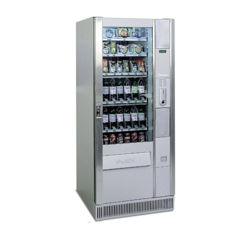
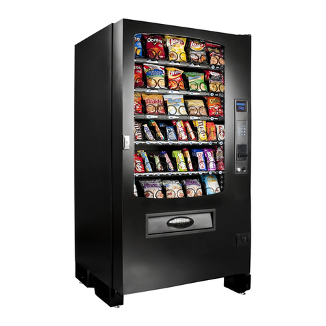
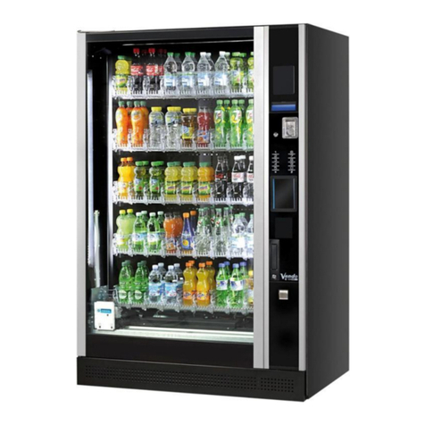
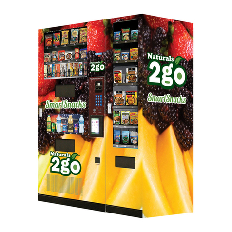
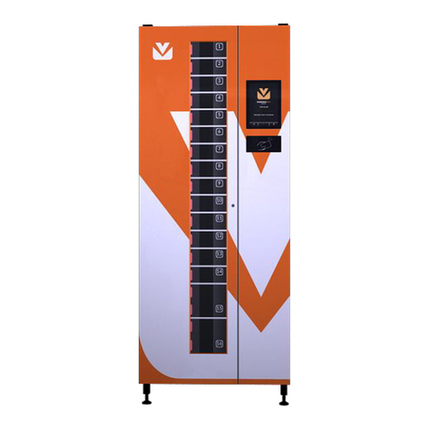
Bianchi Vista L User manual

CERT. N° 9191 BNVN
UNI EN ISO 14001:2004
CERT. N° 9105 BNVD
UNI EN ISO 9001:2008
MANUALE USO E MANUTENZIONE
Istruzioni Originali
USE AND MAINTENANCE MANUAL
Translations of the Original Instructions
MANUAL DE INSTALACION Y MANTENIMENTO
Traducciones de las instrucciones originales
MANUEL D’EMPLOI ET ENTRETIEN
Traductions des instructions originales
HANDBUCH FÜR GEBRAUCH UND WARTUNG
Übersetzung der originalen Anweisungen
MANUAL DE USO E MANUTENÇÃO
Traduções das Instruções originais
MODEL / DESIGNATION: CS/1423H3S
CS/2423H3S
www.vendival.com
Tel. 902 07 07 59 Whastapp 615 35 50 96

For further information, please log on to Bianchi Vending Group’s new portal
http://webshop.bianchivending.com, which can be accessed via a USERNAME and
PASSWORD that can be obtained directly from Bianchi Vending at info@bianchivending.com
only if you possess a customer code.
The FIRST INSTALLATION and SPARE PARTS UNDER WARRANTY forms can be down-
loaded from https://www.bianchivending.com - Quick links – Warranty.
Pour tout renseignement complémentaire, téléchargez les informations sur le nouveau
portail Bianchi Vending Group à l’adresse http://webshop.bianchivending.com.
Pour y accéder, vous avez cependant besoin d’avoir un IDENTIFIANT et un MOT DE
PASSE, que vous devez demander directement à Bianchi Vending à l’adresse de courrier
électronique info@bianchivending.com uniquement si vous possédez un code client.
Vous pouvez télécharger les formulaires de PREMIÈRE INSTALLATION et de PIÈCES
DÉTACHÉES SOUS GARANTIE sur le site institutionnel:
https://www.bianchi vending.com à la rubrique « Liens rapides - Garantie ».
Nähere Informationen können vom neuen Portal von Bianchi Vending Group unter der
Aderesse http://webshop.bianchivending.com heruntergeladen werden. Für den
Zugriff muss der Benutzer in Besitz einer USERNAME und eines PASSWORTS sein,
der Eingabe einer eigenen Kundennummer eingeholt werden können.
Die Formulare der ERSTEN INSTALLATION und ERSATZTEILE IN GARANTIE kön-
nen dagegen auf der institutionellen Webseite https://www.bianchivending.com
unter “Quick links – Garanzia” heruntergeladen werden.
Maiores informações podem ser baixadas do novo portal da Bianchi Vending Group no
endereço: http://webshop.bianchivending.com. Porém, para acessar ao mesmo é
necessário possuir um USERNAME e SENHA que podem ser solicitados diretamente
um código cliente.
Por outro lado, os módulos de PRIMEIRA INSTALAÇÃO ePEÇAS DE REPOSIÇÃO
EM GARANTIA podem ser baixados do site institucional:
https://www.bianchivending.com no ponto “Quick links – Garantia”.
ENGLISH
ESPAÑOL
FRANÇAIS
DEUTSCH
PORTUGUÊS
Otras informaciones se pueden descargar en el nuevo portal de Bianchi Vending Group en la di-
rección http://webshop.bianchivending.com . Para acceder es necesario poseer un NOMBRE
DE USUARIO yuna CONTRASEÑA que pueden pedirse directamente a Bianchi Vending en la
Los módulos de PRIMERA INSTALACIÓN yREPUESTOS EN GARANTÍA se pueden descargar
desde la web institucional: https://www.bianchivending.com con la opción “Quick links –
Garantía”.
Maggiori informazioni si possono scaricare dal nuovo portale di Bianchi Vending Group all’indirizzo:
http://webshop.bianchivending.com . Per accedervi è però necessario essere in possesso di
USERNAME e PASSWORD che possono essere richiesti direttamente a Bianchi Vending all’indi-
I moduli di PRIMA INSTALLAZIONE e RICAMBI IN GARANZIA possono essere invece scaricati
dal sito istituzionale: https://www.bianchivending.com sotto la voce “Quick links – Garanzia”.
www.vendival.com
Tel. 902 07 07 59 Whastapp 615 35 50 96

3
ITALIANO
DICHIARAZIONE DI CONFORMITA’
La BIANCHI VENDING GROUP S.p.A.
Corso Africa, 9 - 24040 Zingonia di VERDELLINO (BG) Italia
Dichiara sotto la propria responsabilità che le famiglie di prodotto:
Distributori automatici di bevande calde e fredde
Distributori automatici a spirali per prodotti freddi
Macchine per caffè ad uso professionale
Marca: BIANCHI VENDING
Fabbricante: BIANCHI VENDING GROUP S.p.A.
Anno di costruzione: 2014
Sono conformi alla Direttiva: RoHS 2
RoHS 2 - Direttiva 2011/65/UE del Parlamento Europeo e del Consiglio del 8 giugno 2011, sulla restrizione dell’uso di determinate sostanze pericolose
nelle apparecchiature elettriche ed elettroniche (AEE).
Si dichiara inoltre che, dal 3 gennaio 2013, qualsiasi prodotto BIANCHI VENDING GROUP S.p.A. immesso nello Spazio Economico Europeo
(UE+Liechteinstein + Islanda + Norvegia) è conforme alla Direttiva RoHS 2, quindi non contiene sostanze con concentrazioni superiori ai limiti sotto
elencati (*):
•Piombo [Pb] 0,1%
•Mercurio [Hg] 0,1%
•Cadmio [Cd] 0,01%
•Cromo esavalente [Cr(VI)] 0,1%
•Bifenili polibromurati [PBB] 0,1%
•Eteri di difenile polibromurato [PBDE] 0,1%
(*) Allegato II - Sostanze con restrizione di cui all’Articolo 4(1) e valori di concentrazione massima tollerata, in peso, di materiali omogenei.
Zingonia di Verdellino (BG), GENNAIO 2014
DICHIARAZIONE DI CONFORMITA’
La BIANCHI VENDING GROUP S.p.A.
Corso Africa, 9 - 24040 Zingonia di VERDELLINO (BG) Italia
Dichiara sotto la propria responsabilità che la famiglia dei distributori automatici:
Marca: BIANCHI VENDING
Fabbricante: BIANCHI VENDING GROUP S.p.A.
Tipo/Modello: CS Des.: 1423H3S; 2423H3S
Nome commerciale: VISTA L/M slave
Distributore automatico a spirali per prodotti freddi
FASCICOLO TECNICO custodito presso Ufcio Tecnico BVG Sede. - Anno di costruzione: 2014 -
E’ conforme ai Requisiti Essenziali delle Direttive:
1) Bassa Tensione 2006/95/CE (Concernente il ravvicinamento delle legislazioni degli Stati membri relative al materiale elettrico destinato ad essere
adoperato entro taluni limiti di tensione) -BT-
2) Direttiva macchine 2006/42/CE e successive modiche e integrazioni, recepita in Italia dal D.Lgs. 17/2010 -DM-.
(Requisiti essenziali di sicurezza e di tutela della salute relativi alla progettazione e alla costruzione delle macchine).
3) Compatibilità Elettromagnetica 2004/108/CE (Concernente il ravvicinamento delle legislazioni degli Stati membri relative alla compatibilità
elettromagnetica) -EMC-
4) REG. (CE) 1935/2004 riguardante i materiali e gli oggetti destinati a venire a contatto con i prodotti alimentari.
REG. (CE) 1895/2005 relativo alla restrizione dell’uso di alcuni derivati epossidici in materiali e oggetti destinati a entrare in contatto con prodotti alimentari.
DIR. 2002/72 CE relativa ai materiali e agli oggetti di materia plastica destinati a venire a contatto con i prodotti alimentari.
Le prove / veriche sono state eseguite in accordo alle vigenti Norme Armonizzate / Europee:
1) SICUREZZA (Bassa Tensione – Direttiva Macchine):
EN 60335-1:2002 +A1:2004 +A11:2004 +A2:2006 +A12:2006 +A13:2008 +A14:2010 +A15:2011
(Sicurezza degli apparecchi elettrici d’uso domestico e similare - Norma generale).
EN 60335-2-75:2004+ A1:2005 +A11:2006 + A2:2008 +A12:2010 (Norme particolari per distributori commerciali e apparecchi automatici per la vendita).
EN 60335-2-24:2010 (Norme particolari per apparecchi di refrigerazione, apparecchi per gelati e produttori di ghiaccio).
EN ISO 11201:2010 +EN ISO 3744:2009 (Misurazione del rumore acustico). Livello Pressione Sonora : LpA < 70 dB(A).
2) COMPATIBILITA’ ELETTROMAGNETICA (EMC):
EN 55014-1:2006 +A1:2009 (Limiti e metodi di misura delle caratteristiche di radiodisturbo degli apparecchi elettrodomestici, e similari a motore o termici,
degli utensili e degli apparecchi elettrici similari).
EN 55014-2:1997 +A1:2001 +A2:2008 (Requisiti di immunità per apparecchi elettrodomestici, utensili e degli apparecchi elettrici similari).
EN 61000-3-2: 2006 +A1:2009 +A2:2009 (Limiti per le emissioni di corrente armonica).
EN 61000-3-3:2008 (Limitazione delle uttuazioni di tensione e dei icker in sistemi di alimentazione in bassa tensione per apparecchiature con corrente nominale ≤ 16 A)
EN 62233:2008 (Metodi di misurazione dei campi elettromagnetici di elettrodomestici e apparecchi simili per quanto riguarda l’esposizione umana).
Inoltre, dichiara che i distributori in calce, se utilizzati secondo le procedure descritte nei manuali d’uso e manutenzione, sono conformi ai requisiti generali
e specici richiesti dal Regolamento (CE) Nr. 852/2004 Allegato 2, Capitolo III, paragra 1 e 2g.
Zingonia di Verdellino (BG), GENNAIO 2014
INFORMAZIONE AGLI UTENTI
Ai sensi del Decreto Legislativo 25 settembre 2007, n. 185 e dell’ art. 13 del Decreto Legislativo 25 luglio 2005, n. 151” Attuazione delle Direttive 2002/95/
CE, 2002/96/CE e 2003/108/CE, relative alla riduzione dell’uso di sostanze pericolose nelle apparecchiature elettriche ed elettroniche, nonché allo smal-
timento dei riuti”.
Il simbolo del cassonetto barrato riportato sull’apparecchiatura indica che il prodotto alla ne della propria vita utile deve essere raccolto separa-
tamente dagli altri riuti.
L’utente dovrà, pertanto, conferire l’apparecchiatura giunta a ne vita, agli idonei centri di raccolta differenziata dei riuti elettronici ed elettrotecnici,
oppure riconsegnarla al rivenditore al momento dell’acquisto di una nuova apparecchiatura di tipo equivalente. L’adeguata raccolta differenziata per l’avvio
successivo dell’apparecchiatura dimessa al riciclaggio, al trattamento e allo smaltimento ambientalmente compatibile, contribuisce ad evitare possibili
effetti negativi sull’ambiente e sulla salute e favorisce il riciclo dei materiali di cui è composta l’apparecchiatura. Lo smaltimento abusivo del prodotto
da parte dell’utente, comporta l’applicazione delle sanzioni amministrative di cui al D.Lgs. n. 22/1997 (articolo 50 e seguenti del D.Lgs. n. 22/1997).
Amministratore Delegato
Luca Parolari
Amministratore Delegato
Luca Parolari
www.vendival.com
Tel. 902 07 07 59 Whastapp 615 35 50 96

4
ITALIANO
PE
SIMBOLOGIA DI SICUREZZA
PITTOGRAMMI
ATTENZIONE: Importanti indica-
zioni per la sicurezza!
LEGGERE attentamente il manua-
le di istruzioni prima della messa
in servizio
AVVERTENZE IMPORTANTI
MANUTENTORE
TECNICO INSTALLATORE
INDICE CAPITOLI
PREMESSA
1.0 CARATTERISTICHE TECNICHE
2.0 DESCRIZIONE DEL FUNZIONAMENTO
3.0 MOVIMENTAZIONE DEL DISTRIBUTORE AUTOMATICO
4.0 INSTALLAZIONE
5.0 ISTRUZIONI SOFTWARE
6.0 MANUTENZIONE E INATTIVITÀ
7.0 SMANTELLAMENTO
PRIMADI UTILIZZARE LAMACCHINA, LEGGEREATTENTAMENTE QUESTO MANUALE PER UN IMPIEGO CORRETTO IN CONFORMITA’AI REQUISITI ESSENZIALI DI SICUREZZA.
Per ogni intervento di manuten-
togliere l’alimentazione
elettrica
ATTENZIONE: -
sione
PREMESSA
I - Avvertenze per l’operatore
Questo distributore automatico è stato progettato e costruito nel pieno ri-
spetto delle normative vigenti concernenti la sicurezza e risulta essere sicuro
per le persone che seguano le istruzioni di caricamento e pulizia ordinaria
riportate in questo manuale.
-
Alcune operazioni di manutenzione (da effettuarsi ad opera solamente di
tecnici specializzati ed indicate in questo manuale da un pittogramma appo-
sito) richiedono un deliberato aggiramento di alcune protezioni di sicurezza
del distributore.
Nel rispetto delle normative di sicurezza, alcune operazioni sono di esclu-
siva competenza del tecnico installatore e solo su specica autorizzazione
anche l’operatore addetto alla manutenzione ordinaria può avere accesso
ad operazioni speciche.
La conoscenza ed il rispetto assoluto, dal punto di vista tecnico delle av-
vertenze di sicurezza e degli avvisi di pericolo contenuti in questo manuale,
costituiscono il presupposto per l’esecuzione, in condizione di minimo rischio,
dell’installazione, la messa in esercizio, la conduzione e la manutenzione
della macchina.
II - Avvertenze generali
-
La conoscenza delle informazioni e delle prescrizioni contenute nel presente
manuale è essenziale per un corretto uso del distributore automatico, da
parte dell’utente.
Il tecnico installatore deve essere precedentemente addestrato ed istruito
sugli interventi da eseguire sul distributore automatico e limitarli a quanto
di sua competenza.
Il tecnico installatore deve essere a conoscenza dei meccanismi di funziona-
mento del distributore automatico.
– E
-
-
-
-
-
-
-
Bianchi Vending Group S.p.A.
Bianchi Vending Group S.p.A.,
Gli eventuali problemi tecnici che si possono vericare sono facilmente risol-
vibili consultando il presente manuale; per ulteriori informazioni, contattare
il concessionario presso il quale il distributore automatico è stato acquistato,
oppure contattare il Servizio Tecnico ai seguenti numeri:
ATTENZIONE!
Indicazione di messa a terra
CHIAVI A TUBO
n° 5,5 - n° 7 - n° 8 - n° 10 - n° 20 - n° 22
CHIAVI FISSE (a forchetta)
n° 7 - n° 8 - n° 10 - n° 12 - n° 14
e del
CACCIAVITI
Taglio piccolo
Taglio medio
Taglio grande
Croce normale
Croce piccolo
Croce medio
Croce grande
In Teon a taglio piccolo per tarare Trimmer
N° 1 Chiave
CHIAVE CRICK n° 14
TESTER
FORBICI ELETTRICISTA
KIT DI PROGRAMMAZIONE
Utensili necessari per poter fare interventi nel distributore automatico.
Non toccare con le mani
www.vendival.com
Tel. 902 07 07 59 Whastapp 615 35 50 96

5
ITALIANO
Il manuale è redatto per il modello più completo: è possibile, quindi,
trovare descrizioni o spiegazioni non attinenti alla propria macchina.
III - Norme per la sicurezza
-
– Le operazioni di installazione e manutenzione, devono essere eseguite
esclusivamente da personale tecnico qualicato.
– L’utente non deve in alcun modo poter accedere a quelle parti del distri-
butore automatico le cui protezioni sono bloccate da mezzi che richiedano
un utensile per essere liberati.
– La conoscenza ed il rispetto assoluto, delle avvertenze di sicurezza e degli
avvisi di pericolo contenuti in questo manuale, costituiscono il presupposto
per l’esecuzione, in condizione di minimo rischio, dell’installazione, della
messa in esercizio e della manutenzione della macchina.
-
-
– Solo mediante l’utilizzo di ricambi originali è garantita l’afdabilità fun-
zionale e l’ottimizzazione delle prestazioni del distributore automatico.
– Per garantire il normale esercizio, l’apparecchio deve essere installato in
luoghi in cui la temperatura ambiente sia compresa tra una temperatura
minima di +1°C ed una temperatura massima di +32°C e l’umidità relativa
assoluta non superi l’ 65%.
– Per garantire un funzionamento regolare, mantenere sempre il distributore
automatico in perfette condizioni di pulizia.
– Nel caso in cui all’atto dell’installazione venissero riscontrate condizioni
d’uso diverse da quelle riportate nel presente manuale, o le stesse doves-
sero subire variazioni nel tempo, dovrà essere immediatamente contattato
il costruttore prima dell’uso del distributore automatico.
- Vericare inoltre che vengano recepite ed applicate ulteriori ed eventuali
norme stabilite da legislazioni nazionali o locali.
Bianchi Vending Group S.p.A.
a persone o cose in conseguenza a:
installazione non corretta
pulizia e manutenzione non adeguate
uso improprio del distributore
ricambi non originali
– In nessun caso Bianchi Vending Group S.p.A.-
-
L’accesso all’area di service è permessa solo a personale
dotato di specica conoscenza ed esperienza pratica dell’ap-
parecchio.
- L’apparecchio non è destinato ad essere usato da persone (bambini com-
presi) le cui capacità siche, sensoriali o mentali siano ridotte, oppure
con mancanza di esperienza o di conoscenza, a meno che esse abbiano
potuto beneciare, attraverso l’intermediazione di una persona respon-
sabile della loro sicurezza, di una sorveglianza o di istruzioni riguardanti
l’uso dell’apparecchio. I bambini devono essere sorvegliati per sincerarsi
che non giochino con l’apparecchio.
1.0 CARATTERISTICHE TECNICHE (Fig. 1.1)
In caso di chiamata è bene sapere indicare:
CONOSCERE IL DISTRIBUTORE
VISTA
LVISTA
M
Altezza (C) mm 1830 1630
Larghezza (A) mm 700 700
Profondità *(B ) mm 897 897
Peso netto kg 210 200
Tensione d'alimentazione 220-230V
Frequenza d'alimentazione 50 Hz
Attacco rete elettrica spina SCHUKO
1.1 Uso previsto
Il distributore è da adibirsi esclusivamente per la vendita e distribuzione
di prodotti confezionati (pasticceria, patatine, lattine, bottiglie, brik etc.).
Attenersi alle indicazioni del produttore circa le date di scadenza dei prodotti
e la temperatura di mantenimento.
1.2 Modelli
Viene utilizzata la seguente terminologia per distinguere i vari modelli di
distributore automatico:
VISTA versione L: modello da 6 a 7 cassetti con un massimo di 8 spirali
per cassetto.
Funzionamento in SLAVE, con possibilità di installare il modulo MASTER (optional).
COMBINATO:
STD BVG COMBI 2 cassetti per bottiglie, 1 cassetto per lattine,
3 cassetti per prodotti snack
STD BVG FOOD 1 cassetto per bottiglie, 1 cassetto per lattine,
1 cassetto per tramezzini, 3 cassetti per prodotti snack
VISTA versione M: modello da 5 a 6 cassetti con un massimo di 8 spirali
per cassetto.
Funzionamento in SLAVE, con possibilità di installare il modulo MASTER (optional).
COMBINATO:
STD BVG COMBI 2 cassetti per bottiglie, 1 cassetto per lattine,
2 snack
STD BVG FOOD 1 cassetto per bottiglie, 1 cassetto per lattine,
1 cassetto per tramezzini, 2 cassetti per prodotti snack
VISTA versione M-L (Fig.1.2)
1 Vano erogazione
2Scheda elettronica
3 Cassetto prodotti
4Spirale
5Porta distributore
6 Gruppo refrigerante
VISTA
LVISTA
M
evaporatore ventilato
Gruppo refrigerante Classe climatica N
Gas refrigerante R404a
Compressore (1) NE K6181GK (EMBRACO)
Compressore alternativo (1) AEZ4440Z (TECUMSEH)
NF7MLX (DANFOSS)
Carica gas 290 g
Tipo illuminazione porta LED
Livello Pressione Sonora LpA < 70 dB(A)
Le caratteristiche elettriche e frigorifere dei modelli sono indicate nella
targa dati posta all’interno dei distributori.
(1) Vericare la corrispondenza dei dati di targa sulla targhetta posta
sul gruppo compressore.
2.0 DESCRIZIONE DEL FUNZIONAMENTO
EROGAZIONE DEL PRODOTTO PRESCELTO
– comporre, attraverso l’utilizzo della tastiera, il numero relativo alla spirale
del prodotto desiderato.
– il motore relativo alla spirale nella quale si trova il prodotto prescelto,
effettua una rotazione completa (360°) facendo cadere il prodotto stesso
nel vano di prelievo (.
– tirare il portello del vano per prelevare il prodotto.
ATTENZIONE!
I compressori frigoriferi contengono gas pressurizzato
www.vendival.com
Tel. 902 07 07 59 Whastapp 615 35 50 96

6
ITALIANO
3.5 Disimballaggio
– Liberare il distributore dal suo imballo, tagliando il lm protettivo in cui
è avvolto, lungo uno degli angolari di protezione .
– Sganciare il distributore dal pallet per il trasporto, svitando le viti (A) che
bloccano le staffe di ssaggio al pallet stesso .
– Liberare il pallet ed inserire i 4 piedini nei fori lettati lasciati
liberi dalle viti
– togliere la chiave dalla grata di ventilazione posta sul retro del distributore
Aprire la porta del distributore e togliere il nastro adesivo dai componenti
di seguito elencati:
Cassa monete.
Fascia battiscopa.
I materiali di imballaggio non devono essere lasciati alla portata di per-
3.4 Ricevimento
All’atto del ricevimento del distributore automatico occorre controllare che
lo stesso non abbia subito danni durante il trasporto.
Se si dovessero notare danni di qualsiasi natura si faccia immediatamente
reclamo al trasportatore.
non
deve:
– Presentare ammaccature, segni di urti, deformazioni o rotture dell’invo-
lucro contenitore.
– Presentare zone bagnate o segni che possano condurre a supporre che
l’involucro sia stato esposto alla pioggia, al gelo o al calore.
– Presentare segni di manomissione
4.2 Collegamento rete elettrica
Il distributore è predisposto per funzionare con tensione di rete monofase
220-230V, 50Hz ed è protetto con fusibili da 10A.
Si consiglia di controllare che:
– la tensione di rete non abbia uno scostamento maggiore del ± 6%
– la linea di alimentazione sia adatta a sopportare il carico della distributore
automatico
– utilizzare un sistema di protezione differenziato
– posizionare l’apparecchio in modo tale che la spina rimanga accessibile
L’apparecchio deve essere collegato ad una presa di terra in ottemperanza
alle vigenti norme.
Vericare in tal senso il collegamento del lo di terra dell’impianto afnchè sia
efciente e risponda alle normative nazionali ed europee di sicurezza elettrica.
Se necessario richiedere l’intervento di personale professionalmente quali-
cato per la verica dell’impianto.
– Il distributore è dotato di cavo di alimentazione H05VV-F 3x1,5mm², con
spina SCHUKO .
– Le prese non compatibili con la spina dell’apparecchio devono essere
sostituite (Fig.4.5).
– E’ vietato l’uso di prolunghe, adattatori e/o prese multiple.
La Bianchi Vending Group S.p.A. declina ogni responsabilità per danni
causati dall’inosservaza della suddetta norma.
Se il cavo di alimentazione dovesse risultare danneggiato, scollegare imme-
diatamente dall’alimentazione elettrica
La sostituzione dei cavi di alimentazione deve essere effettuata
da personale qualicato
4.3 Messa in servizio
Il distributore è dotato di interruttore di sicurezza che toglie
tensione a tutti gli utilizzatori, ogni qualvolta viene aperta la porta (vedi
schema elettrico). In caso di necessità, quindi, aprire la porta o scollegare
la spina dalla presa dell’impianto.
-
zione
– Per alcune operazioni è però necessario operare con porta aperta, ma
distributore attivo. E’ possibile, per il personale tecnico competente, ope-
rare in questo modo, inserendo la speciale chiavetta in plastica, data in
dotazione nel corredo del distributore automatico, nell’interruttore porta,
ruotandola di 90° .
-
La chiave di esclusione delle sicurezze è custodita sotto l’esclusiva respon-
sabilità del tecnico installatore.
Ad ogni accensione del distributore avviene un ciclo di diagnosi per veri-
care la posizione delle parti in movimento e il numero di motori presenti
per cassetto.
4.0 INSTALLAZIONE
4.1 Posizionamento
– Se posizionato vicino ad una parete, lo schienale deve avere una distanza
minima di 8 cm dalla stessa , per permettere la regolare venti-
lazione dell’unità refrigerante. In nessun caso coprire il distributore con
panni o similari.
– Posizionare il distributore, curandone il livellamento mediante i piedini
regolabili precedentemente montati sul mobile . Assicurarsi che
il distributore non abbia un’inclinazione superiore ai 2°.
– Assicurarsi che le reti poste dietro e sotto il radiatore siano sempre libere
e non ostruite da polvere o simili per garantire una perfetta ventilazione
del gruppo refrigerante.
– Si consiglia di ssare al muro il distributore, utilizzando le due staffe
in dotazione. Fissarle prima al distributore (g.4.3) e poi al muro.
ATTENZIONE! Non posizionare l’apparecchio vicino ad oggetti inam-
mabili, rispettando una distanza minima di sicurezza di 30 cm.
La Bianchi Vending Group S.p.A. -
Se l’installazione avviene in corridoi di evacuazione di sicurezza assicurarsi
che con il distributore a porta aperta rimanga comunque spazio sufciente
al passaggio .
3.0 MOVIMENTAZIONE DEL DISTRIBUTORE
AUTOMATICO
3.1 Movimentazione e Trasporto
Il trasporto del distributore deve essere effettuato da personale competente.
Il distributore è fornito su pallet; per lo spostamento utilizzare un carrello
elevatore adatto a sostenerne il peso e movimentarlo a velocità ridotta al
ne d’evitare ribaltamenti o pericolosi ondeggiamenti .
Evitare:
– di trascinare il distributore
– di rovesciare o coricare il distributore per il trasporto
– di dare scossoni al distributore
Evitare che il distributore:
– subisca urti
– sia sovraccaricato da altri colli
La ditta costruttrice non è responsabile per eventuali danni causati dall’inos-
servanza parziale o totale delle avvertenze sopra riportate.
3.2 Stoccaggio
Per eventuale stoccaggio, evitare di sovrapporre più macchine, mantenerle in
posizione verticale, in ambienti asciutti con temperature non inferiori a 1°C .
3.3 Imballaggio
Il distributore è protetto da angolari in polistirolo o cartone e da una pellicola
trasparente in polipropilene.
Il distributore automatico verrà consegnato imballato, assicurando allo stesso
tempo una protezione meccanica ed una protezione contro l’aggressione
dell’ambiente esterno.
Sull’imballo sono applicate delle etichette indicanti:
manovrare con cura
non capovolgere
proteggere dalla pioggia
non sovrapporre
proteggere da fonti di calore
non resistente agli urti
tipo di distributore e numero di matricola
4.4 Gruppo frigorifero
Il distributore è dotato di un gruppo frigorifero che permette il raggiungimento
ed il mantenimento della temperatura di raffreddamento dei prodotti ad un
valore compreso tra +2°C e +15°C.
- Il gruppo frigorifero è facilmente sostituibile in caso di anomalia. Vedi
sezione manutenzione.
- La temperatura interna è rilevata da una sonda elettronica e può essere
predenita in fase di programmazione sulla scheda elettronica.
www.vendival.com
Tel. 902 07 07 59 Whastapp 615 35 50 96

7
ITALIANO
4.5 Collegamento per il funzionamento in Master/slave
Questa operazione deve essere eseguita esclusivamente da personale
-
CONFIGURAZIONE SCHEDA POTENZA per TRITTICO
Tutti i distributori VISTA sono congurati con jumper inserito solo sul pin 1
del connettore Input (A), per poter congurare i distributori VISTA in trittico
e quindi come “B”, bisogna posizionare il jumper sui pin 1 e 2 del connettore
Input (B).
Per abbinare un distributore VISTA ad una BVM921, bisogna congurarli
come “A”, altrimenti il distributore master non riconoscerà lo slave collegato.
Macchina bevande
calde (BVM9xx)
Scheda di Potenza
Utilizzare il cavo idoneo in base
a quanto riportato sul portale.
Legenda Scheda:
1 CN1 - OUT1 Connettore faston 2 poli - Uscita Triac 230 Vac
2CN2-FLASH/
SERIAL Connettore box header 10 poli - Interfaccia Flash/Serial
3 CN4 - OUT3 Conn. Molex KK 10 poli-uscite di controllo colonne spirali
(omnifet open drain) 24Vac
4 CN5 - INPUT3 Connettore Molex KK 4 poli - Conn. per selezione tipo VEGA
5 CN6 - INPUT4 Connettore Molex KK 6 poli - Interfaccia per sensore caduta prodotto
6 CN7 - OUT4 Connettore Molex KK 8 poli-scite di controllo righe spirali
(bjt open collector) 24Vac
7 CN8 - INPUT5 Connettore Molex KK 4 poli - Ingressi digitali
8 CN9 - INPUT1 Connettore Molex KK 2 poli - Ingresso analogico (sonda NTC)
9 CN10 - INPUT2 Connettore Molex KK 2 poli - Ingresso analogico (sonda NTC)
10 CN11 - OUT5 Connettore Molex MiniFit 6 poli - Uscite (omnifet open drain) 24Vac
11 CN12 - OUT2 Connettore MATE-N-LOCK Femmina/Femmina Verticale 2 poli -
Uscita Triac 230 Vac
12 CN13 - BOARD2 Connettore Amp MODU II 4 poli maschio -
Interfaccia seriale RS485 verso MASTER
13 CN14 - BOARD1 Connettore Amp MODU II 4 poli maschio -
Interfaccia seriale RS485 verso MASTER
14 CN15 - OUT9 Strip 8x2 poli femmina - Interfaccia per espansione multifunzione
15 CN16 - OUT6 Connettore Molex MiniFit 2 poli - Uscita (omnifet open drain) 24Vac
16 CN17 - SUPPLY Connettore Molex MiniFit 4 poli per alimentazione scheda
17 CN18 - AUX Connettore Molex KK 3 poli - Ingresso digitale
LED
Sono presenti 5 LED rossi con funzione di segnalazione
dello stato di funzionamento della scheda.
Nello schema di collegamento è riportata la posizione
di ognuno di essi.
Tabella LED
18 +5V Presenza tensione di alimentazione 5Vac
19 +24V Presenza tensione di alimentazione 24Vac
20 OK Acceso continuo: CPU in funzionamento normale
Lampeggiante: scheda fuori servizio a causa di rmware corrotto o non compatibile1
21 OUT1 Segnalazione uscita OUT1 attiva
22 OUT2 Segnalazione OUT2 attiva
FUSE F 4A
www.vendival.com
Tel. 902 07 07 59 Whastapp 615 35 50 96

8
ITALIANO
6.0 MANUTENZIONE E INATTIVITÀ
6.1 Pulizia e caricamento
-
6.1.1 Procedure per la pulizia del distributore
Equipaggiamento ideale:
Per gli addetti al caricamento e alla manutenzione l’equipaggiamento ideale
dovrebbe essere così composto:
- Valigetta porta strumenti
- Divisa pulita
- Guanti usa e getta
- Rotolo di carta alimentare
- Confezione di detergente
- Confezione di disinfettante
- Cartello “Distributore fuori servizio”
- Tavolino di appoggio (facoltativo)
Non utilizzare mai:
- Spugne, spugnette, stracci di stoffa
- Pennelli
- Cacciaviti od oggetti metallici
Come ottenere l’igiene:
- Si ottiene con l’impiego di disinfettanti
Come ottenere la pulizia:
- Si ottiene con l’impiego di detergenti e/o detersivi
I disinfettanti hanno il compito di distruggere i microrganismi presenti
sulle superci.
I detergenti hanno il compito di eliminare lo sporco grossolano.
Esistono in commercio prodotti che sono contemporaneamente detergenti/
disinfettanti, normalmente reperibili i farmacia.
Con l’applicazione dell’HACCP vengono ssate alcune regole igieniche per
sistemi di autocontrollo aziendali riguardanti:
- Pulizia dei locali
- Trasporto prodotti
- Manutenzione macchinari
- Smaltimento riuti
- Igiene del personale
- Caratteristiche prodotti alimentari
- Formazione del personale
- (direttiva 93/43/CEE)
Le operazioni di pulizia possono avvenire:
1 sul posto in cui è installato il distributore automatico
2 presso l’azienda che gestisce il servizio
5.0 ISTRUZIONI SOFTWARE
5.1 PASSWORD
L’attuale logica di programmazione prevede, all’accesso tramite il pulsante
PROG, l’inserimento di una password che permette di accedere ad un unico
menu di programmazione.
Per poter facilitare e velocizzare alcune operazioni sul campo, la gestione
delle password verrà scomposta come segue:
PWD 1 - Menu di programmazione ridotto
PWD 2 - Menu di programmazione completo
PWD 3 - Menu Vendite;
PWD 4 - 88000 per collaudare tutti gli slave BVM600;
Note: Se la password del menù ridotto coincide con quella del menù completo
sarà prioritaria quella del Menù completo
5.2 MENU IN MACCHINA
La PWD 2 permette di accedere al menu completo del distributore automatico.
La procedura di accesso al menu prevede di: Premere il pulsante PROG sulla
scheda master, inserire la password e premere il tasto ENTER. Di seguito
sono elencati i menu di programmazione del D.A.
IN PROGRAMMAZIONE I TASTI ASSUMONO I SEGUENTI SIGNIFICATI:
1: Incrementa
3: Sposta il cursore
5: Torna al menù precedente (Esci)
7: Decrementa
9: Enter
IN MANUTENZIONE I TASTI ASSUMONO I SEGUENTI SIGNIFICATI:
Tasto 1: Scorre allarmi, (se premuto per 5 secondi vengono
visualizzati a display gli ultimi 15 allarmi )
Codice 02: Riempimento tubi MDB
Codice 03: Scorri linee tubi gettoniera; (shifta linee prezzo gettoniera)
Codice 04: Svuota tubi MDB
Codice 05: Reset allarmi
Codice 06: Prova completa
Codice 12: Visualizza le battute totali (azzerabili) per 5s
Codice 15: Ricarica Decontatori
0A (0B) : Visualizza la temperatura registrata dal distributore
(se congurato PAN)
4.6 Caricamento prodotti
(a macchina spenta)
4.6.1 Caricamento cassetti
– per effettuare il caricamento dei prodotti è necessario slare ciascun
cassetto tirandolo verso l’esterno no a trovare il punto di blocco.
I primi cassetti partendo dall’alto (i primi 3 nella versione L e i primi 2
nella versione M), si inclineranno verso il basso per facilitare il carica-
mento . Nella versione S i cassetti non si inclinano.
– inserire i prodotti partendo dalla parte anteriore del cassetto no alla
parte più interna. Non lasciare nessuno spazio vuoto
– completato il caricamento, spingere il cassetto verso l’interno della mac-
china assicurandosi che arrivi perfettamente a fondo corsa per garantire
una perfetta connessione elettrica.
– ogni spirale può essere ruotata di 45° per volta al ne di tro-
vare la posizione ideale per ogni tipo di prodotto. Per la regolazione vedi
l’apposito capitolo
N.B.: inserire i prodotti tra le spire senza esercitare alcun tipo di sforzo; i
prodotti non devono risultare in alcun modo “bloccati” tra le spire. Esistono
spirali di passo diverso; trovare quella appropriata al tipo di prodotto che si
desidera vendere.
4.6.2 Inserimento targhette
– Le targhette indicanti il numero di ciascuna selezione e relativo prezzo,
andranno inserite nell’apposito porta targhette come indicato in gura
4.12. Per il numero da assegnare a ciscuna selezione vericare il capitolo
6.2.3 Modica numero spirali.
PROGRAMMAZIONE
Opzioni
Temperatura
Tempi e soglie
Extra-Tempo Motori
Sistema di pagamento
Prezzi
Prezzi-selezioni
Sconti
Promozioni
Decontatori
Vendite
Dati di default
Connessione Remota
Item number freddo
Congurazione
Sequenza spirali
Sensore caduta prodotto
www.vendival.com
Tel. 902 07 07 59 Whastapp 615 35 50 96

9
ITALIANO
6.1.3 Pulizia e manutenzione
Lo scopo è quello di prevenire la formazione di batteri nelle zone a contatto
con alimenti.
Per tutte le operazioni di pulizia attenersi alle disposizioni riportate al
– pulire tutte le parti in vista della zona di erogazione
– con appositi prodotti pulire internamente ed esternamente il vetro della
porta
– mantenere pulito il radiatore e le griglie di aereazione utilizzando per lo
scopo un aspirapolvere. Se questa operazione non viene eseguita corret-
tamente e con periodicità costante, si può danneggiare irreparabilmente
il sistema di refrigerazione.
6.2 Regolazioni
6.2.1 Spirali
E’ possibile modicare la posizione dell’estremità della spirale, tirandola in
avanti no a far fuoriuscire il quadro dal motoriduttore.
Far ruotare la spirale no a trovare la posizione ideale.
Rilasciare la spirale che per effetto della molla rientrerà in sede.
Ogni spirale può ruotare di 45° alla volta. (vedi g. 6.3).
6.1.4 Manutenzione ordinaria e straordinaria
Le operazioni descritte in questa sezione sono puramente indicative perchè
legate a diverse variabili quali: umidità, prodotti usati, condizioni e mole di
lavoro, etc.
-
Se le operazioni richiedono il distributore acceso afdarle a personale ad-
destrato.
6.2.2 Sostituzione della spirale
E’ possibile sostituire le spirali con altre di passo adeguato al prodotto da
erogare. Per eseguire questa operazione procedere come segue:
- ruotare la spirale in senso orario no allo sblocco della stessa sulla camma
di trascinamento (Fig.6.4)
- reclinare leggermente verso il basso la spirale e tirarla verso l’esterno.
Per il rimontaggio:
- agganciare la spirale dietro la tacca sulla camma (Fig.6.4-pos.1).
- introdurre la spirale nella cava sulla camma (Fig.6.4-pos.2).
6.2.4 Modica altezza tra i cassetti
Per modicare la distanza tra un cassetto e l’altro è necessario:
- slare completamente il cassetto.
- togliere la guida destra e sinistra del cassetto svitando le viti di ssaggio.
- posizionare le guide nelle cave secondo l’altezza desiderata, agganciandole
prima posteriormente e bloccandole con le viti.
- in maniera analoga, alzare o abbassare il connettore del cassetto posto
sul fondo del cassone.
6.2.5 Accessori
Sono disponibili alcuni accessori che si possono applicare sulle spirali (espul-
sori vedi g.6.5) per facilitare l’epulsione dei prodotti; l’espulsore si applica
sulla parte iniziale della spirale ed agisce come una prolunga della stessa
portando il prodotto oltre il bordo del cassetto per facilitarne la caduta.
- è possibile introdurre delle guide parallelamente alle spirali per i prodotti
stretti ed alti (vedi g. 6.6) al ne di ridurre lo spazio tra il prodotto e le
pareti del comparto.
- o dei supporti (vedi g.6.7) per facilitare lo scorrimento dei prodotti.
Ciascuno può avere 4, 6, 8 spirali disposte secondo il seguente modello:
6.2.3 Modica numero di spirali per cassetto
E’ possibile modicare anche il numero delle spirali per cassetto no ad un
massimo di 8 spirali.
Per sostituire la spirale Ø 80 con due spirali Ø 68 operare come segue:
- sostituire la spirale Ø 80 con la spirale Ø 68 del passo desiderato.
- spostare il motore nella prima cava a sinistra.
- togliere il guida colonna.
- montare un nuovo motore nella cava di destra rispetto quella originale.
- collegare al motore il cablaggio di alimentazione
- inserire un separatore tra le due spirali.
M1 M2 M3 M4 M5 M6 M7 M8
11 12 13 14 15 16 17 18
- cassetto a 8 spirali con relativi numeri di selezione
M1 M2 M3 M4 M6 M8
11 12 13 14 16 18
- cassetto a 6 spirali con relativi numeri di selezione
M2 M4 M6 M8
12 14 16 18
- cassetto a 4 spirali con relativi numeri di selezione
La distinzione tra un cassetto ad 8 spirali ed uno a 4 spirali sarà attuata
tramite un test automatico che viene effettuato ogni qualvolta la macchina
viene accesa.
Per l’operazione contraria è necessario:
- scollegare il motore della selezione dispari (11, 13 etc.)
- slarlo dal cassetto
- slare il separatore di spirali
- spostare di una cava a sinistra, il motore della selezione pari (12,22
etc.)
- sostituire la spirale Ø 68 con la spirale Ø 80 del passo desiderato.
- applicare sotto la spirale la guida, avendo cura di ripiegare le alette
di fermo
88000: congurazione completa cassetti.
6.3 Inattività
Per una prolungata inattività del distributore è necessario effettuare delle
operazioni preventive:
– scollegare elettricamente il distributore
– scaricare tutti i prodotti dai vassoi
– provvedere al lavaggio di tutte le parti a contatto con alimenti secondo
quanto già descritto
– pulire con un panno tutte le superci interne ed esterne del distributore
automatico
– proteggere l’esterno con un lm o sacco in cellophane
– immagazzinare in locali asciutti, riparati e con temperature non inferiori
a 1°C
7.0 SMANTELLAMENTO
Procedere allo svuotamento dei prodotti come descritto nel paragrafo pre-
cedente.
Per lo smantellamento si consiglia di disassemblare il distributore automatico
dividendo le parti secondo la loro natura costruttiva (plastica, metallo etc.).
Afdare poi a ditte specializzate nel settore le parti così suddivise.
Afdare il gruppo refrigerante, senza disassemblarlo, ad apposite ditte au-
torizzate allo smaltimento del particolare in questione.
In ogni caso, per lo smaltimento delle parti assemblate o ai relativi com-
ponenti, far riferimento alla Direttiva 2002/95/CE e 2003/108/CE riportata
nelle pagine iniziali di questa pubblicazione.
Esempio di procedura di pulizia ideale:
L’addetto all’igiene dell’impianto, prima di aprire il distributore, deve accertarsi
dello stato di pulizia dell’ambiente circostante e porre un cartello, che indichi
ai potenziali consumatori che:
- “l’apparecchiatura è fuori servizio per manutenzione”
- è importante che, durante le operazioni di pulizia e sanicazione, l’addetto
non debba mai sospendere il suo lavoro per far funzionare il distributore.
6.1.2 Pulizia periodica a cura del manutentore
Prima operazione.Smaltimento dei riuti presenti nei bidoni dell’immondizia
(carta, fazzoletti, lattine, ecc.).
Dopo lo smaltimento dei riuti possono iniziare le pulizie dell’ambiente.
- eliminazione dello sporco più grossolano
- sanicazione dei pavimenti e delle pareti dell’ambiente circostante nel
raggio di 1 metro intorno al distributore automatico
- al termine si accede all’apertura del distributore
www.vendival.com
Tel. 902 07 07 59 Whastapp 615 35 50 96

10
ENGLISH
DECLARATION OF CONFORMITY
BIANCHI VENDING GROUP S.p.A.
Corso Africa, 9 - 24040 Zingonia di VERDELLINO (BG) Italia
Declares under its own responsibility that the family of Professional Machines:
Brand: BIANCHI VENDING
Manufacturer: BIANCHI VENDING GROUP S.p.A.
Mod.: CS Des.: 1423H3S; 2423H3S
Commercial name: VISTA L/M slave
Automatic Vending Machine with Spirals for Cold Products
TECHNICAL DOCUMENTATION guarded at Technical Ofce BVG Headquarters. - Construction Year: 2014 -
Is in compliance with the Basic Requirements included in the following Directives:
1) LOW VOLTAGE – 2006/95/EC (on the harmonisation of the laws of Member States relating to electrical equipment designed for use within certain
voltage limits) –LV–.
2)MACHINERY DIRECTIVE 2006/42/EC and amendments and additions implemented in Italy by D.LGS 17/2010 – Machinery Dir.
3) ELECTROMAGNETIC COMPATIBILITY – 2004/108/EC (on the approximation of the laws of the Member States relating to electromagnetic
compatibility) –EMC–.
4) REG. (EC) 1935/2004 on materials and articles intended to come into contact with food.
REG. (EC) 1895/2005 on the restriction of use of certain epoxy derivatives in materials and articles intended to come into contact with food.
DIR. 2002/72 EC relating to plastic materials and articles intended to come into contact with foodstuffs.
The tests/checks were performed in accordance with the current European Harmonised Standards:
1) SAFETY (Low Voltage – Machinery Directive):
EN 60335-1:2002 + A1:2004 + A11:2004 + A2:2006 + A12:2006 + A13:2008 +A14:2010 +A15:2011
(Safety of household and similar electrical appliances – General requirements).
EN 60335-2-75:2004 + A1:2005 + A11:2006 + A2:2008 + A12:2010 (Particular requirements for commercial dispensing appliances and vending machines).
EN 60335-2-24:2010 (Particular requirements for refrigerating appliances, ice-cream appliances and ice makers).
EN ISO 11201:2010 + EN ISO 3744:2009 (Measurement of acoustic noise). Sound Pressure level: LpA < 70 dB(A).
2) ELECTROMAGNETIC COMPATIBILITY (EMC):
EN 55014-1:2006 +A1:2009 (Limits and methods of measurement of radio disturbance characteristics of household appliances, similar engine or heating
appliances, of tools and similar electrical apparatus).
EN 55014-2:1997 + A1:2001 + A2:2008 (Immunity requirements for household appliances, tools and similar electrical apparatus).
EN 61000-3-2:2006 +A1:2009 +A2:2009 (Limits for harmonic current emissions).
EN 61000-3-3:2008 (Limitation of voltage uctuations and icker in low-voltage supply systems for equipment with rated current ≤ 16 A).
EN 62233:2008 (Measurement methods for electromagnetic elds of household appliances and similar apparatus with regard to human exposure).
It is further declared that the vending machines listed below, if used in accordance with the procedures described in the operating and maintenance
manuals, comply with the general requirements and specications of Regulation (EC) no. 852/2004, Annexe 2, Chapter III, points 1 and 2g.
Zingonia di Verdellino (BG), January 2014 Chief Executive Ofcer
Luca Parolari
INFORMATION TO THE USERS
Under Legislative Decree 25 September 2007, no.185 and art. 13, Legislative Decree 25 July 2005, no.151 “Implementation of Directives 2002/95/EC,
2002/96/EC and 2003/108/EC, regarding the reduction of use of hazardous substances in electrical and electronic equipment as well as waste disposal”.
The barred waste container symbol on the equipment means that the product, at the end of its service life, must be disposed of separately from the
other types of waste.
The user must therefore convey the equipment, at the end of its service life, to the appropriate separate collection centres for electronic/electrotechnical
waste products or return it to the dealer when purchasing a new equivalent equipment.
The appropriate separate collection and the following sending of the used equipment to recycling, treatment and eco-friendly disposal will help avoid negative
effects on the environment as well as on health along with an easier recycling of the materials forming the equipment.
Any unauthorized disposal of the product by the user will imply the enforcement of the administrative sanctions as set out in Legislative Decree no. 22/1997
(article 50 and following articles, Legislative Decree no. 22/1997).
DECLARATION OF CONFIRMITY
BIANCHI VENDING GROUP S.p.A.
Corso Africa, 9 - 24040 Zingonia di VERDELLINO (BG) Italia
declares under its own responsibility that the product families:
Semi/Automatic Hot & Cold Beverages Dispenser
Automatic Vending Machines with Spirals for Cold Products
Coffee Machines for professional use
Brand: BIANCHI VENDING
Manufacture: BIANCHI VENDING GROUP S.p.A.
Construction Year: 2014
Is in compliance with the Directive: RoHS 2
RoHS 2 - Directive 2011/65/UE of the European Parliament and of the Council of 8 June 2011, on the restriction of the use of certain hazardous sub-
stances in electrical and electronic equipment (EEE).
It also States that by January 3, 2013, any product BIANCHI VENDING GROUP S.p.A. entered in the European Economic Area (UE+Iceland-Norway +
Liechteinstein) is in compliance with RoHS directive 2, therefore does not contain substances with concentrations exceeding the limits listed below (*):
•Lead [Pb] 0,1%
•Mercury [Hg] 0,1%
•Cadmium [Cd] 0,01%
•Hexavalent chromium [Cr(VI)] 0,1%
•Polybrominated biphenyls [PBB] 0,1%
•Polybrominated diphenyl ethers [PBDE] 0,1%
(*) ANNEX II - Restricted substances referred to in Article 4(1) end maximum concentration vales tolerated by weight in homogeneous materials.
Zingonia di Verdellino (BG), January 2014 Chief Executive Ofcer
Luca Parolari
www.vendival.com
Tel. 902 07 07 59 Whastapp 615 35 50 96

11
ENGLISH
PREMISE
I - Important notices for operator
This automatic distributor has been designed and constructed in full accordan-
ce with current safety regulations and is therefore safe for those who follow
the ordinary lling and cleaning instructions as indicated in this manual.
Some maintenance operations (to be done solely by specialized technicians
and indicated in this manual with a special symbol) require that specic safety
protections of the machine must be switched off .
In accordance with the current safety regulations, certain operations are
the exclusive responsibility of the installation technician, and the ordinary
maintenance technician may have access to specic operations on with
specic authorization.
The acquaintance and absolute respect, from a technical point of view, of
the safety instructions and of the danger notices contained in this manual,
are fundamental for the execution, in conditions of minimum risk, for the
installation, use and maintenance of this machine.
II - General Instructions
-
INDEX
PREMISE
1.0 DESCRIPTION OF THE MACHINE’S TECHNICAL CHARACTERISTICS
2.0 TECHNICAL DESCRIPTION OF THE OPERATION
3.0 TRANSPORTING THE AUTOMATIC VENDING MACHINE
4.0 INSTALLATION
5.0 SOFTWARE INSTRUCTIONS
6.0 MAINTENANCE AND INACTIVITY
7.0 DISMANTLEMENT
-
commercialized do not oblige BIANCHI VENDING GROUP Spa
BIANCHI VENDING‘s Group-
PE
ATTENTION:
indications
READ
IMPORTANT NOTICES
MAINTENANCE TECHNICIAN
INSTALLATION TECHNICIAN
BEFORE USING THE MACHINE, READ THIS MANUAL CAREFULLY FOR ITS CORRECT USE IN ACCORDANCE WITH THE CURRENT SAFETY STANDARDS.
switch off
ATTENTION:
CAUTION! Parts in motion
SOCKET SPANNERS
n° 5,5 - n° 7 - n° 8 - n° 10 - n° 20 - n° 22
SPANNERS (fork type)
n° 7 - n° 8 - n° 10 - n° 12 - n° 14
SCREWDRIVERS
Small size
Medium size
Large size
Normal cross
Small cross
Medium cross
Large cross
Of Teon, small size for Trimmer regulation
N° 1 Key
RATCHET SPANNER no.14
TESTER
ELECTRICIAN’S SCISSORS
PROGRAMMING KIT
Tools necessary for undertaking interventions on the automatic dispenser.
Do not touch
www.vendival.com
Tel. 902 07 07 59 Whastapp 615 35 50 96

12
ENGLISH
III - SAFETY NORMS
-
– The installation and maintenance operations must be performed exclusi-
vely by qualied technical personnel.
– The user must not in any circumstance be able accede to those parts of
the automatic distributor that are protected and require a tool in order
to be accessible.
– The knowledge and the absolute respect, from a technical point of view of
the safety instructions and of the danger notices contained in this manual,
constitute the basis for the operation , in conditions of minimum risk, of
the installation, starting and maintenance of the machine.
– The functional reliability and optimization of machine’s services are
guaranteed only if original parts are used.
– In order to guarantee normal operation, the machine must be installed
in areas that the environmental temperature is between a minimum of
+1°C and a maximum of +50°C end humidity of not over 85%.
– In order to guarantee a regular operation, always maintain the automatic
distributor in perfect cleaning conditions
– If at the moment of the installation, if conditions differing from those
indicated in the present manual, or should the same undergo changes
in time, the manufacturer must be immediately contacted before use of
the machine.
– Also check that any other eventual norms or regulations as laid down by
national or local legislation are taken into account and applied.
When calling it is advisable to be able to give the following information:
BIANCHI VENDING GROUP Spa
Incorrect installation
Bianchi Vending Group Spa obliged to
Access to the service area is allowed only by personnel that have
been specically trained accordingly and that have acquired
practical experience on the devices.
1.0 TECHNICAL CHARACTERISTICS (FIG. 1.1)
KNOWING THE DISTRIBUTOR
VISTA version M - L (Fig.1.2)
1Dispensing chamber
2Electronics board
3Product drawers
4Spiral
5Distributor door
6Cooling unit
1.1 Normal use
The distributor is to be used solely for the sale and distribution of pre-packed
products (confectionery, crisps, cans, bottles, briks etc.).
Follow the manufacturer’s indications regarding the consume-by dates of the
products and the storage temperature.
1.2 Models
The following terminology is used to distinguish the various automatic di-
stributor models:
VISTA version L: model with 6-7 drawers and up to 8 spirals per drawer.
SLAVE operation, with optional installation of a MASTER module.
COMBINED:
STD BVG COMBI 2 drawers for bottles, 1 drawer for cans,
3 drawers for snacks
STD BVG FOOD 1 drawer for bottles, 1 drawer for cans,
1 drawer for sandwiches, 3 drawers for snacks
VISTA version M: model with 5-6 drawers and up to 8 spirals per drawer.
SLAVE operation, with optional installation of a MASTER module.
COMBINED:
STD BVG COMBI 2 drawers for bottles, 1 drawer for cans,
2 drawers for snacks
STD BVG FOOD 1 drawer for bottles, 1 drawer for cans,
1 drawer for sandwiches, 2 drawers for snacks
This manual refers to the most complete model: it is possible, there-
fore, to nd descriptions or explanations which do not apply to every
machine.
2.0 TECHNICAL DESCRIPTION OF THE OPERATION
DELIVERY OF CHOSEN PRODUCT
– using the keypad, key in the number relating to the spiral of the required
product.
– the motor for the spiral in which the chosen product is located makes one
complete rotation (360°) dropping this product into the collection bay
(.
– Pull the door open and remove the product.
VISTA
LVISTA
M
Height (C) mm 1830 1630
Width (A) mm 700 700
Depth * (B) mm 897 897
Weight kg 210 200
Power supply voltage 220-230V
Power supply frequency 50 Hz
Electric connection SCHUKO plug
VISTA
LVISTA
M
REFRIGERATOR UNIT
Evaporator ventilated
Refrigerator unit Climatic class N
Refrigerant gas R404a
Compressor NE K6181GK (EMBRACO)
Alternative compressor (1) AEZ4440Z (TECUMSEH)
NF7MLX (DANFOSS)
Charge gas 290 g
Type of door lighting LED
Noise level LpA < 70 dB(A)
The electrical features and refrigeration of each model are shown on the
rating plate attached to the outside.
(1) Verify the correspondence data on the rating plate located on
the compressor.
CAUTION!
The refrigeration compressors contain pressurized gas
www.vendival.com
Tel. 902 07 07 59 Whastapp 615 35 50 96

13
ENGLISH
4.3 Starting up of the unit
The distributor is equipped with safety switch (Fig.4.6) that disconnects the
machine whenever the door is opened (see electric schema).
In case of necessity, therefore, open the door or disconnect taking of the
machine from the power supply.
– For some operations is however necessary operate with the door open
but with the distributor connected.
It is possible for qualied technical personnel, to operate in this way, by
inserting the special plastic key , supplied with the distributor, into the
door switch and rotating it 90° (Fig.4.8).
Give the key only to qualied personnel.
Every time the distributor is switched on, a diagnosis cycle begins to check
the position of the parts in motion and the number of motors there are per
drawer.
4.2 Main Power supply connection
The distributor is predisposed to function with mono-phase 220-230V, 50Hz
tension of net and is protected with 10A fuse.
We suggest to check that:
– the tension of net doesn’t have a difference of more than ± 6%
– The power supply output is able to bear the power load of the machine.
– use a system of diversied protection
– position the machine in such a way as to ensure that the plug remains
accessible
The machine must be connected to earth in observance with the current
safety norms.
For this reason, verify the plant’s earth wire connection to ascertain that it
is efcient and it answers national and European safety electric standards.
If necessary require the intervention qualied personnel for the verication
of the plant.
– The distributor is equipped with a power supply cable of H05VV-F
3x1,5mm², with SCHUKO plug (Fig.4.4).
– The sockets that are not compatible with that of the machine must be
replaced. (Fig.4.5).
– The use of extension, adapters and/ or multiple plugs is forbidden.
– In some models, specic plugs are assembled for the destination place.
Bianchi Vending Group spa declines all responsibility for damages deriving
for the complete or partial failure to observe these warnings.
Should the power cable be found to be damaged, immediately disconnect
from the power socket.
The power supply cables are to be replaced by skilled personnel.
4.0 INSTALLATION
4.1 Positioning
– If positioned near a wall, the back must be at a minimum distance of 8
cm from this wall , so as to allow normal ventilation of the cooling
unit. Never cover the distributor with cloths or similar objects.
– Position the distributor and level it using the pre-mounted adjustable feet
(. Make sure that the distributor does not have an inclination of
more than 2°.
– Make sure that the grills behind and under the radiator are always free
and not obstructed by dust or similar objects in order to guarantee perfect
ventilation for the cooling unit.
– It is recommended that the distributor be xed to the wall using
the two brackets provided. Fix them rst to the distributor (g.4.3)
and then to the wall.
Bianchi Vending Group
If the machine is installed in an emergency exit corridor, ensure that when
the distributor door is open there is still enough space to pass. .
3.0 MOVING AN AUTOMATIC VENDING MACHINE
3.1 Moving and transport
The transport of the distributor must be effected by competent personnel.
The distributor is delivered on a pallet; for the shifting use a trolley and move
it slowly in order to avoid capsizing or dangerous movements.
Avoid :
– draggin
– bumping it
The construction company is not liable for any damage which may be caused
for the partial or complete non-observance of the warning notices indicated
above.
3.2 Stocking
For eventual stocking, avoid laying several machines over each other, maintain
it in vertical position, in dry places with temperatures not inferior to 1°C.
3.3 Packing
The distributor is protected with polystyrene angles and by a transparent
lm in polypropylene.
The automatic distributor will be delivered packed, assuring both a me-
chanical protection and protection against damages from the external
environment.
On the package labels are applied indicating:
maneouver with care
don’t turn upside-down
protect from the rain
don’t superimpose
protect from sources of heat
not resistant against bumps
type of distributor and serial number.
3.4 Reception
Upon reception of the automatic distributor you need to check that the same
has not suffered damages during the transport.
If damages of any nature are noticed place a claim with the forwarder im-
mediately.
A
– present dents, signs of bumps, deformations or damages of the external
packaging
– present wet zones or signs that could lead to suppose that the packing
has been exposed to rain, cold or heat.
– present signs of tampering
3.5 Unpacking
- Free the distributor from the packaging , cutting the protective lm in
which it is wrapped, along one of the protection angles (Fig.3.2).
- Remove the distributor from transport pallet, unscrewing the screws (A)
that block the xing cross staff heads to the pallet (Fig.3.3).
– Release the pallet and insert the 4 feet into the threaded slots (g. 3.4)
freed of the screws (A)
– Remove the key from the ventilation grille on the back of the vending
machine (Fig.3.5).
Open the vending machine door and remove the components in the following
list:
coin box
skirting board
4.4 Refrigerator unit
The machine is equipped with a refrigerator unit that allows the machine to
reach and maintain a temperature between +2°C and +15°C to keep the
products cool.
- The refrigerator unit can be easily replaced in the case of a malfunction.
See the maintenance chapter.
- The internal temperature is detected by an electronic probe and can be
preset when programming the electronic card.
www.vendival.com
Tel. 902 07 07 59 Whastapp 615 35 50 96

14
ENGLISH
4.5 Connection for the Master/slave function
TRIPLE POWER BOARD CONFIGURATION
All VISTA dispensing machines are congured with the jumper only on pin 1
of input connector A. For triple conguration, and hence as B, position the
jumper on pins 1 and 2 of input connector B.
To combine a VISTA vending machine with a BVM921, they need to be
congured as A, otherwise the master machine will not recognised the
connected slave.
Power card
Use a cable based on the spe-
cication shown on the portal.
Legend
1 CN1 - OUT1 2-pin Faston connector - Triac output 230V AC
2CN2-FLASH/
SERIAL 10-pin box header connector - Flash/Serial interface
3 CN4 - OUT3 Molex KK 10-pin connector - spiral column control outputs
(OMNIFET open drain) 24V AC
4 CN5 - INPUT3 Molex KK 4-pin connector – connector for VEGA selection
5 CN6 - INPUT4 Molex KK 6-pin connector – product drop sensor interface
6 CN7 - OUT4 Molex KK 8-pin connector - spiral row control outputs (BJT open collec-
tor) 24V AC
7 CN8 - INPUT5 Molex KK 4-pin connector – digital inputs
8 CN9 - INPUT1 Molex KK 2-pin connector – analogue input (NTC probe)
9 CN10 - INPUT2 Molex KK 2-pin connector – analogue input (NTC probe)
10 CN11 - OUT5 Molex MiniFit 6-pin connector - Outputs (OMNIFET open drain) 24V AC
11 CN12 - OUT2 2-pin vertical female/female MATE-N-LOCK connector -
Triac output 230V AC
12 CN13 - BOARD2 Amp MODU II 4-pin male connector
RS485 serial interface with MASTER
13 CN14 - BOARD1 Amp MODU II 4-pin male connector
RS485 serial interface with MASTER
14 CN15 - OUT9 8x2-pin female strip – multi-function expansion interface
15 CN16 - OUT6 Molex MiniFit 2-pole connector - output (OMNIFET open drain) 24V AC
16 CN17 - SUPPLY Molex MiniFit 4-pole connector – for board power
17 CN18 - AUX Molex KK 3-pin connector – digital input
LEDs
Five red LEDs indicate the board operating status.
Their positions are shown in the wiring diagram.
Table of LEDs
18 +5V 5V AC supply voltage
19 +24V 24V AC supply voltage
20 OK On: CPU operating normally
Flashing: board out of service due to corrupt or incompatable1 rmware
21 OUT1 OUT1 active
22 OUT2 OUT2 active
AREA SUBJECTED
TO MAINS VOLTAGE
Hot drinks dispensing
machine (BVM9xx)
FUSE F 4A
www.vendival.com
Tel. 902 07 07 59 Whastapp 615 35 50 96

15
ENGLISH
5.0 SOFTWARE INSTRUCTIONS
5.1 PASSWORD
The current programming logic requires, when entering by pressing the
PROG key, the insertion of a password allowing to access one programming
menu.
To facilitate and speed up some operations on the eld, the password ma-
nagement is subdivided as follows:
PWD 1 - Reduced programming menu
PWD 2 – Complete programming menu
PWD 3 – Sales Menu;
PWD 4 – 88000 to test all BVM600 slaves;
Note: If the password of the reduced menu coincides with the password of
the complete menu, the latter will prevail.
5.2 MACHINE MENUS
PWD 1 allows the access the complete menu of the vending machine. The
menu access procedure is as follows: press PROG key on the master board,
enter the password and press ENTER key. Below is a list of programming
menus of the vending machine.
4.6.2 Plate insertion
– The plates indicating the number of each selection and the relative price
are inserted in the special slits as indicated in the gure 4.12. For the
number to be given to each selection, check Chapter 6.2.3 (Change spiral
number).
IN PROGRAMMING MODE, THE KEYS HAVE THE FOLLOWING MEA-
NINGS:
1 Increase
3 Shift cursor
5 Back to previous menu
7 Decrease
9 Enter
IN MAINTENANCE MODE, THE KEYS HAVE THE FOLLOWING MEA-
NINGS:
Key 1: Scroll ALARMS (if pressed for 5 seconds appear to display the last 15
alarms)
Code 02: MDB tube lling
Code 03: Scroll token/coin tube rows; (shift token/coin price rows)
Code 04: MDB tube depletion
Code 05: Reset alarms
Code 06: Complete test
Code 12: Total entries display (cancellable) for 5 s
Code 15: Decounters Reloading
0A (0B) : Displays the temperature that is recorded by the vending machine
(if PAN is congured)
6.0 MAINTENANCE AND INACTIVITY
6.1 Cleaning and Loading
-
6.1.1 Procedure for distributor cleaning
Recommended equipment:
For those responsible for lling up and maintenance of the machine the
recommended equipment is as follows:
- Tool carrier case
- Clean uniform
- Disposable gloves
- Roll of kitchen paper
- Bottle of detergent
- Bottle of disinfectant
- “Distributor out of action” sign
- Small table for resting items (optional)
Never use:
- Sponges, scourers, cloths
- Brushes
- Screwdrivers or metallic objects.
To ensure hygiene:
- Use disinfectants
For cleaning:
- Use detergents and/or detersive products
The purpose of the disinfectants is to destroy any surface bacteria which
may be present. The detergents act to eliminate the dirt. Products exist
on the market which are both detergents/disinfectants and are usually
sold at the chemist’s.
On application of the HACCP certain hygienic regulations are laid down
for company self-checking procedures concerning :
- Cleaning of the premises
- Product transportation
- Machinery maintenance
- Waste disposal
- Personnel hygiene
- Food product characteristics
- Personnel training
- (Directive 93/43 CEE)
The cleaning operations may be undertaken:
1 at the site of installation of the automatic distributor
2 at the premises of the company that provides the service
4.6 Chargement produits
(with machine off)
4.6.1 Drawer loading
– to carry out product loading it is necessary to remove each drawer by
pulling it towards the outside until the locking point is found.
The top 3 drawers in version L and the top 2 in version M tilt forwards
to make loading easier (Fig. 4.9). The drawers in version S do not tilt.
– insert the products starting from the front of the drawer to the innermost
part. Do not leave any space empty
– when loading is complete, push the drawer inside the machine ensuring
that it arrives perfectly at the end of the track so as to guarantee perfect
electrical connection.
– every spiral can be rotated 45° at a time (g.4.11) so as to nd the ideal
position for every kind of product. For adjustment, see the special chapter.
N.B.: insert the products between the coils without exerting any type of
force; the products must not be “blocked” between the coils in any way.
There are spirals with different pitches; nd the appropriate spiral for the
type of product to be sold.
PROGRAMMING
Options
Temperature
Time and Thresholds
Motor extratime
Payment Systems
Prices
Price-Selections
Discounts
Promotions
Decounters
Sales
Default data
Remote Connection
Cold Item number
Conguration
Spiral sequence
Product drop sensor
www.vendival.com
Tel. 902 07 07 59 Whastapp 615 35 50 96

16
ENGLISH
6.1.3 Cleaning and maintenance
The aim is to prevent bacteria from forming in the area in contact with
foodstuffs.
-
– dampen a cloth and clean all the visible parts of the delivery area
– using specic products, clean the door glass inside and outside
– keep the radiator and the ventilation grilles clean using a vacuum cleaner.
If this operation is not carried out correctly and regularly, the refrigeration
system may be damaged irreparably.
6.1.4 Ordinary and Extraordinary Maintenance
The operations described in this section are purely indicative as they
are tied to variable factors such as the humidity, products used and
workload, etc.
-
Entrust the operations mentioned here below to qualied personnel.
If the operations require that the distributor be switched on, entrust them
to specially trained personnel.
6.2.2 Spiral replacement
It is possible to replace the spirals with others with a pitch that is suitable for
the product to be delivered. To carry out this operation, proceed as follows:
- rotate the spiral in a clockwise sense until it is released on the dragging
cam (Fig.6.4)
- bend the spiral downwards slightly and pull it outwards.
For reassembly:
- couple the spiral behind the notch on the cam (Fig.6.4-pos.1).
- introduce the spiral in the slot on the cam (Fig.6.4-pos.2).
6.2.4 Change height between drawers
To change the distance between one drawer and another, it is necessary to:
- remove the drawer completely.
- remove the right and left guides of the drawer by unscrewing the securing
screws.
- position the guides in the slots according to the required height, coupling
them behind rst and securing them with screws.
- in the same way, raise or lower the drawer connector on the bottom of
the bin.
6.2.5 Accessories
Certain accessories are available which can be applied on the spirals (expellers
see g.6.5) to aid product release.
The expeller is applied in the rst part of the spiral and acts like an exten-
sion of this spiral bringing the product to the edge of the drawer to help it
to fall correctly.
- it is possible to introduce guides parallel to the spirals for narrow and high
products (see g.6.6) in order to reduce the space between the product
and the walls of the section.
- or supports (see g.6.7) to help the products to slide.
6.2.3 Change the number of spirals per drawer
It is possible also to change the number of spirals per drawer up to a ma-
ximum of 8 spirals.
To replace the Ø 80 spiral with two Ø 68 spirals, operate as follows:
- replace the Ø 80 spiral with the Ø 68 spiral of required pitch.
- move the motor to the rst slot on the left.
- remove the column guide.
- assemble a new motor in the slot on the right of the original slot.
- connect the feed wiring to the motor
- insert a separator between the two spirals.
6.2 Adjustments
6.2.1 Spirals
It is possible to modify the position of the spiral end by pulling it forwards
until the geared motor panel comes out.
Rotate the spiral until the ideal position is found.
Release the spiral which will return to its housing because of the spring effect.
Each spiral can rotate by 45° at a time (see g.6.3)
6.3 Inactivity
For prolonged distributor inactivity it is necessary to carry out certain pre-
ventive operations:
– disconnect the distributor electrically
– unload all the products from the trays
– wash all the parts in contact with foodstuffs in accordance with the above
descriptions
– clean all the internal and external surfaces of the automatic distributor
with a cloth
– protect the outside with a cellophane lm or sack
– store in dry sheltered rooms with temperatures no lower than 1°C.
7.0 DISMANTLEMENT
Proceed with the emptying of the products and of the water as described in
the previous paragraph.
For the dismantlement we advise to disassemble the machine dividing the
parts according to their composition (plastic, metal etc.).
Subsequently entrust to specialised companies the parts divided in this
manner.
If there is a cooling unit, give the latter, without disassembling, it to specic
companies authorised for the scrapping of the unit in question.
-
The distinction between an 8-spiral drawer and a 4-spiral drawer will be
effected with an automatic test which is carried out every time the machine
is switched on.
For the opposite operation it is necessary to:
- disconnect the motor of the odd selection (11, 13 etc.)
- remove it from the drawer
- remove the spiral separator
- move the even selection motor (12,22 etc.) by one slot to the left
- replace the Ø 68 spiral with the Ø 80 spiral of the required.
- apply the guide under the spiral, taking care to bend the clamp tabs
again.
88000: complete drawer conguration.
M1 M2 M3 M4 M5 M6 M7 M8
11 12 13 14 15 16 17 18
- 8-spiral drawer with relative selection numbers
M1 M2 M3 M4 M6 M8
11 12 13 14 16 18
- 6-spiral drawer with relative selection numbers
M2 M4 M6 M8
12 14 16 18
- 4-spiral drawer with relative selection numbers
Each can have 4, 6, 8 spirals arranged according to the following model:
Example of a recommended cleaning procedure:
The person responsible for machine hygiene, before opening the distributor
must check the cleanliness of the surrounding environment and put up a sign
to tell any potential consumers that:
- the machine is “out of use as maintenance is in progress”
- it is important that the person responsible for cleaning never has to in-
terrupt his work in order to operate the machine.
6.1.2 Periodic cleaning by the maintenance technician
First step: disposal of the waste inside the waste bins (paper, tissues,
cans, etc).Once the waste has been disposed of it is possible to clean the
surrounding area.
- elimination of the coarse dirt
- disinfecting of the ooring and walls of the area surrounding the machine
up to a radius of 1 metre around the distributor
- once this is complete proceed with opening the distributor.
www.vendival.com
Tel. 902 07 07 59 Whastapp 615 35 50 96

17
ESPAÑOL
DECLARACIÓN DE CONFORMIDAD
BIANCHI VENDING GROUP S.p.A.
Corso Africa, 9 - 24040 Zingonia di VERDELLINO (BG) Italia
Declara bajo su propia y exclusiva responsabilidad que las familias de producto:
Dispensadores automáticos de bebidas calientes y frías
Dispensadores automáticos de espirales para productos fríos
Máquinas de café para uso profesional
Marca: BIANCHI VENDING
Fabricante: BIANCHI VENDING GROUP S.p.A.
Año de fabricación: 2014
son conformes a la directiva: RoHS 2
RoHS 2 - Directiva 2011/65/UE del Parlamento Europeo y del Consejo de 8 de junio de 2011 sobre restricciones a la utilización de determinadas su-
stancias peligrosas en aparatos eléctricos y electrónicos (AEE).
Declaramos además que desde el 3 de enero de 2013, cualquier producto de BIANCHI VENDING GROUP S.p.A. que se introduce en el Espacio Económi-
co Europeo (UE + Liechtenstein + Islandia + Noruega) se ajusta a la Directiva RoHS 2, y por lo tanto no contiene concentraciones que rebasen los
límites permitidos con relación a las siguientes sustancias (*):
•Plomo [Pb] 0,1%
•Mercurio [Hg] 0,1%
•Cadmio [Cd] 0,01%
•Cromo hexavalente [Cr(VI)] 0,1%
•Bifenil polibrominados [PBB] 0,1%
•Éteres de difeniles polibrominados [PBDE] 0,1%
(*) Anexo II - Sustancias sometidas a restricciones de acuerdo con el artículo 4(1) y valores de concentración máxima tolerada en peso de materiales homogéneos.
Zingonia di Verdellino (BG), Enero 2014
DECLARACIÓN DE CONFORMIDAD
BIANCHI VENDING GROUP S.p.A.
Corso Africa, 9 - 24040 Zingonia di VERDELLINO (BG) Italia
Declara bajo su responsabilidad que la familia de los distribuidores automáticos modelo:
Marca: BIANCHI VENDING
Fabricante: BIANCHI VENDING GROUP S.p.A.
Tipo/Modelo: CS Des.: 1423H3S; 2423H3S
Nombre comercial: VISTA L/M slave
Dispensadores automáticos de espirales para productos fríos
EXPEDIENTE TÉCNICO conservado en el departamento técnico de la sede BVG. - Año de fabricación: 2014 -
Satisface los Requisitos Esenciales de Seguridad de las Directivas:
1) Baja tensión 2006/95/CE (relativa a la aproximación de las legislaciones de los Estados miembros sobre el material eléctrico destinado a utilizarse
con determinados límites de tensión) -BT-
2) Directiva máquinas 2006/42/CE y sucesivas modicaciones e integraciones, acogida en Italia por el D.Leg. 17/2010 -DM-.
(Requisitos esenciales de seguridad y salud en el diseño y fabricación de una máquina).
3) Compatibilidad electromagnética 2004/108/CE (relativa a la aproximación de las legislaciones de los Estados miembros en materia de compa-
tibilidad electromagnética) -EMC-
3) REG. (CE) 1935/2004 sobre los materiales y objetos destinados a entrar en contacto con alimentos
REG. (CE) 1895/2005 relativo a la restricción en el uso de determinados derivados epoxídicos enmateriales y objetos destinados a entrar en contacto
con productos alimenticios
DIR. 2002/72 CE relativa a los materiales y objetos plásticos destinados a entrar en contacto con productos alimenticios.
Las pruebas / comprobaciones han sido realizadas con arreglo a las vigentes Normas armonizadas / europeas:
1) SEGURIDAD (Directiva Máquinas - Baja Tensión):
EN 60335-1:2002 +A1:2004 +A11:2004 +A2:2006 +A12:2006 +A13:2008 +A14:2010 +A15:2011(Seguridad de los aparatos electrodomésticos y análogos
- Norma general).
EN 60335-2-75:2004+ A1:2005 +A11:2006 + A2:2008 +A12:2010 (Requisitos particulares para dispensadores comerciales y máquinas de venta).
EN 60335-2-24:2010 (Requisitos particulares para aparatos de refrigeración, aparatos fabricadores de helados y fabricadores de hielo).
EN ISO 11201:2010 +EN ISO 3744:2009 Determinación de los niveles de potencia acústica: LpA < 70 dB(A)
2) COMPATIBILIDAD ELECTROMAGNÉTICA (EMC):
EN 55014-1:2006 +A1:2009 (Límites y métodos de medida de las características relativas a la perturbación radioeléctrica de los aparatos electrodomésticos
o análogos accionados por motor o con dispositivos térmicos, de las herramientas y equipos eléctricos análogos)
EN 55014-2:1997 +A1:2001 +A2:2008 (Requisitos de inmunidad para aparatos electrodomésticos, herramientas eléctricas y aparatos análogos).
EN 61000-3-2: 2006 +A1:2009 +A2:2009 (Límites de las emisiones para corriente armónica)
EN 61000-3-3:2008 (Limitación de las uctuaciones de tensión y icker en las redes de suministro de baja tensión para equipos con corriente asignada ≤ 16 A)
EN 62233:2008 (Métodos de medida de los campos electromagnéticos de los aparatos electrodomésticos y análogos en relación con la exposición humana)
Por otra parte, declara que los dispensadores citados al nal de la página, si se utilizan según los procedimientos descritos en los manuales de uso y
mantenimiento, son conformes a los requerimientos generales y especícos exigidos por el Reglamento (CE) Nº 852/2004 Anexo 2, Capítulo III,
párrafos 1 y 2g.
Zingonia di Verdellino (BG), Enero 2014 El Administrador Delegado
Luca Parolari
El Administrador Delegado
Luca Parolari
INFORMACIÓN PARA LOS USUARIOS
Con arreglo del Decreto Legislativo 25 Septiembre 2007, Nº 185 y al Art. 13 del Decreto Legislativo 25 Julio 2005, Nº 151 “Actuación de las Directivas
2002/95/CE, 2002/96/CE y 2003/108/CE, relativas a las restricciones a la utilización de sustancias peligrosas en los aparatos eléctricos y electróni-
cos, como asimismo a la eliminación de los residuos”.
El símbolo del cajón tachado aplicado en el aparato indica que el producto, al nal de su vida útil, debe ser recogido por separado de los demás
desechos.
Por lo tanto, el usuario deberá entregar el aparato, una vez que ha alcanzado el nal de su vida, a los idóneos centros de recolección diferenciada de los
desechos electrónicos y electrotécnicos, o devolverlo al revendedor en el momento de la compra de un nuevo aparato de tipo equivalente.
La adecuada recolección diferenciada para el envío sucesivo del aparato al reciclaje, para el tratamiento y para la eliminación ambientalmente compati-
ble, contribuye a evitar posibles efectos negativos sobre el ambiente y sobre la salud, y favorece el reciclaje de los materiales que componen el aparato.
La eliminación abusiva del producto por parte del usuario, implica la aplicación de las sanciones administrativas con arreglo al Dec. Leg. Nº 22/1997
(artículo 50 y siguientes del Dec. Leg. Nº 22/1997).
www.vendival.com
Tel. 902 07 07 59 Whastapp 615 35 50 96

18
ESPAÑOL
PREMISA
I Advertencia para el usuario
Este distribuidor automático ha sido diseñado y construido en el pleno respeto
de las normativas vigentes que conciernen a la seguridad y resulta ser seguro
para las personas que sigan las instrucciones de carga y limpieza ordinaria pre-
sentadas en este manual.
Para algunas operaciones de mantenimiento,(que han de efectuarse solo
por técnicos cualicados e indicadas en este manual por el correspondiente
pictograma), se precisa desmontar algunas protecciones de seguridad.
En el respeto de las normativas de seguridad, algunas operaciones son de
exclusiva competencia del técnico instalador y, solamente bajo autorización
especíca, también el operador encargado de la manutención ordinaria puede
tener acceso a operaciones determinadas.
El conocimiento y el respeto desde el punto de vista técnico de las adverten-
cias de seguridad y de los peligros contenidos en este manual, permiten la
instalación, puesta en marcha y mantenimiento con un riesgo mínimo.
II Advertencias generales
-
-
–
-
automático
–
son
Bianchi Vending Group a incorporarlas en los distribuidores automáti-
Bianchi Vending Group
INDICE
PREMISA
1.0 CARACTERISTICAS TÉCNICAS
2.0 DESCRIPCIÓN TÉCNICA DEL FUNCIONAMIENTO
3.0 TRANSPORTE DEL DISTRIBUIDOR AUTOMÁTICO
4.0 INSTALACIÓN
5.0 INSTRUCCIONES SOFTWARE
6.0 MANTENIMIENTO E INACTIVIDAD
7.0 DESMANTELAMIENTO
PE
¡ATENCION! Indicaciones impor-
tantes para la seguridad!
LEER atentamente el manual de
instrucciones antes de la puesta
ADVERTENCIAS
ENCARGADO DE LA MANUTENCIÓN
TÉCNICO INSTALADOR
¡ATENCIÓN! : -
No tocar con las manos.
¡ATENCIÓN! Piezas en movimiento
LLAVES DE CAJA
LLAVES DE CUBO (llave-tenedor)
DESTORNILLADORES
Corte mediano
Corte grande
Cruz normal
Cruz mediana
Cruz grande
N° 1 Llave
LLAVE CRICK n° 14
TESTER
TIJERAS ELECTRICISTA
KIT PROGRAMACIÓN
Herramientas necesarias para poder efectuar intervenciones en el distribuidor automático.
www.vendival.com
Tel. 902 07 07 59 Whastapp 615 35 50 96

19
ESPAÑOL
En caso de llamar para consultas técnicas debe indicar:
Bianchi Vending Group S.p.a.
recambios no originales
– Bianchi Vending Group S.p.A. no está obligada en ningún caso a resarcir
– -
–
III - NORMAS DE SEGURIDAD
-
-
El acceso al área de servicio está permitida sólo a personal dotado
de especícos conocimientos y experiencia práctica de los aparatos.
1.0 CARACTERISTICAS TÉCNICAS (Fig. 1.1)
CONOCER EL DISTRIBUIDOR
1.1 Uso previsto
El distribuidor debe ser destinado exclusivamente a la venta y distribución
de productos confeccionados (pastelería, patatitas, bebidas en lata, botellas,
brik, etc.). Atenerse a las indicaciones del productor acerca de las fechas
de vencimiento de los productos y de la temperatura de mantenimiento.
1.2 Modelos
Es utilizada la siguiente terminología para distinguir los varios modelos de
distribuidor automático:
VISTA Versión L: modelo con 6 a 7 cajones con un máximo de 8 espirales
por cajón.
Funcionamiento en SLAVE, con posibilidad de instalar el módulo MASTER
(opcional).
COMBINADO:
STD BVG COMBI 2 cajones para botellas, 1 cajón para latas.
3 cajones para productos snack
STD BVG FOOD 1 cajón para botellas, 1 cajón para latas.
1 cajón para sándwich, 3 cajones para productos snack)
VISTA Versión M: modelo con 5 a 6 cajones con un máximo de 8 espirales
por cajón.
Funcionamiento en SLAVE, con posibilidad de instalar el módulo MASTER
(opcional).
COMBINADO:
STD BVG COMBI 2 cajones para botellas, 1 cajón para latas.
2 cajones para productos snack
STD BVG FOOD 1 cajón para botellas, 1 cajón para latas.
1 cajón para sándwich, 2 cajones para productos snack)
VISTA Versión M-L (Fig.1.2)
1 Zona de recepción
2 Ficha electrónica
3 Cajone productos
4Espiral
5Puerta del distribuidor
6Grupo de frìo
¡ATENCIÓN!
VISTA
LVISTA
M
Altura (C) mm 1830 1630
Ancho (A) mm 700 700
Fondo * (B) mm 897 897
Peso neto kg 210 200
Tensión de alimentación 220-230V
Frecuencia de alimentación 50 Hz
Conexión a la red eléctrica toma SCHUKO
VISTA
LVISTA
M
Evaporador ventilato
Grupo refrigerante Clase climatica N
Gas refrigerante R404a
Compresor (1) NE K6181GK (EMBRACO)
Compresor alternativo (1) AEZ4440Z (TECUMSEH)
NF7MLX (DANFOSS)
Carga de gas 290 g
Tipo de iluminación puerta LED
Nivel de presión acústica LpA < 70 dB(A)
Las características eléctricas y de refrigeración de los modelos son las indi-
cadas en la placa de datos situada en la parte exterior de los dispensadores.
(1) Compruebe los datos de correspondencia en la placa situada en
el compresor.
2.0 DESCRIPCIÓN TÉCNICA DEL FUNCIONAMIENTO
EROGACIÓN DEL PRODUCTO SELECCIONADO
– componer, utilizando el teclado, el número relativo al espiral del producto
deseado.
– el motor relativo al espiral en el que se encuentra el producto seleccionado,
efectúa una rotación completa (360°) haciéndolo en el cajón de retiro del
producto (.
– tirar de la portezuela del compartimento para sacar el producto.
www.vendival.com
Tel. 902 07 07 59 Whastapp 615 35 50 96

20
ESPAÑOL
3.5 Desembalaje
– Liberar al distribuidor de su embalaje, cortar el lm exterior y extraer las
cantoneras .
– Desmontar las abrazaderas que sujetan el distribuidor al palé (Tornillos
A). Bajar el distribuidor del palé .
– Liberar el pallet e introducir los 4 pies en los agujeros leteados (Fig. 3.4)
dejados libres por los tornillos (A)
– retirar la llave de la rejilla de ventilación situada en la parte trasera del
dispensador
Abrir la puerta del dispensador y retirar los componentes enumerados a
continuación:
caja monedas
zócalo
3.4 Recepción
Al recibir el distribuidor automático rmar el albarán con la indicación “con-
forme salvo examen”, y comprobar que no ha habido ningún daño durante
el transporte. Si se observa alguna anomalía, noticarlo inmediatamente a
la agencia de transporte.
no debe:
– presentar señales de golpes o roturas en el embalaje
– presentar zonas mojadas o señales que puedan hacer suponer que ha
estado expuesta a la lluvia, hielo o calor
– presentar signos de uso indebido.
4.2 Conexión a la red eléctrica
El distribuidor está preparado para funcionar con tensión de red monofásica
de 220-230V, 50Hz y está protegido por unos fusibles de 10A.
– En la tensión de red no haya variaciones superiores al +/- 6%
– la línea de alimentación sea adecuada a las necesidades de consumo del
distribuidor
– utilizar un dispositivo de protección diferencial
– colocar el aparato de manera tal que el enchufe quede accesible
La conexión debe estar provista de puesta a tierra, tal y como se indica en
las normas vigentes.
Vericar, si fuese necesario, que el cable de tierra sea correcto y responda a
las normativas nacionales y europeas de seguridad eléctrica.
Si es necesario, solicitar la intervención de personal cualicado para la in-
spección de la instalación.
– El distribuidor está dotado de un cable de alimentación H05VV-F 3x1,5
mm2 , con clavija SCHUKO..
– Los tomas que no sean compatibles con la clavija, se han de sustituir
(Fig.4.5).
– Está prohibido el uso de prolongaciones, adaptadores y/o tomas multiples
Bianchi Vending Group S.p.A. declina toda responsabilidad por el incum-
plimiento de las normas anteriores.
Si el cable de alimentación estuviese dañado, habrá que desconectar inme-
diatamente de la alimentación eléctrica.
La substitución de los cables de alimentación debe ser efectuada por
personal cualicado
4.3 Puesta en marcha
El distribuidor está dotado de un interruptor (Fig.4.6) que desconecta la ten-
sión de toda la máquina al abrir la puerta,(ver esquema eléctrico). En caso
de urgencia, abrir la puerta o desconectar la clavija de la máquina.
– Para los casos en que es necesario trabajar con la puerta abierta y la
máquina conectada.
Es posible, para el personal técnico cualicado, trabajar de esta forma,
introduciendo y girando 90º la llave especial de plástico en el interruptor
de puerta del distribuidor automático .
-
Facilitar la llave sólo a personal cualicado.
Con cada encendido del distribuidor es efectuado un ciclo de diagnosis para
controlar la posición de las piezas en movimiento y el número de motores
presentes por cajón.
4.0 INSTALACIÓN
4.1 Posicionamiento
– Si es colocado cerca de una pared, el respaldo debe estar a una distancia
mínima de 8 cm de la misma , para permitir la ventilación regular
de la unidad refrigerante. No hay que cubrir en ningún caso el distribuidor
con paños o similares.
– Colocar el distribuidor, cuidando su nivelación mediante los pies ajustables
ya montados en el mueble . Asegurarse de que el distribuidor no
tenga una inclinación superior a los 2°.
– Asegurarse de que las redes puestas detrás y debajo del radiador estén
siempre libres y no estén obstruidas por polvo o similares, para asegurar
una perfecta ventilación del grupo refrigerante.
– Se aconseja jar el distribuidor al muro, utilizando las dos abrazaderas
en dotación. Fijarlas antes al distribuidor (g. 4.3) y luego al muro.
¡ATENCIÓN!
Bianchi Vending Group S.p.A. declina toda responsabilidad sobre
-
En caso de instalar la máquina cerca de una salida de emergencia, asegu-
rarse de que con el distribuidor abierto haya espacio suciente para el paso
.
3.0 TRANSPORTE DEL DISTRIBUIDOR
AUTOMÁTICO
3.1 Transporte y traslado
El transporte debe ser realizado por personal cualicado.
El distribuidor está montado sobre un palé; lo que permite utilizar un traspalé.
Moverlo a velocidad lenta a n de evitar dañar el distribuidor.
Evitar de:
– volcar el distribuidor sobre la parte trasera o el lateral
– arrastrar el distribuidor
– volcar o acostar el distribuidor durante el transporte
– dar sacudidas al distribuidor
Evitar que el distribuidor:
La empresa fabricante no es responsable por eventuales daños provocados
por la no observación parcial o total de las advertencias indicadas más arriba.
4.2 Almacenamiento
En caso de almacenamiento, evitar remontar las máquinas, mantenerlas
en posición vertical, en ambiente seco y con temperatura no inferior a 1ºC.
4.3 Embalaje
El distribuidor está protegido por porespan y una pelicula transparente de
polipropileno.
El distribuidor automático se suministra embalado, asegurando al mismo
tiempo la protección de la parte mecánica y la protección contra las agre-
siones del ambiente externo.
Sobre el embalaje se enganchan las siguientes etiquetas indicativas:
mover con cuidado
no volcar
proteger de la lluvia
no remontar
proteger de fuentes de calor
no resistente a los golpes
tipo de distribuidor y numero de serie
4.4 Grupo refrigerador
El expendedor automático está dotado de un grupo refrigerador que permite
conseguir y mantener la temperatura de refrigeración de los productos entre
unos valores comprendidos entre los +2ºC y +15ºC.
- El grupo refrigerador se puede reemplazar con facilidad en caso de ano-
malías. Véase sección de mantenimiento.
- La temperatura interna está indicada por una sonda electrónica y puede
predenirse en fase de programación en la tarjeta electrónica.
www.vendival.com
Tel. 902 07 07 59 Whastapp 615 35 50 96
This manual suits for next models
3
Table of contents
Languages:
Other Bianchi Vending Machine manuals
Popular Vending Machine manuals by other brands

Vendo
Vendo V-max Safety manual

Laurel Metal Products Incorporated
Laurel Metal Products Incorporated 2599 Operation and service manual
Top
Top ASW200 user guide
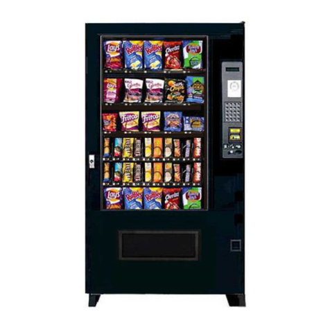
AMS
AMS SENSIT II Operation and service manual
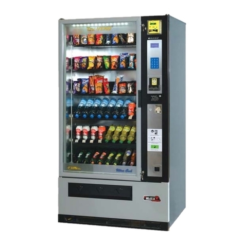
Elektral
Elektral TRU-VEND Maxi-Buffet Instructions for use & maintenance manual
Dixie Narco
Dixie Narco DN 55 Series Technical manual

