Bifarm AeroKit Manual
!
1!
Bifarm AeroKit - Installation and Setup Instructions ver. 1
The Bifarm AeroKit requires basic installation and setup before use. Please read and understand the
instructions below before beginning this process.
Required tools:
Medium Philips head screwdriver
Scissors
Ruler
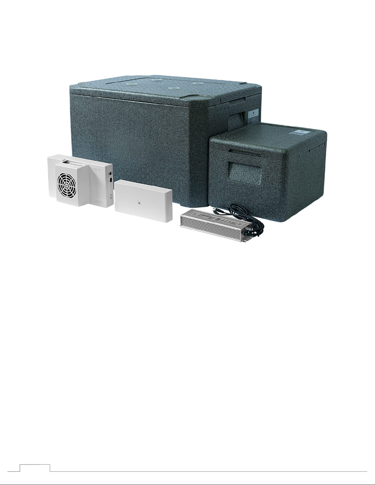
Please unpack and verify the various components from the parts list below:
Parts list:
Part 4 Main Controller
Part 7 Root Temperature Sensor
Part 8 Habitat Temperature and Humidity Sensor
Part 9 Power Supply
Part 14 Wire Harness
Part 15 Extension Cord for Level Meter
Part 16 Temperature Controller Unit Wire Extension
Part 19 Recycling Tube
Part 21 Tube Insulation
Part 22 Quick Connector Clips
!
2!
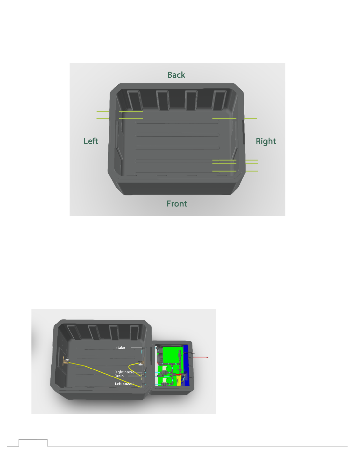
Orientate the root chamber correctly according to the following diagram:
§ The left side will have two capped ports
§ The right side will have five capped ports
Attaching the pressure system:
The pressure system is contained within the smaller EPP container. It connects to the root chamber
using four white tubes pressed through the root chamber wall using the pre-configured ports.
Diagram:

!
3!
Place each of the pressure tube assemblies through the correct port from the inside of the root
chamber.
From the back to the front on the inside right side of the root chamber:
First, place the intake tube through the back-most port right inside wall of the root chamber.
Next, the place the right nozzle tube through the next port, just to the front of the right nozzle.
Next, place the white tube portion of Part 19 - Recycling Tube (Drain) through the next port, just to
the front of the of the right nozzle tube.
Lastly, place the left side nozzle tube through the front-most port.
!
4!
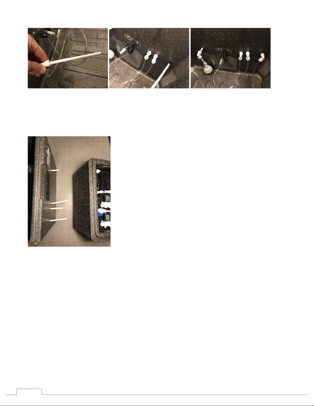
Connect the pressure control box to the root chamber.
Place the pressure box next to the root chamber. Line up the four ports with the four tubes extending
from the root chamber.
Note: the tube should line up exactly with the ports, if they do not change the orientation of the
pressure system box as you may be using the incorrect side.
Carefully thread the tubes into the ports and push the chamber and box together. Each for the four
tubes will be connected to their components using quick connectors inside the pressure box.
It is important that the connections are tight and secure. Follow the following steps when
connecting. Press the tube all the way into the fitting. Insert a blue locking clip and squeeze
firmly into place to secure the connection.
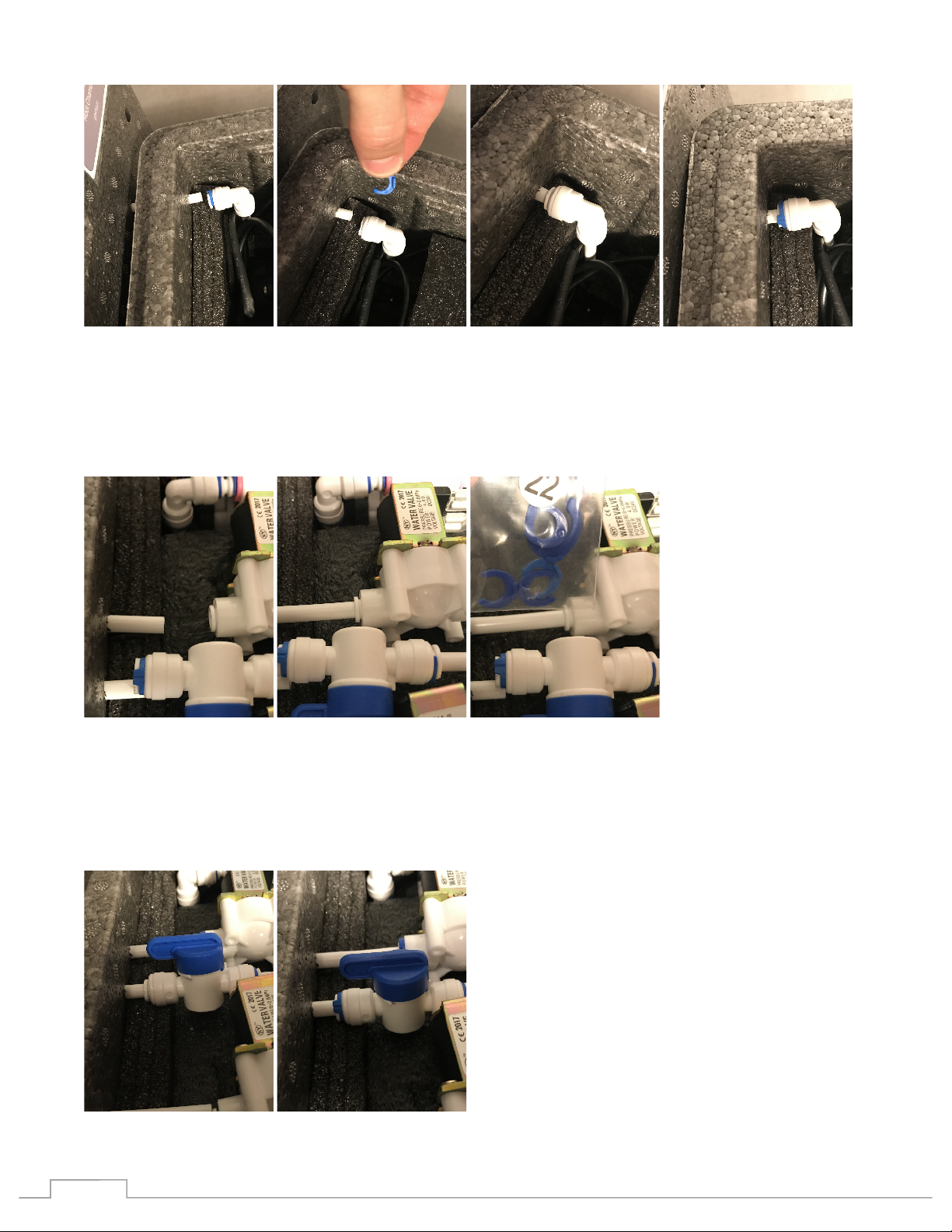
Secure each of the tubes:
1. Starting from the back, the nutrient intake tube.
• Remove the blue locking clip from the connector
• Press the tube firmly and completely into the connector
• Replace the blue locking clip
!
5!
2. Next the right nozzle tube
• Press the tube firmly and completely into the connector
• Place a small blue locking clip onto the connector, Part 22 – Quick Connector Clips.
3. Next the Recycling (Drain) Tube
• Remove the blue locking clip from the connector
• Press the tube firmly and completely into the connector
• Replace the blue locking clip

!
6!
4. Lastly the left side nozzle tube
• Press the tube firmly and completely into the connector
• Place a small blue locking clip onto the connector, Part 22 – Quick Connector Clips.
The pressure control box cables need to be extended outside of the box. There are four cables, one
for each of the two solenoids, one for the digital pressure sensor and one for the pump.
• For each of the cables extend the screw to the end cap
• Press each cables completely down under the lid lip where the wall has been cut according to
the photo.
• Replace the pressure control box lid
Attaching the Temperature Controller
Place the temperature controller on the stand.
• Orientate the stand onto the bottom of the controller

!
7!
Note: The temperature controller needs to be placed at the same level as the root chamber. Do no
place this unit elevated or lower than the root chamber.
Connect the temperature controller
First remove the caps covering the intake and output ports from the left side of the root chamber.
Connect the intake tube
• Using one of the two Tube Insulation (Part 21), feed the smaller inner tube into the back-most
port on the left side chamber from the outside
• Firmly attach from the inside the intake tube adapter connected to the red filter
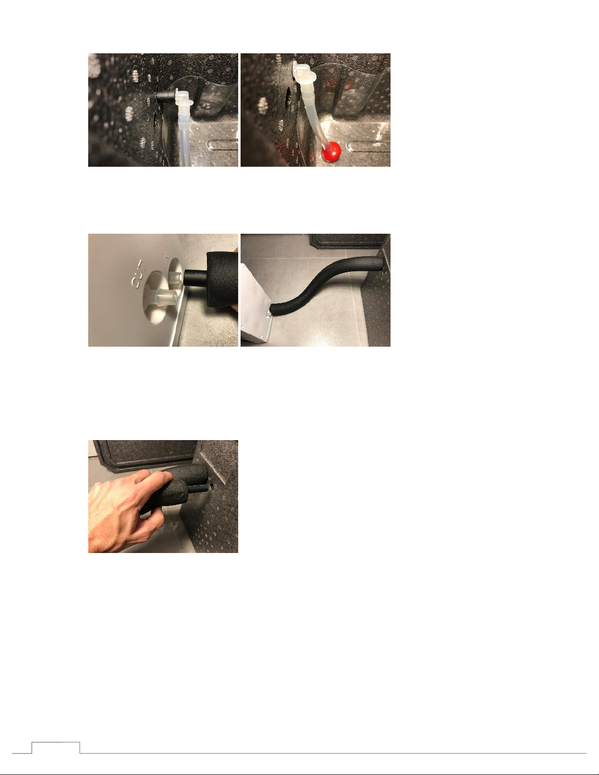
!
8!
• From the other side of the Tube Insulation, attach the inner tube to the Temperature
Controller’s IN adapter
Connect the output tube
• Using the remaining Tube Insulation (Part 21), feed the smaller inner tube into the remaining
port on the left side chamber from the outside
• Firmly attach from the inside the output tube adapter connected to the blue hand pump (Part
20)
!
9!
• From the other side of the Tube Insulation, attach the inner tube to the Temperature
Controller’s OUT adapter
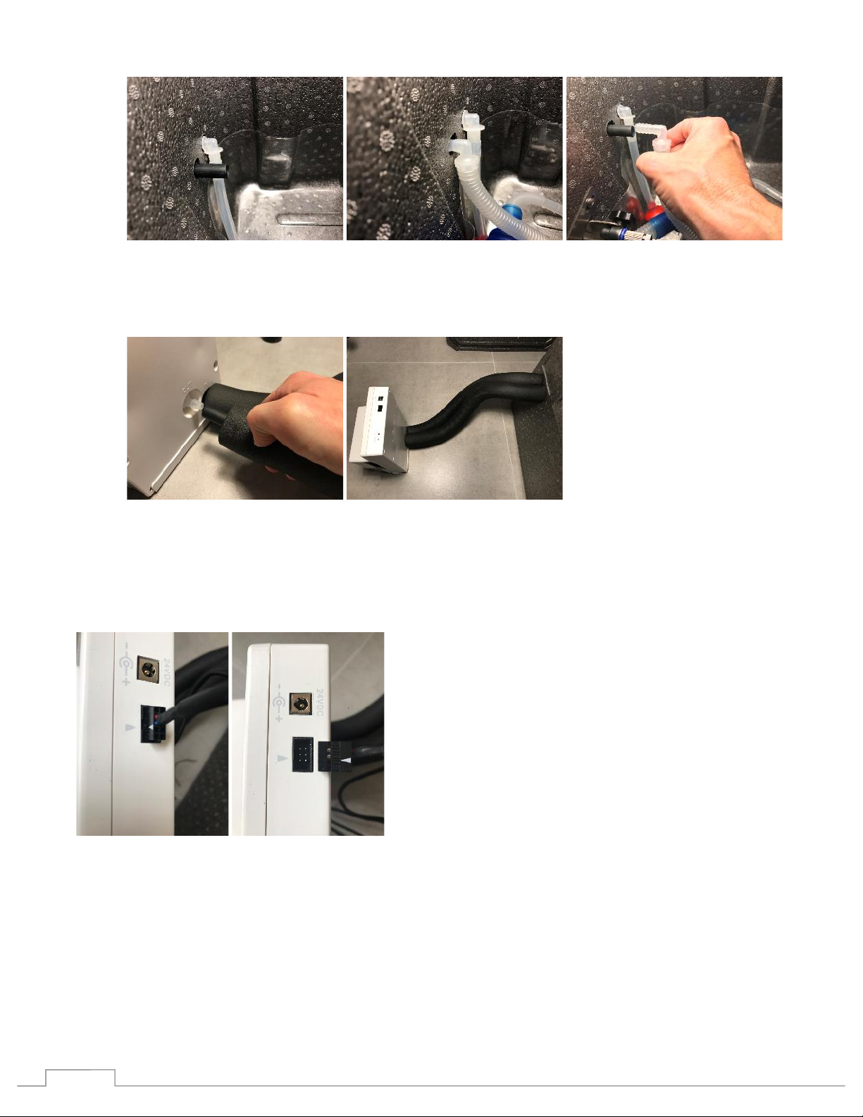
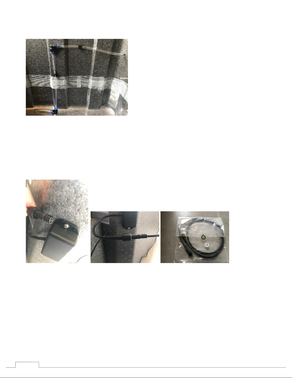
Connect the Temperature Controller Unit Wire Extension (Part 16). The cable fastener can be put in
backwards! Carefully line up the triangles on both the cable and the Unit to assure the correct
orientation when inserting the cable.
Install the nutrient level sensor
The pressure based sensor is used to determine the fill level of the reservoir.
Identify the Pressure Level Sensor:
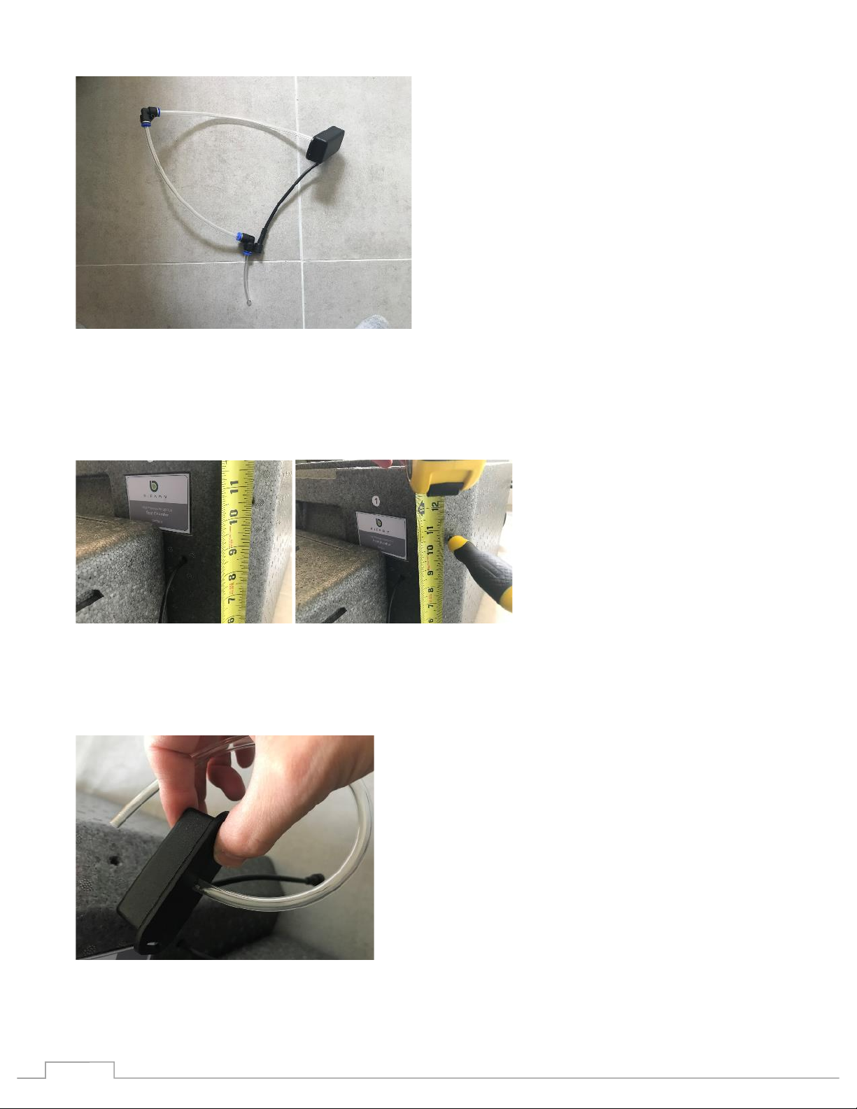
!
10!
This sensor will be installed on the back right corner of the root chamber.
There may be a port (hole) already in the correct location. If there is not you should make one. Using
a medium screwdriver (thinner than the tube used on the sensor) carefully and slowly punch a port
through the chamber wall 10.5 inches from the floor.
Separate the sensor tube from the elbow adapter closes to the sensor by disconnecting the tube that
extends from the sensor form the quick connect on the elbow. Press the blue ring of the adapter back
toward the corner of the elbow and pull out the tube.
Mount the sensor.
!
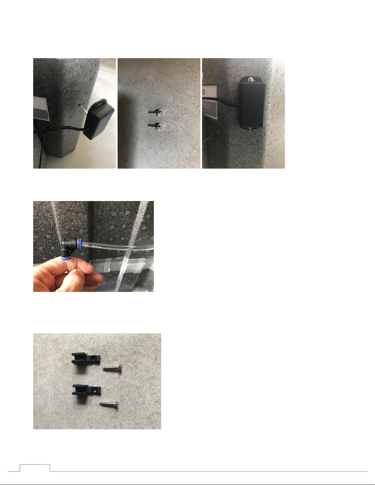
11!
From the outside, push the tube connected to the sensor through the port in the chamber
Use the correct screws (verify using photo) to secure the sensor to the corner of the chamber
From the inside, reconnect the tube into the adapter by inserting the tube pressing firmly.
The sensor tube need to be secured to the back chamber wall using the two tube clips provided.
Please carefully attach the tube to the wall the correct way to assure correct reservoir level readings.
!
12!
The elbow closes to the tube end needs to rest on the bottom of the root chamber. Follow the photo.
Note:
The first clip should secure the tube horizontally and the second vertically. The second elbow
adapter should be touching the bottom of the chamber and the end tube should be running parallel
to the bottom. Adjust the tube to match the photos.
Attach the Extension Cord for Level Meter (Part 15) to the sensor cable. Press cables together and use
screw to secure
Install the Root Temperature Sensor (Part 7)
• First remove the cap covering the sensor port from the right side of the root chamber

!
13!
• Insert the metal end of the sensor from the outside into the chamber port
• Press the sensor complete through the hole. Pull enough so that the tip of the metal touches
the inside bottom of the chamber.
Setting up the controller
Connect both the Wire Harness (Part 14) to the Main Controller (Part 4) matching Cable A to the Port
labeled A and the same for B.
Place the Main Controller on top of the pressure control box.
Note: The cable harness numbering is as followed:
From left to right on the controller.
First harness is A and counts down cables from 14 to 1
Second is harness B and counts down from 9 to 1
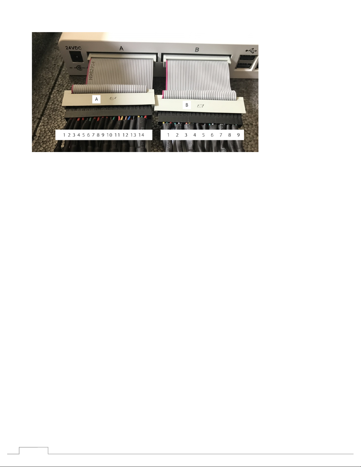
!
14!
Verify the number of pins match and the correct cable are being connected.
Firmly press cables together and use the screw lockdown to secure
Connect the following components to their correct cable on the Harness:
Name Cable Number Pins
Atomizer 1 connects to A 1 2
Atomizer 2 connects to A 2 2
Pressure Pump connects to A 5 4
Pressure Sensor connects to A 11 3
Temperature control unit connects to A 12 4
Root Temperature Sensor connects to A 13 3
AC Power Switch (light control) connects to B5 3
Temperature and Humidity Sensor (Part 8) connects to B8 3
Nutrient Level Sensor connects to B9 4
Note:
The cables coming out of the pressure box from the back to the front are the Pump, Pressure,
Atomizer 1 and 2
Setup the power supply
The power supply has two plugs. Connect one to the controller and one to the temperature manager.

!
15!
Status Light Key
Light status Operation mode
Fade in Booting
Solid On registered
Slow blink On not registered
Fast blink Identify unit
Fade out Maintenance
Cycle fast blink and solid Warning
Other manuals for AeroKit
2
Other Bifarm Farm Equipment manuals


Popular Farm Equipment manuals by other brands


Frontier
Frontier DH1276 Operator's manual

Landoll
Landoll Weatherproofer III 2310 Series Operator's manual

Amazone
Amazone Catros 12003-2TS Operator's manual

burchland
burchland LGX Operator's manual

Maschio
Maschio COBRA 00553051 Use and maintenance / spare parts

Gaspardo
Gaspardo Primo E2 Use and maintenance