Big Daishowa SPEED FINISHER User manual
この度は、 スピードフィニッシャーをお買い求めいただき誠にありがとうございます。ご使用前にあたっては必ず本書を
お読みいただき、ご使用される方がいつでも見ることができる場所に必ず保管してくださいますようお願いいたします。
スローアウェイチップの取り付け方
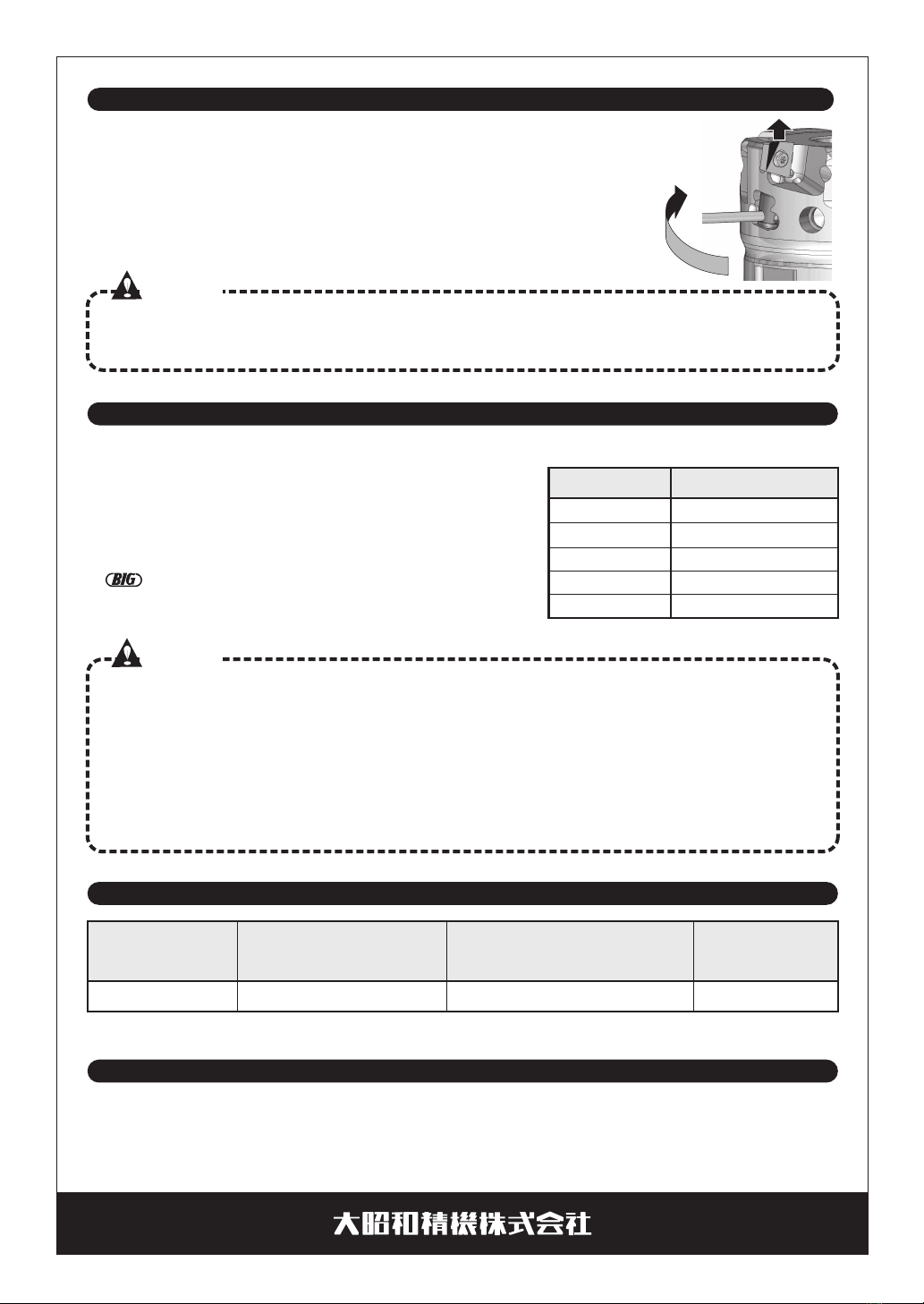
チップセット前にチップ着座部にエアーを吹
き付け、異物を取り除いてください。
レンチ(2mm 六角レンチ等)の先端をリフ
トナットの穴に差し込み、リフトナットを反
時計回りに回し、リフトスクリュをチップ座
面より少しだけ下げてください。
1.
2.
3.
4.
5.
チップの背面、側面をウエス等で丁寧に拭いてください。
チップをチップ座面に軽く押し付けながら、クランプスクリュを推奨締付けトルク1.0N
・
mで締め付けてください。
チップ座面に隙間が無いことをご確認ください。
・付属または純正のクランプスクリュ以外は使用しな
いでください。
・
チップ交換時は刃先で手を切らないよう注意してください。
・チップクランプスクリュとレンチは消耗品ですので
定期的に交換してください。
・先端の痛んだレンチ、穴の痛んだスクリュは使用し
ないでください。
リフトスクリュを下げすぎると、リフトナットの穴にレンチの先端が挿入できなくなることがありますので、
ご注意ください。
取扱説明書
スピードフィニッシャー
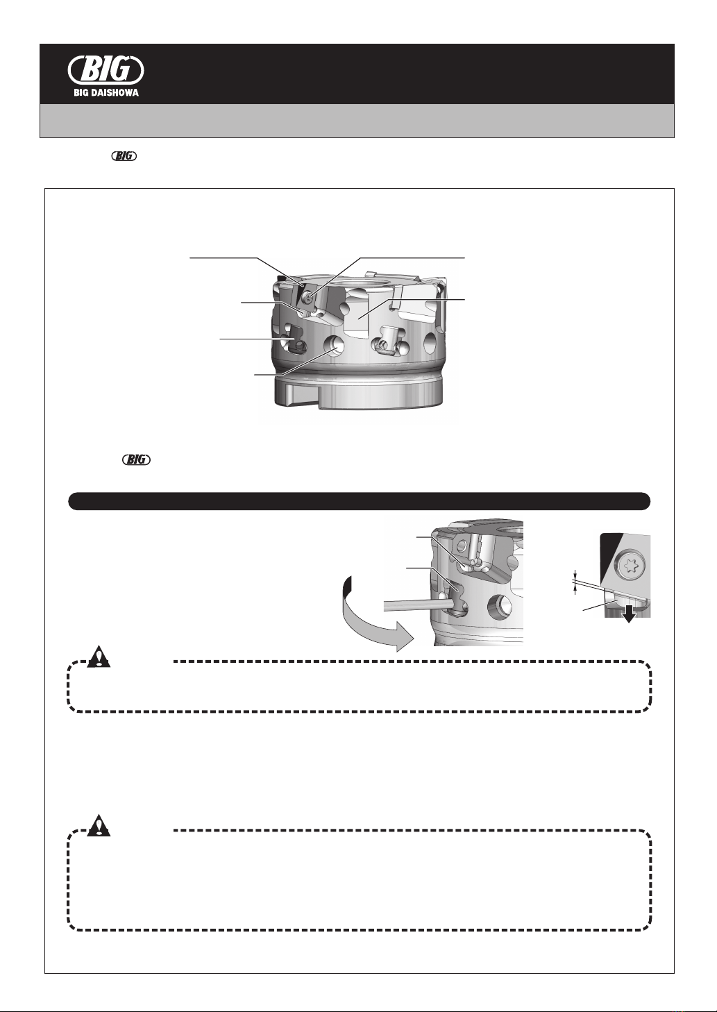
■各部の名称
ご注意
ご注意
リフトスクリュ
リフトナット
回転数12,000min-1以上でご使用の場合、カッタをアーバに取り付けた状態でのバランス調整を
にご依頼ください。
チップ チップクランプスクリュ
刃先割り出し溝
「PLプリセッタ」をご使用の際、
刃先の割り出しに使用。
リフトスクリュ
リフトナット
バランス調整ネジ穴
(バランス調整時に使用)
リフト
スクリュを
少し下げる
No.0718
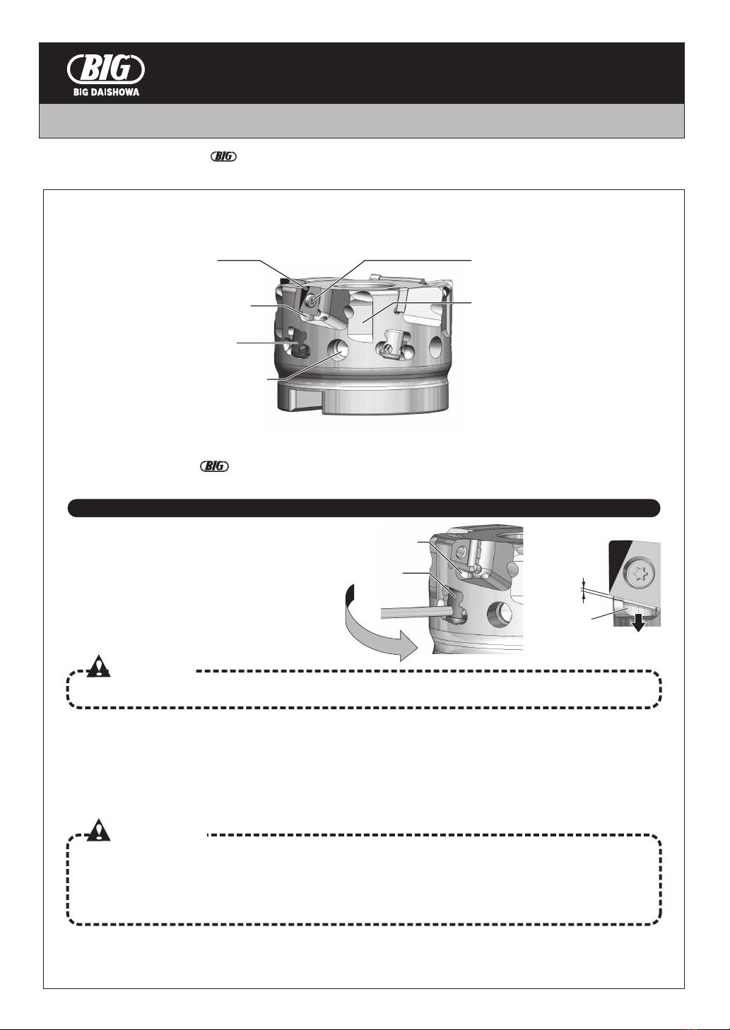
刃先の調整方法
切削に関して
スペアパーツ
スローアウェイチップの再研磨について
1.
2.
3.
プリセッタ上で最も刃先高さの高いチップを見つけてください。
最も高いチップのリフトナット・スクリュにテンションを与え固定するために、
リフトナットを時計回りに回し、チップを少し持ち上げます。
目安としては刃先が5μmほど持ち上がる程度です。
2. の刃先高さを目標に他のチップも同じ高さに揃えていきます。
そして全ての刃先高さが2μm以内に入るようにします。
刃先にプリセッターの測定子を急速に強い力で接触させると刃先が欠ける恐れがあるため、軽くゆっくり接触
させてください。また、測定子が刃先に接触している時にカッター本体を動かすと、刃先が欠ける恐れがある
ため、接触中は絶対に動かさないでください。
ご注意
ご注意
●標準切削条件は、「スピードフィニッシャー」カタログをご参照ください。
●鋳鉄を加工する場合、ウエット加工では熱亀裂の進行が早くチップ欠損
につながりますのでドライ加工でご使用ください。
アルミを加工する場合、溶着を防ぎ良い仕上げ面を得るために水溶性
切削油の使用をお奨めします。
●フェイスミルアーバには、センタースルー対応で高精度な
FMH型アーバを推奨します。
●最高許容回転数以上での使用は絶対にしないでください。
●チップの再研磨は1回(再研磨代0.2mm)まで可能ですが、刃先の磨耗量や欠けが大きい場合は、再研磨が不可能と
なりますので、早めの再研磨をお勧めします。
●同じカッタに新品と再研磨品のチップを混在させて使用しないでください。
φ50、φ63
φ80
φ100
φ125
φ160
カッタ径 最高許容回転数
20,000min-1
16,000min-1
12,800min-1
10,200min-1
8,000min-1
・刃数を減らしての加工や、突き出しの大きいアーバ
を使用する場合、バランス調整をせずに高速回転で
カッタを使用しないでください。
・不適切な切削条件での加工は行わないでください。
・剛性、馬力の十分な機械でご使用ください。
・ぶつけるなど、本体に強い衝撃を与えた後は使用し
ないでください。
・工具は切削時高温になります。使用直後に直接手で
触れると火傷の危険があります。
・切くずの飛散や誤った使用による工具の破損に対し
て、機械のカバーや安全メガネなどの保護具をご使
用ください。
・不水溶性切削油は火災発生の危険性がありますので
使用しないでください。
・チップの選定については「スピードフィニッシャー」カタログをご参照ください。
PL0705… S2506DS DA-T8LSN35
スクリュ10個
専用レンチ1本
( )
リフトスクリュ1個
リフトナット1個
( )
チップ型式 ドライバ型
レンチ
チ ッ プ ク ラ ン プ ス ク リ ュ セ ットリ フト ス ク リ ュ セ ット
■本社
東大阪市西石切町3丁目3-39〒579-8013
TEL.072(982)2312(
代)
FAX.072(980)2231
OPERATION MANUAL
SPEED FINISHER
Thank you for purchasing the SPEED FINISHER.
Please read these instructions before use and keep them where the operator may refer to them whenever neccessary.
HOW TO ATTACH INSERTS
Before attaching inserts, remove any foreign
particles on insert seats with compressed air.
Put the tip of a wrench(2mm Allen key) into the
hole on the lifting nut. Turn the lifting nut
counterclockwise and lower it slightly from the
insert seat.
1.
2.
3.
4.
5.
Wipe the side and back faces of the inserts thoroughly.
Tighten the screw with a tightening torque of 1.0N・m while lightly pressing the insert into its seat.
Make sure that there is no gap between the insert and the insert seat.
Do not use other insert clamping screws than the
original
or genuine new ones.
When exchanging an insert, be careful not to cut
your hands with its edges.
Periodically replace insert clamping screws and
wrenches that are consumable.
Do not use any wrenches or clamping screws that
are damaged on their tips or holes.
If the lifting screw is lowered too far, the tip of the wrench cannot be put into the hole of the lifting nut.
Insert Insert clamping screw
Index slot
: Used to index cutting edges on
“PL Presetter”.
Lifting screw
Lifting nut
Tapped hole for balancing
: Used to balance the cutter
with balancing screws.
Lifting screw
Lifting nut
When a cutter is used at a higher rotational speed than 12,000min-1,
request to balance the cutter attached to a toolholder.
NAMES OF PARTS
CAUTION
CAUTIONS
・
・
・
・
Lifting screw
Lower
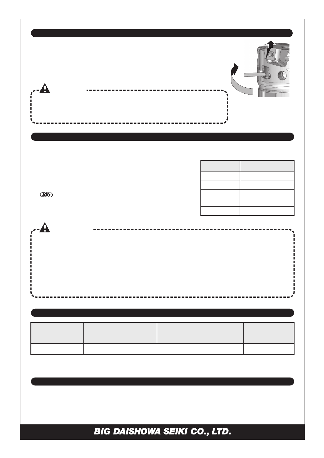
HOW TO ADJUST HEIGHT OF INSERTS
ABOUT CUTTING CONDITION
SPARE PARTS
REGRINDING OF INSERTS
Find the insert with the highest cutting edge on a presetter.
To set the lifting screw and nut of the first insert, turn the lifting nut clockwise
and lift the insert slightly (about 5μm).
Lift other inserts to the same height as the insert set in (2).
The height of all the inserts should be within 2μm.
If the stylus of a presetter is strongly and rapidly touching a cutting edge, the
cutting edge may chip. A stylus must touch the cutting edge lightly and slowly.
If the cutter is moved while the stylus is touching a cutting edge, the cutting edge
may chip. Do not move the cutter while the stylus touches a cutting edge.
Inserts can be reground 1 time (allowance 0.2mm). However, large wear and chipping on the
cutting edge makes it impossible to regrind. Regrinding in an early stage is recommended.
Do not mix new and reground inserts on the same cutter.
ø50, ø63
ø80
ø100
ø125
ø160
Cutterdia. Theallowable
max.speed
20,000min-1
16,000min-1
12,800min-1
10,200min-1
8,000min-1
In high rotational speed, do not use a cutter with
less inserts or long projection lengths without
balancing.
Do not apply inappropriate cutting conditions.
Do not use any cutters that have collided and
suffered a strong impact.
Use machine tools with sufficient rigidity and
horsepower.
・
・
・
・
Acutter becomes very hot during cutting.
Touching a cutter directly by hand soon after
cutting will lead to severe burns.
To prevent chips and broken tools from
scattering, install a safety cover on a machine
tool and use safety glasses.
Do not use insoluble oil that may cause fire.
・
・
・
Refer to the catalogue of “SPEED FINISHER” for insert selections.
CAUTION
Refer to the catalogue of “SPEED FINISHER” for standard cutting conditions.
If coolant is used in machining cast iron, thermal cracking on
the cutting edges tends to progress quickly.
Dry cutting is recommended for cast iron. In case of machining
aluminum, usage of coolant is recommended to prevent
built-up edge for better surface finish.
FMH face mill arbors with high accuracy and a center
through coolant holes are recommended.
Do not exceed the allowable maximum rotational speed.
●
●
●
●
●
●
CAUTIONS
PL0705… S2506DSLSN35
10pcsofscrews
1pcofwrench
()()
1pcofliftingscrew
1pcofliftingnut
Insert
DA-T8
Wrench
Insert clamping screw setLifting screw set
Table of contents
Popular Finisher manuals by other brands

Sankosha
Sankosha DF-100E-V3 instruction manual

AGCO
AGCO Glencoe SF4800 Operator's manual

Ricoh
Ricoh DDP70 Maintenance manual

Fayat
Fayat DYNAPAC F1000T T4f Operation & maintenance manual

Canon
Canon Perfect Binder D1 Service manual digest

Alliance Laundry Systems
Alliance Laundry Systems UL24A118 Installation & operation


DSB
DSB CW-350 operating instructions

Ricoh
Ricoh FS-108R user guide

Atlas Copco
Atlas Copco DYNAPAC Svedala Demag DF 115 C operation & maintenance

Bosch
Bosch GSI 14 CE Original instructions

Alliance Laundry Systems
Alliance Laundry Systems UD13F063 Installation and operation manual

AFINIA LABEL
AFINIA LABEL DLF-Series user manual