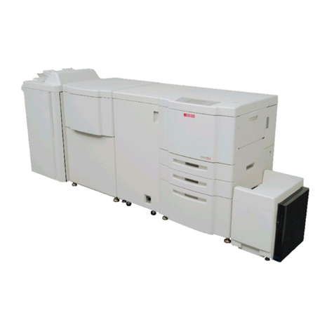
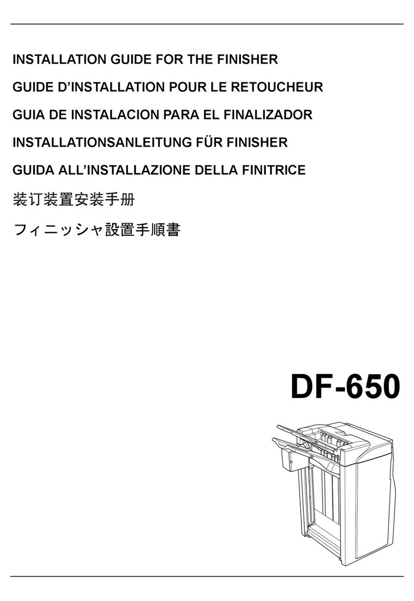
Ricoh DDP70 User manual

Standard Finisher
Maintenance
Manual
© 2005 Ricoh Printing Systems, Ltd.
May, 2005
N901402

© 2005 Ricoh Printing Systems, Ltd. All rights reserved.
No part of this document may be reproduced without the express permission of Ricoh
Printing Systems, Ltd.
The material in this document is for informational purposes and is subject to change
without notice. Ricoh Printing Systems, Ltd. assumes no responsibility for errors or
omissions in this document. No liability is assumed for any damages resulting from the
use of the information it contains.
NOTICE TO USER
In an effort to meet the demands of a rapidly changing technology, the manufacturer is
continually developing new features and functions to meet your changing printing or
printer needs. Please be sure to consult all manual updates or addenda when using
this product’s documentation.

i
DDP70 Finisher
Maintenance Manual
Copyright © 2005 Ricoh Printing Systems, Ltd.
N901402

ii DDP70 Finisher Maintenance Manual

i
Revisions
Page Rev. Machine Rev. Page No. (Contents) Date
00 - First Edition May, 2005

ii

Safety iii
Safety
Safety in Operation

iv DDP70 Finisher Maintenance Manual

i DDP70 Finisher Maintenance Manual
Contents
Chapter 1. Outlines. . . . . . . . . . . . . . . . . . . . . . . . . . . . . . . . . . . . . . . . . . . . . . . . .1-1
1.1. Characteristics . . . . . . . . . . . . . . . . . . . . . . . . . . . . . . . . . . . . . . . . . . . . . . . . . 1-1
1.2. Specifications. . . . . . . . . . . . . . . . . . . . . . . . . . . . . . . . . . . . . . . . . . . . . . . . . . 1-1
1.3. Configurations . . . . . . . . . . . . . . . . . . . . . . . . . . . . . . . . . . . . . . . . . . . . . . . . . 1-3
Chapter 2. Safe Handling of the Finisher . . . . . . . . . . . . . . . . . . . . . . . . . . . . . . .2-1
Chapter 3. General Information . . . . . . . . . . . . . . . . . . . . . . . . . . . . . . . . . . . . . . .3-1
3.1. Maintenance Precautions . . . . . . . . . . . . . . . . . . . . . . . . . . . . . . . . . . . . . . . . 3-1
3.2. Powering ON and OFF the Finisher . . . . . . . . . . . . . . . . . . . . . . . . . . . . . . . . 3-1
3.3. Tool Required. . . . . . . . . . . . . . . . . . . . . . . . . . . . . . . . . . . . . . . . . . . . . . . . . . 3-2
3.4. Motor & Solenoid Locations . . . . . . . . . . . . . . . . . . . . . . . . . . . . . . . . . . . . . . . 3-3
3.5. Switch & Sensor Locations . . . . . . . . . . . . . . . . . . . . . . . . . . . . . . . . . . . . . . . 3-5
3.6. Finisher Circuit Diagram . . . . . . . . . . . . . . . . . . . . . . . . . . . . . . . . . . . . . . . . . 3-7
Chapter 4. Preventive Maintenance . . . . . . . . . . . . . . . . . . . . . . . . . . . . . . . . . . .4-1
4.1. Periodic check and Cleaning by Customer Engineer . . . . . . . . . . . . . . . . . . . 4-1
4.2. Parts for Periodical Replacements and Frequencies by Customer Engineer . 4-2
4.3. Procedure of Replacing the Parts for Periodical Replacement . . . . . . . . . . . . 4-3
4.3.1. Replacing the Middle Sponge Roller . . . . . . . . . . . . . . . . . . . . . . . . . . . . 4-3
4.3.2. Replacing the Sponge Roller . . . . . . . . . . . . . . . . . . . . . . . . . . . . . . . . . . 4-5
4.3.3. Replacing the Paper Exit Roller . . . . . . . . . . . . . . . . . . . . . . . . . . . . . . . . 4-6
4.3.4. Replacing the Stapler . . . . . . . . . . . . . . . . . . . . . . . . . . . . . . . . . . . . . . . . 4-8
4.3.5. Replacing the Tray Up-down Motor . . . . . . . . . . . . . . . . . . . . . . . . . . . . 4-10
4.3.6. Replacing the Conveyance Roller A and Pulley/F . . . . . . . . . . . . . . . . . 4-11
4.3.7. Replacing the Conveyance Motor (M1) . . . . . . . . . . . . . . . . . . . . . . . . . 4-12
4.3.8. Replacing the Conveyance Motor (M7) . . . . . . . . . . . . . . . . . . . . . . . . . 4-13
4.3.9. Replacing the Grip Solenoid. . . . . . . . . . . . . . . . . . . . . . . . . . . . . . . . . . 4-14
4.3.10. Replacing the Paper Exit Opening Solenoid . . . . . . . . . . . . . . . . . . . . 4-15
4.3.11. Replacing the FS-104H P/K . . . . . . . . . . . . . . . . . . . . . . . . . . . . . . . . . 4-16
4.3.12. Replacing the Bearing Parts [Shaft holder (G8501088 / N421817),
Metal and Shaft holder (G8501064 / N421793)] . . . . . . . . . . . . . . . . . 4-17
Chapter 5. Troubleshooting . . . . . . . . . . . . . . . . . . . . . . . . . . . . . . . . . . . . . . . . . .5-1
5.1. Troubles . . . . . . . . . . . . . . . . . . . . . . . . . . . . . . . . . . . . . . . . . . . . . . . . . . . . . . 5-1
5.1.1. Abnormal stacking . . . . . . . . . . . . . . . . . . . . . . . . . . . . . . . . . . . . . . . . . . 5-1
5.1.2. Stapling failure . . . . . . . . . . . . . . . . . . . . . . . . . . . . . . . . . . . . . . . . . . . . . 5-3
5.1.3. Staple position failure . . . . . . . . . . . . . . . . . . . . . . . . . . . . . . . . . . . . . . . . 5-4
5.1.4. Alignment failure. . . . . . . . . . . . . . . . . . . . . . . . . . . . . . . . . . . . . . . . . . . . 5-4
5.1.5. Paper order is reverse . . . . . . . . . . . . . . . . . . . . . . . . . . . . . . . . . . . . . . . 5-4
5.1.6. Paper damage . . . . . . . . . . . . . . . . . . . . . . . . . . . . . . . . . . . . . . . . . . . . . 5-5
5.2. Error Code Indication. . . . . . . . . . . . . . . . . . . . . . . . . . . . . . . . . . . . . . . . . . . . 5-5
5.2.1. E009 SHIFT TRAY FULL 1
E00A SHIFT TRAY FULL 2 . . . . . . . . . . . . . . . . . . . . . . . . . . . . . . . . . . . 5-7
5.2.2. E019 LOW STAPLE (R)
E01A LOW STAPLE (F) . . . . . . . . . . . . . . . . . . . . . . . . . . . . . . . . . . . . . . 5-8
5.2.3. E03F FNS FRONT COVER OPEN . . . . . . . . . . . . . . . . . . . . . . . . . . . . 5-10
5.2.4. E064 to E068 PAPER ON PAPER PATH 14 to 18 . . . . . . . . . . . . . . . . . 5-11
5.2.5. E1D0 to E1D3 FNS 1 PAPER LEAD JAM 1 to 3
E1D8 FNS 1 PAPER LEAD JAM 5
E1D5 to E1D7 FNS 1 PAPER TRAIL JAM 1 to 4
E1D9 FNS 1 PAPER TRAIL JAM 5 . . . . . . . . . . . . . . . . . . . . . . . . . . . . 5-13
5.2.6. E260 FINISHER 1 CPU ERROR . . . . . . . . . . . . . . . . . . . . . . . . . . . . . . 5-16
5.2.7. E262 FINISHER 1 INCORRECT COMMAND

ii DDP70 Finisher Maintenance Manual
E264 FINISHER 1 ACT TIMEOUT
E266 FINISHER 1 DORMANT TIMEOUT
E268 FINISHER 1 BUSY TIMEOUT
E26C FINISHER 1 PRINT TIMEOUT . . . . . . . . . . . . . . . . . . . . . . . . . . 5-17
5.2.8. E26A FINISHER 1 ST EXIT SIGNAL ERROR. . . . . . . . . . . . . . . . . . . . 5-17
5.2.9. E2C1 STAPLER POS. ERROR . . . . . . . . . . . . . . . . . . . . . . . . . . . . . . . 5-18
5.2.10. E2C2 STAPLING ERROR
E2C3 STAPLING F ERROR
E2C4 STAPLING R ERROR . . . . . . . . . . . . . . . . . . . . . . . . . . . . . . . . 5-20
5.2.11. E2C5 STAPLER ROTATE ERROR . . . . . . . . . . . . . . . . . . . . . . . . . . . 5-21
5.2.12. E2C6 SHIFT TRAY TIMEOUT . . . . . . . . . . . . . . . . . . . . . . . . . . . . . . . 5-22
5.2.13. E2C7 ALIGNMENT PLATE POS. ERROR . . . . . . . . . . . . . . . . . . . . . 5-23
5.2.14. E2C8 SHIFT POS. ERROR . . . . . . . . . . . . . . . . . . . . . . . . . . . . . . . . . 5-24
5.2.15. E2C9 BELT POS. ERROR . . . . . . . . . . . . . . . . . . . . . . . . . . . . . . . . . . 5-25
5.2.16. E2CA PAPER EXIT OPENING POS. ERROR. . . . . . . . . . . . . . . . . . . 5-26
5.2.17. E2E5 FNS DRIVER . . . . . . . . . . . . . . . . . . . . . . . . . . . . . . . . . . . . . . . 5-26
Chapter 6. Disassembling, Assembling & Adjustment. . . . . . . . . . . . . . . . . . . . 6-1
6.1. Removal of the Cover Parts . . . . . . . . . . . . . . . . . . . . . . . . . . . . . . . . . . . . . . 6-1
6.1.1. Removal of the Rear Cover and the Top Cover . . . . . . . . . . . . . . . . . . . . 6-1
6.1.2. Removal of the Front Cover . . . . . . . . . . . . . . . . . . . . . . . . . . . . . . . . . . . 6-2
6.1.3. Removal of the Front Side Cover. . . . . . . . . . . . . . . . . . . . . . . . . . . . . . . 6-3
6.2. Removal of the Shift Unit Parts . . . . . . . . . . . . . . . . . . . . . . . . . . . . . . . . . . . . 6-4
6.2.1. Removal of the Shift Unit . . . . . . . . . . . . . . . . . . . . . . . . . . . . . . . . . . . . . 6-4
6.3. Removal of the Paper Conveyance Parts . . . . . . . . . . . . . . . . . . . . . . . . . . . . 6-6
6.3.1. Removal of the Sub-tray Paper Exit Roller . . . . . . . . . . . . . . . . . . . . . . . 6-6
6.3.2. Removal of the Stacker Entrance Roller . . . . . . . . . . . . . . . . . . . . . . . . . 6-8
6.4. Removal of the Paper Exit Parts . . . . . . . . . . . . . . . . . . . . . . . . . . . . . . . . . . 6-10
6.4.1. Removal of the Paper Exit Opening Unit . . . . . . . . . . . . . . . . . . . . . . . . 6-10
6.4.2. Removal of the Neutralizing Brush. . . . . . . . . . . . . . . . . . . . . . . . . . . . . 6-13
6.5. Removal of the Shift Tray Parts. . . . . . . . . . . . . . . . . . . . . . . . . . . . . . . . . . . 6-14
6.5.1. Removal of the Shift Tray. . . . . . . . . . . . . . . . . . . . . . . . . . . . . . . . . . . . 6-14
6.5.2. Removal of the Paper Exit Stopper Plate. . . . . . . . . . . . . . . . . . . . . . . . 6-15
6.5.3. Removal of the Up-down Stay . . . . . . . . . . . . . . . . . . . . . . . . . . . . . . . . 6-17
6.5.4. Removal of the Up-down Cable . . . . . . . . . . . . . . . . . . . . . . . . . . . . . . . 6-18
6.6. Removal of the Stacker Unit Parts . . . . . . . . . . . . . . . . . . . . . . . . . . . . . . . . 6-21
6.6.1. Removal of the Stacker Unit . . . . . . . . . . . . . . . . . . . . . . . . . . . . . . . . . 6-21
6.6.2. Removal of the Neutralizing Brush. . . . . . . . . . . . . . . . . . . . . . . . . . . . . 6-25
6.6.3. Removal of the Stapler Unit . . . . . . . . . . . . . . . . . . . . . . . . . . . . . . . . . . 6-26
6.7. Adjustment. . . . . . . . . . . . . . . . . . . . . . . . . . . . . . . . . . . . . . . . . . . . . . . . . . . 6-28
6.7.1. Adjusting the Sub-tray Gate . . . . . . . . . . . . . . . . . . . . . . . . . . . . . . . . . . 6-28
6.7.2. Adjusting the Paper Route Switching Gate . . . . . . . . . . . . . . . . . . . . . . 6-30
6.7.3. Adjusting the By-pass Gate . . . . . . . . . . . . . . . . . . . . . . . . . . . . . . . . . . 6-32
6.7.4. Adjusting the Shift Position . . . . . . . . . . . . . . . . . . . . . . . . . . . . . . . . . . 6-34
6.7.5. Adjusting the Open/Close Section of the Paper Exit Opening . . . . . . . . 6-35
6.7.6. Adjusting the Paper Exit Opening Solenoid . . . . . . . . . . . . . . . . . . . . . . 6-36
6.7.7. Adjusting the Paper Exit Opening Lower Guide Plate . . . . . . . . . . . . . . 6-38
6.7.8. Adjusting the Stacker Paper Exit Belt Tension . . . . . . . . . . . . . . . . . . . . 6-39
6.7.9. Adjusting the Alignment Plate Installation Position . . . . . . . . . . . . . . . . 6-40
6.7.10. Adjusting the Alignment Drive Timing Belt Tension . . . . . . . . . . . . . . . 6-41
6.7.11. Adjusting the Stapler Rotation Drive Section Installation . . . . . . . . . . . 6-42
6.7.12. Adjusting the Stapler 2 Position Staple Position . . . . . . . . . . . . . . . . . 6-43
6.7.13. Adjusting the Staple Slant of the Stapler 2 Position Mechanism . . . . . 6-44
6.7.14. Adjusting the Stapling Position for 1 Position Stapling. . . . . . . . . . . . . 6-45
6.7.15. Adjusting the Tension of the Stapler Move Timing Belt . . . . . . . . . . . . 6-46

Contents iii
Chapter 7. Theory of Operation . . . . . . . . . . . . . . . . . . . . . . . . . . . . . . . . . . . . . . .7-1
7.1. Center Cross Section. . . . . . . . . . . . . . . . . . . . . . . . . . . . . . . . . . . . . . . . . . . . 7-1
7.2. Drive System Diagram. . . . . . . . . . . . . . . . . . . . . . . . . . . . . . . . . . . . . . . . . . . 7-2
7.2.1. Paper Conveyance Drive . . . . . . . . . . . . . . . . . . . . . . . . . . . . . . . . . . . . . 7-2
7.2.2. Stacker Drive . . . . . . . . . . . . . . . . . . . . . . . . . . . . . . . . . . . . . . . . . . . . . . 7-3
7.3. Paper Conveyance Path . . . . . . . . . . . . . . . . . . . . . . . . . . . . . . . . . . . . . . . . . 7-4
7.3.1. Offset Mode . . . . . . . . . . . . . . . . . . . . . . . . . . . . . . . . . . . . . . . . . . . . . . . 7-4
7.3.2. Non-staple Mode . . . . . . . . . . . . . . . . . . . . . . . . . . . . . . . . . . . . . . . . . . . 7-5
7.3.3. Sub-tray Exit Mode . . . . . . . . . . . . . . . . . . . . . . . . . . . . . . . . . . . . . . . . . . 7-5
7.3.4. Staple Mode . . . . . . . . . . . . . . . . . . . . . . . . . . . . . . . . . . . . . . . . . . . . . . . 7-6
7.4. Conveyance Section . . . . . . . . . . . . . . . . . . . . . . . . . . . . . . . . . . . . . . . . . . . . 7-8
7.4.1. Construction . . . . . . . . . . . . . . . . . . . . . . . . . . . . . . . . . . . . . . . . . . . . . . . 7-8
7.4.2. Mechanism . . . . . . . . . . . . . . . . . . . . . . . . . . . . . . . . . . . . . . . . . . . . . . . . 7-8
7.4.2.1. Paper Conveyance . . . . . . . . . . . . . . . . . . . . . . . . . . . . . . . . . . . . . . 7-8
7.4.2.2. Paper Path Switching . . . . . . . . . . . . . . . . . . . . . . . . . . . . . . . . . . . . 7-9
7.4.2.3. Offset Operation . . . . . . . . . . . . . . . . . . . . . . . . . . . . . . . . . . . . . . . . 7-9
7.4.2.4. Stacker Unit. . . . . . . . . . . . . . . . . . . . . . . . . . . . . . . . . . . . . . . . . . . 7-11
7.4.2.5. Paper Exit Opening Unit . . . . . . . . . . . . . . . . . . . . . . . . . . . . . . . . . 7-11
7.5. Stapler Unit . . . . . . . . . . . . . . . . . . . . . . . . . . . . . . . . . . . . . . . . . . . . . . . . . . 7-14
7.5.1. Construction . . . . . . . . . . . . . . . . . . . . . . . . . . . . . . . . . . . . . . . . . . . . . . 7-14
7.5.2. Mechanism . . . . . . . . . . . . . . . . . . . . . . . . . . . . . . . . . . . . . . . . . . . . . . . 7-14
7.5.2.1. Stapling in One Place . . . . . . . . . . . . . . . . . . . . . . . . . . . . . . . . . . . 7-14
7.5.2.2. Stapling in Two Places . . . . . . . . . . . . . . . . . . . . . . . . . . . . . . . . . . 7-15
7.5.2.3. Staple Operation . . . . . . . . . . . . . . . . . . . . . . . . . . . . . . . . . . . . . . . 7-15

iv DDP70 Finisher Maintenance Manual

Outlines 1-1
M M L 0 0
Chapter 1. Outlines
1.1. Characteristics
70 pages/minutes high speed cut sheet finisher
Offset sorting and stapling with 3 places are available
Small size and easy paper handling
Easy change for staple cartridge
Applicable for variety size of paper
1.2. Specifications
Finishing speed 70 pages /minute (Letter, A4/LEF)
Dimensions 460(784*) x 1035 x 616 mm*: Include the shift tray
Weight 50 kg.
Paper A5 SEF*, B5 LEF, A4 LEF, A4 SEF,
-Size B4 SEF, A3 SEF, Letter SEF, Letter LEF,
8.5x12.4" SEF, Legal 13" SEF, Legal 14" SEF,
Ledger SEF, 12x18" SEF*
(SEF: Short Edge Feed LEF: Long Edge Feed)
* Non-staple mode only
-Weight Non-staple mode: 16 to 110(Index) lbs.
Sub tray exit mode: 16 to 42 lbs.
Staple mode: 16 to 34 lbs.
(Option for over
34 to 110(Index) lbs.)
Stacking mode Each stacking capacity is specified with xerography
and capacity80g/m2paper.
(1)Sub-tray exit mode
Maximum 200 sheets
(2)Non-staple / Offset mode
Maximum 2,000 sheets---- A4, Letter, B5
Maximum 1,500 sheets---- A3, B4, 8.5x12.4", Legal 13",
Legal 14", Ledger, 12x18"
Maximum 500 Sheets---- A5
(3)Staple mode
Number of
stapled sheets
Other than A3,
Ledger A3, Ledger
2 to 9 100 stacks 50 stacks
10 to 20 50 stacks 50 stacks
21 to 30 30 stacks 30 stacks
31 to 40 25 stacks 25 stacks
41 to 50 20 stacks 20 stacks
Table 1-1. Stacking Mode and Capacity

1-2 DDP70 Finisher Maintenance Manual M M L 0 0
Paper curl The allowable amount of paper curl is 10mm maximum.
Amount of offset 30 mm Note: Non-staple mode only
Stable type ofFlat clinch
clinch
Stapling capability Maximum 50 sheets (80 g/m2, 5.0 mm and below)
Stapling position 3 places
Stapling capacity 5,000 staples / cartridge
Power source 24V/5V (Supplied from the printer)
Temperature and (1) Operation
Humidity Temperature : 10 to 32 °C (50 to 89.6 °F)
Humidity : 20 to 80 %
Wet Bulb 26 deg.C (78.8 °F) max.
(2) Recommended condition
Temperature : 19 to 25 °C (66.2 to 77 °F)
Humidity : 40 to 60 %
Amount of
paper curl
5 sheets of printed paper
A
=
8
.
8
mm
B= 8.8 mm
C= 89.1 mm
D= 8.0 mm

Outlines 1-3
M M L 0 0
1.3. Configurations
The basic configuration of this finisher is as follows.
Finisher
Main Frame
Cover
Paper Conveyance
Shift Unit
Paper exit Unit
Shift Tray
Stacker Unit
Stapler Unit

1-4 DDP70 Finisher Maintenance Manual M M L 0 0

Safe Handling of the Finisher 2-1
M M L 0 0
Chapter 2. Safe Handling of the Finisher
This chapter describes the rules for safe handling of the finisher which must be strictly
observed by all maintenance personnel. Before conducting maintenance and inspec-
tion of the finisher, you must fully comprehend the following.
1. Before conducting maintenance or inspection, be sure to switch the power supply
OFF.
2. If it is absolutely necessary to work with the power turned ON, observe the follow-
ing:
3. Have one individual watch while the work is being performed so that that person
may switch OFF the power switch at anytime if necessary.
4. Never allow two individuals to work at the same time. It is very dangerous if a
drive part actuates suddenly.
(a) Never wear a ring, wristwatch, cuff-links, bracelet, metal fastener or any other
metallic objects.
(b) Be sure not to loosen or misuse screws. It is good practice to put a sheet of
paper under a portion where it is difficult to find small parts if dropped. Make it
a rule to replace screws back to their original place immediately after removal
of a part.
(c) Be particularly careful not to let a tool or a part drop into the finisher.
5. Whenever working on near a rotating part, stop the rotation and ascertain the
shape of it. The projection of a rotating part is very dangerous as it cannot be
seen when rotating. During work, pay attention to ties, sleeves, shirts and long
hair so that they may not be caught in the finisher. Always wear a working cap.
6. Before handling a movable part, make certain that it has completely stopped.
7. Wear eye protection whenever the following jobs are to be performed;
(a) To hammer the pins or rivet.
(b) To perform work using a hand drill.
(c) To mount or dismount a spring.
(d) To perform soldering or cutting wires.
(e) To clean parts.
8. Make sure that the power is OFF when replacing a PCB.
9. Care must be taken to store covers which are detached at a proper place to avoid
other people from tripping or stumbling, over them.
10. Do not leave tools in any unit, nor leave them on the floor. It is dangerous if they
are dropped into a unit and also it may cause other people to trip or slip on them
in another instance.
11. When you are going to move the finisher, first check to see that no personnel or
customers are around a dangerous position.
12. Carefully observe cautions itemized in this Maintenance Manual for your opera-
tions.
13. Be sure that nobody touches the finisher and carefully recheck if there is incorrect
wiring, incorrect connections, or tools remaining on the finisher before turning ON
the finisher.
14. Replace all the covers of the finisher back to their original position and make the
final checks without fail.
15. Before handing the finisher over to the customer, perform overall checking again.

2-2 DDP70 Finisher Maintenance Manual M M L 0 0

General Information 3-1
M M L 0 0
Chapter 3. General Information
This chapter describes the cautions and matter in general in relationship to the main-
tenance. It is particularly essential to read the following.
3.1. Maintenance Precautions
1. Thoroughly read through and understand the instructions to handle the finisher
safely as described in Chapter 2, “Safe Handling of the Finisher,” on page 2-1.
2. Do not place such parts as screws on the upper cover as these may fall off and
get astray.
3.2. Powering ON and OFF the Finisher
Figure 3-1. Location of the Main AC Power Switch
MAIN AC POWER
SWITCH
Finisher
Table of contents
Other Ricoh Finisher manuals

Ricoh
Ricoh SR5060 Quick start guide

Ricoh
Ricoh SR3270 Quick start guide

Ricoh
Ricoh A763 User manual

Ricoh
Ricoh SR3290 Quick start guide

Ricoh
Ricoh SR4110 Quick start guide

Ricoh
Ricoh DDP 92 User manual

Ricoh
Ricoh SR4120 Quick start guide

Ricoh
Ricoh FS-108R User manual

Ricoh
Ricoh SR400 User manual

Ricoh
Ricoh SR3300 Quick start guide