Sankosha DF-100E-V3 User manual

For your safety, please read this Instruction Manual carefully and
understand all instructions before starting operating of the
machine.
If at any time you have any questions, please do not hesitate to contact us.
DF-100E-V3
Instruction Manual
Instruction Manual

2
Product Specifications
Model DF-100E-V3
Power Single phase 230V 50/60Hz 10A
Air Consumption 5 liter / cycle
Steam Consumption 12kg / hour
Air Pressure 0.5MPa
Steam Pressure 0.5MPa
Air Pipe 1/4B
Steam Pipe Inlet:1/2B , Outlet:1/2B
Noise Level A Level : 72dB A Level : 82dB
Weight 165kg
Dimensions
Width × Depth × Height 1110mm×970mm×2170mm(Max)
Welcome
Thank you for choosing our DF-100E-V3 (Rotary Form Finisher).
This machine was delivered to you after thorough inspection at our plant.
Please read this manual carefully for proper usage of this machine.

3
Table of Contents
INSTRUCTION MANUAL.....................................................................................................1
Safety Guidelines ......................................................................................................4
Hazardous Area ........................................................................................................7
Safety Labels on the Machine................................................................................10
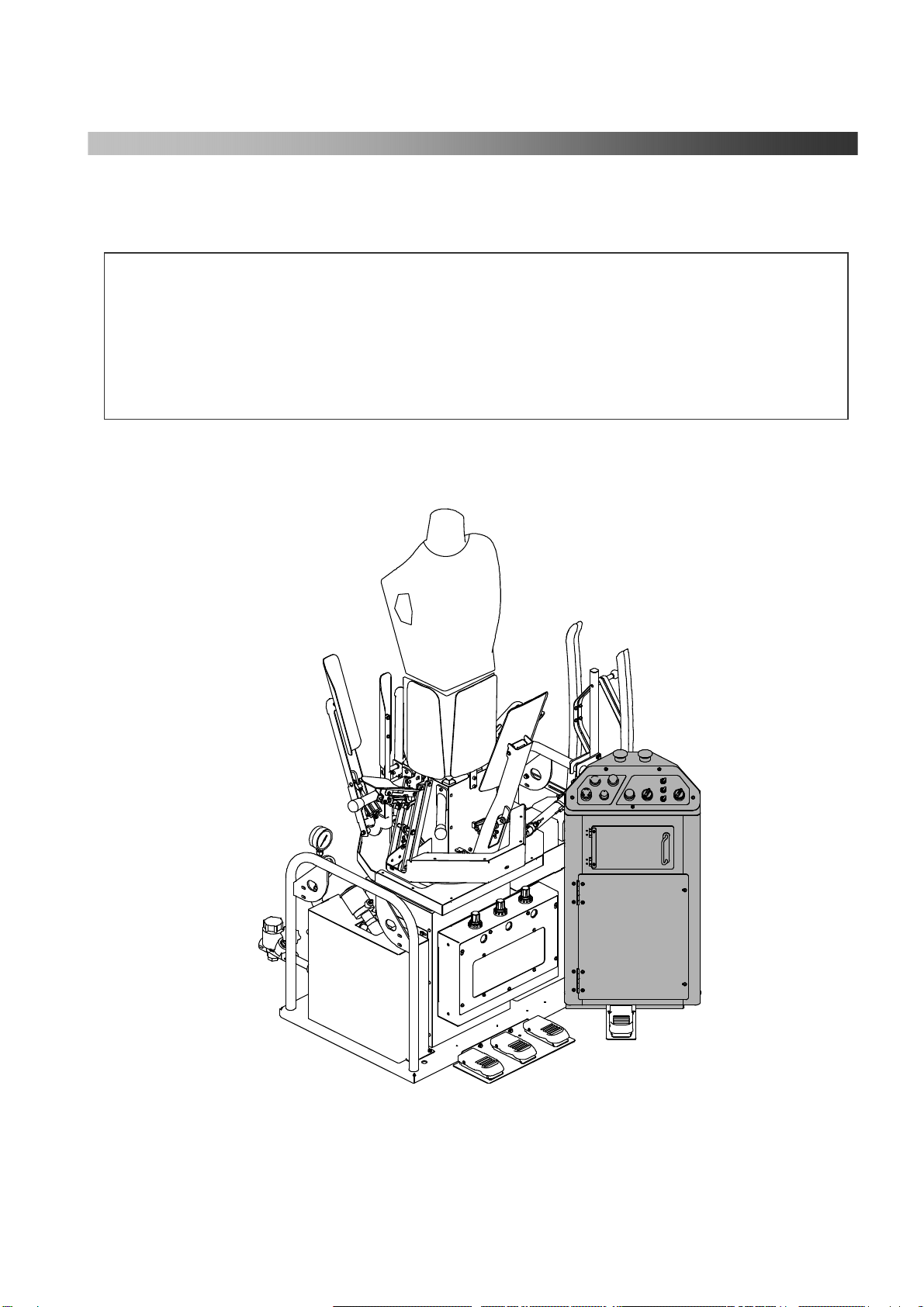
Parts Name.............................................................................................................. 11
Main device........................................................................................................ 11
Control box switch position ............................................................................... 12
Control Panel ..................................................................................................... 14
Foot pedal........................................................................................................... 15
Operation Procedures.............................................................................................16
Provide Air ......................................................................................................... 16
Provide Steam .................................................................................................... 17
Turn the Power On............................................................................................. 17
Select finish time................................................................................................ 17
Set the clothes on the body ................................................................................18
Turn the power off.............................................................................................. 21
Other Operations................................................................................................ 21
Cover/Pad Change Instruction..............................................................................22
1. Lower Body Cover setting ............................................................................. 22
2. Upper Body Cover setting.............................................................................. 23
3. Mat and cover setting of front and rear clamp / left and right side clamp ..... 23
Test Operation.........................................................................................................24
Operation Procedures......................................................................................... 24
Test Number List ............................................................................................... 25
Service Menu...........................................................................................................26
Trouble Shooting.....................................................................................................31
DAILY MAINTENANCE......................................................................................................35
Check Item List.......................................................................................................35
Check Item (Daily)..................................................................................................36
Check Item (Annual)..............................................................................................38
Maintenance Check List.........................................................................................39
SPARE PARTS LIST..............................................................................................................41
Front Diagram ........................................................................................................42
Rear Diagram..........................................................................................................44
Switch/Solenoid Valve Diagram.............................................................................46
Switch/Solenoid Valve Diagram.............................................................................48
Steam Piping Diagram............................................................................................50
Cover Diagram........................................................................................................52
ATTACHED DIAGRAM.......................................................................................................54

4
Safety Guidelines
Warning labels are placed on the machine in order to prevent an operator and others from injury, and to ensure proper
and safe operation. For most parts, labels are placed on the operational area of the machine.
Use this product safely upon reading this manual and understand the warning labels on the machine.
Please keep this manual as it will be needed in the future.
■ Please read the description of each warning label below. Each sign shows the degree of risk of injury or damage if
the manual and/or labels are not followed and the machine is misused.
DANGER This indicates a potentially hazardous situation which, if not
followed, may result in death.
WARNING
This indicates a potentially hazardous situation which, if not
followed, may result in serious injury.
CAUTION This indicates a potentially hazardous situation which, if not
followed, may result in minor or moderate injury.
■Rules are shown in the table below.
General Sign (for Alertness)
This is to alert the user to unspecified
caution, warning or danger.
General Sign (for Prohibition)
This is to alert the user to unspecified
prohibition.
Shock Hazard
This is to alert the user to a risk of
electric shock in certain circumstances.
Prohibition of Dismantling
This is to alert the user to a risk of
injury or shock if the indicated part is
dismantled.
Cut Hazard
This is to alert the user to a risk of cutting
hands or fingers by a cutter or others.
May cause physical handicap.
General Sign (for Compulsion)
This is to alert the user to unspecified
user’s action.
Burn Hazard
This is to alert the user to a risk of burn
from heat or steam.
Necessity to Ground
This is to indicate that the machine
must be properly grounded, using the
attached green wire.
Pinch Hazard
This is to alert the user to a risk of
pinching by rollers which may cause
permanent damage to extremities.
Rotation Hazard
This is to alert the user to a risk of
injury if rotating parts of the machine
are not properly covered with during
maintenance or operation.
Rotation Hazard
This is to alert the user to a risk of injury
if rotating parts of the machine are not
properly covered by during maintenance
or operation.
Sankosha cannot be held legally responsible for any injuries to operators or damages to the machine caused by
alterations to the machine or operations not described in the machine manual.

5
■ Installation
Installation and rigging of this product
should be performed only by an authorized
Sankosha distributor or by qualified
personnel who has read this manual.
Improper installation or rigging of this
machine may result in shock, injury or burn.
■ Shock Hazard
Do not put a finger or metal into the
machine or Control Box.
It may cause electric shock or
explosion.
■ Ground Connection
The green wire must be properly
grounded.
The electrical code must be conformed to
Single Phase 220V power.
Incorrect connection may cause electric shock.
■In case of flooding
Please call authorized personnel to inspect
and repair the machine if necessary.
It may cause electric shock.
■ Fire Hazard
Flammable articles such as gasoline, etc
should not be located near the machine.
It may cause fire or explosion.
■ Maintenance
Please call authorized service personnel.
Do not dismantle by yourself.
It may cause electric shock, injury,
fire or accident.
■ Shock Hazard
Do not touch the electric plug or switch.
It may cause electric shock.
■ Shock Hazard
Parts must not get wet when cleaning the
machine with water.
It may cause electric shock.
■Safety Instructions
・For your safety, please follow the
instructions below.
・ Only qualified trained personnel can operate the
machine.
・ Carefully read this Instruction Manual in full
before using the machine.
・ Make sure there is no one working near the
machine before beginning operation.
・ The machine should be operated individually at
all times.
・ Before conducting the proper maintenance,
always keep following instruction: close the air
and steam valves and release their residual
pressures.
■ Alteration Hazard
Do not improve or dismantle the machine.
It may cause accident.
■ Do not Use During Disrepair
Turn the main power and breaker switches
off in case of malfunctions.
Call authorized service personnel.
It may result in injury or further damage to
the equipment.
WARNING

6
■Maintenance of warning labels
The labels need to be cleaned and replaced if necessary.
It may cause an accident.
■Inside use only
The machine must be located inside the facility.
Do not place it in a damp or wet area.
It may cause an accident.
■Not in use abroad
Do not use the machine outside of designated countries.
It may cause fire due to different electrical supply.
■Cleaning
Both the main power switch and the breaker should be off when cleaning.
It may cause electric shock without power-off.
■Check and cleaning
Electric plugs and electric sockets need to be checked and cleaned periodically.
If you find any damage, call us or your Sankosha distributor.
Breakage can cause electric shock and fire.
■Adequate space
Adequate space around the machine should be secured for service and maintenance.
Potential injury to service/maintenance personnel may result.
CAUTION

7
Hazardous Area
Electrically Live Area
DANGER
Control box has terminals with lethal voltage.
-Only maintenance personnel can open the box.
-Turn off the power before opening the box.
Ignoring this warning will result in serious injury or death due to electrical shock.

8
Range of the Machine in Motion
WARNING
The machine has a certain range of motion.
Keep your hands away from the moving area during operation.
Before starting up or checking for maintenance, turn off the air and power first.
Ignoring this warning could result in serious injuries.

9
High Temperature Area
CAUTION
The machine has High Temperature Area.
Never touch these area during operation.
Do not also touch these areas for 30 minutes after the steam has been turned off.
Ignoring this warning may result in burns.
CAUTION

10
Safety Labels on the Machine
①
②
③
④ It may cause electric shock.
Before opening Control Box or maintenance, always turn the power off.
⑤ High pressure air!
Before maintenance, close air valve and drain residual pressure.
⑥ Surface is HOT!
Do not touch press head, piping and its surrounding area.
⑦ High pressure steam!
Before maintenance, close steam valve and drain residual pressure.
⑧ Cut hazard!
Keep hands away from the machine. Do not touch while operating.
⑨ Pinch hazard!
Keep hands away from the machine. Turn the power off during maintenance or cleaning.
⑩ Pinch hazard!
Keep hands away from the machine. Do not touch while operating.
⑪ Clean filter before operation.
⑫ Center Mark
Indicating the center of gravity of
the machine.
⑤
⑥
⑤
②
④(Inside
Control Box)
⑨
①
⑫
⑦
③
⑫
①
⑧
⑪
⑩
④
Make sure that each warning label is placed at
the location shown above. If any of the labels
is missing, damaged, or illegible, contact your
distributor to obtain a new one.

11
Parts Name
Main device
Side Clamp
Rotation Lever
(Manual)
Side Expander
Shoulder Expander Foot Pedal
Body down Foot Pedal
Body up Foot Pedal
Multi function Foot Pedal
Body
Front Clamp
Control Box
Control Panel
Operation Button
Solenoid Valve Box
Steam Gauge
Power Switch
Steam Inlet
Steam Outlet
Filter Regulator
Side Vents Clamp
Center Vents Clamp
Blower Motor
Filter
Inverter Box
Sleever Holder
Sleever

12
Control box switch position
① Power Switch
The switch is for the main power.
Black Button is for turning the Power ON. Red Button is for turning the Power OFF.
② Control Panel
You can change the setting, confirm the setting, or test each function.
Please see page 14 “Control Panel” for further details.
③ Emergency Stop Button
If you push this button, “E 1” will be displayed and the machine will return to first condition safely
whatever process you are in. In this time, buzzer will keep ringing. Turn the emergency button
clockwise to release the lock of the button. (Buzzer will stop and “---“will be displayed) If you push
the Reset button, machine will return to its normal condition.
④ Reset Button
When you push this button there are four different possible functions.
1. If you push this button after power supply ON, operation will be possible.
2. If you are in the foot pedal process, the machine will return to previous process.
3. If you are in auto operation, each timer will stop.
4. If you push this button when Emergency Stop Button works, the machine will return to its
normal condition.
⑤ Steam Button
Steam injects when you keep pushing this button.
※While in automatic mode, this button does not work.
⑥ Blower Button
If you push this button, the blower motor will turn on.
If you push it again, the blower motor will turn off.
※This button does not work while the finishing timer is on.
①
⑤
⑥
②
④
③⑦
⑧
⑨ ⑩ ⑪⑫⑬
⑭

13
⑦ Blower Power Dial
By turning this dial, you can change the blower power.
Turn the dial clockwise and the power will go up.
Turn the dial counterclockwise and the power will go down.
⑧ Body Rotation Button
This button makes the body rotate automatically.
⑨ Auto Start Button
If you push this button, this machine makes operation automatically whatever process you are
in. However shoulder expander, body up and down operations are not made automatically.
⑩ Timer Selection Switch
You can select Steam Timer and Blower Timer from following chart. The chart shows factory
initial setting of each timer.
Steam Timer
Blower Timer
Finishing Timer Laundry Button OFF
(Dry Mode)
Laundry Button ON
(Wet Mode)
・Short 4.0 sec. (Max.8 sec.) 10 sec. (Max.30 sec.) 10 min. (Max.30 min)
・Middle 6.0 sec. (Max.8 sec.) 20 sec. (Max.30 sec.) 20 min. (Max.30 min)
・Long 8.0 sec. (Max.8 sec.) 30 sec. (Max.30 sec.) 30 min. (Max.30 min)
*You can change each timer setting. Please see page 17.
*The blower timer shows “minutes” when the Laundry Button (next page ③) at the Control Box
is ON.
⑪ Mode Selection Switch
You can select following mode along with side expander function.
・Jumper Mode ········ Front clamp moves.
・Center Vents Mode ···· Center vents clamp and front clamp move and side expander opens.
・Side Vents Mode ······ Side vents clamp, front clamp move and side expander opens.
・No Clamp ··········· All clamps do not move.
⑫ Stretch Selection Switch
While this switch being ON, the body goes up for the time set at Volume (V4) after the automatic
process is done under the steam timer.
⑬ Side Clamp Selection Switch
When this button is turned on, side clamps move and clamp left and right sleeve.
⑭ Wide Side Vents Selection Switch.
When this switch is ON, the side vent clamps open left and right and you can process a larger size
jacket.

14
Control Panel
① Steam Timer Button (The light turns green when the button is ON.)
When this button is turned on, you can change the steam injection time with the ⑧”Dial”.
② Blower Timer Button (The light turns green when the button is ON.)
When this button is turned on, you can change the blower time with the ⑧”Dial”.
③ Landry Button (The light turns green when the button is ON.)
You can select time unit between minute and second for the blower timer.
When button is turned on, minute unit is selected and turned off, second unit is selected.
④ Test Button (The light turns green when the button is ON.)
Push this button to start the test operation for each function.
Please see page 24 "Test Operation" for further details.
⑤ Counter Clear Button
Push this button. "0" will blink at ⑨"Display Window". Push ⑥the "Enter Button".
You can reset the counter at "0". Push this button again. The window will show the garment
counter.
⑥ Enter Button (for Timer Remember) (The light turns green when the button is ON.)
Push this button after changing the timer setting for each mode. The time setting for each mode can
be saved.
⑦ Power Lamp
The red lamp is blinking if it is turned on. Also, it is blinking with Emergency Stop Button. It will
flash and go back to its original position with pushing the reset button.
⑧ Dial
This Dial can change all timers and select menu numbers.
⑨ Display Window
It shows the counter, timer with count down, error number menu number and etc…
①
④
②
⑤
③
⑥⑦⑧
⑨

15
Foot pedal
① Shoulder Expander Foot Pedal
When you press this pedal, Shoulder area will expand and you can adjust clothes.
Shoulder size returns when you press again.
② Body Down Foot Pedal
When you keep on pressing this pedal, body will move down.
③ Body Up Foot Pedal
When you keep on pressing this pedal, body will move up.
④ Multi Function Foot Pedal
When you press this pedal, you can advance operation process.
Process number will be displayed on the display window.
Process is Rear clamp(-1-) ⇒Front clamp(-2-) ⇒Side expander(-3-) ⇒Side Clamp(-4-)
⇒Auto operation.
①Shoulder Expander Foot Pedal
②Body Down Foot Pedal
③Body Up Foot Pedal
④Multi Function Foot Pedal

16
Run the machine where air can be supplied in a stable condition.
Use after-cooler or similar equipment to supply clean air at all times.
Operation Procedures
ProvideAir
Check whether air pressure is set at the required
level for main regulator and other regulators as
below.
①Main Regulator ・・・0.5MPa
②Body Rotation Cylinder ・・・0.3MPa
③Side Expander Cylinder ・・・0.2MPa
④Shoulder Expander Cylinder ・・・0.2MPa
Body Up/Down Cylinder
Low air pressure can cause a malfunction. If the pressure does not reach its standard level, set the
air pressure properly following the procedure below.
Check Point
Check compressor if the main air pressure does not reach 0.5MPa even after the above adjustment
③
①
②
④
Follow the procedure for proper operation.
Improper operation can cause mechanical failure or injury to operators.
CAUTION
■ How to adjust air pressure
1. Pull the adjustment knob up.
2. Turn the knob to adjust air pressure
Clockwise →Pressure will increase
Counterclockwise →Pressure will decrease
3. Push the knob down.
Attention!

17
Provide Steam
Check whether steam with the pressure at 0.5MPa or more can be supplied to the machine.
If the steam pressure does not reach the required level, it may adversely affect the garment finishing
quality. Always check whether the steam pressure meets its requirement.
It takes about 15 minutes until press heads heat up after steam is injected.
(It may vary depending on the season and the environment.)
Insufficient heat may adversely affect the garment finishing quality.
Turn the Power On
(1) The power is ON by pushing the black button at
the side of the control box.
→The power lamp at the control panel is blinking,
and show “- - -“on display.
(2) Push “Reset” button.
→The lamp will keep lit and it is available to operate.
Also, the display will change to counter.
Any operation is not available without
pushing the Reset button.
Select finish time
By using the Timer Selection Switch, you can select
the Steam Timer and the Blower Timer from 3
different modes: “Short”, “Middle”, and “Long”.
You can change each timer setting.
Please see page 13 ⑩Timer Selection Switch for
factor initial setting.
◎The setting change method of each timer
①Select a mode you want to use by Timer Selection Switch
②Push the Steam Timer Button or the Blower Timer Button.
→The green lamp on the upper right of selected button turns on, and the selected
Timer shows at the Display Window.
③Change Timer by turning the ”Dial” on the Control Panel.
・ Turn clockwise. Timer will increase.
・ Turn counterclockwise. Timer will decrease.
④Push the “Enter Button” to save the setting.
→Also, the display will change to counter.
・If you do not push the "Enter Button", it returns to the previous timer.
Please make sure to push the button if you want to save the new setting.
・If the Blower Timer setting is shorter than the Steam Timer setting, the Blower Timer
setting is automatically changed to the same as the Steam Timer setting.
Reset Button
Power Switch
Timer Selection Switch
Caution
Caution

18
Set the clothes on the body
≪In case of finishing center vents/side vents≫
(1) Turn the body back with rotation button (auto) or
rotation lever (manual).
It makes setting the garments easier.
(2) Change Mode Selection Switch according to the
garment you want to process.
(3) Set the garments on the body and straighten
shoulder position.
(4) Press the body up foot pedal.
→Body will move up. Adjust body to garment height
with body up and body down foot pedal.
(5) Straighten center and side vents positions and press
multi function foot pedal
→Rear side of the garments will be clamped.
(-1-is displayed )
*When the Wide Side Vents Selection Switch is ON,
the side vent clamps opens left and right. It is
useful for finishing a larger garment.
*You can change how to clamp the center vent and
side vent by using the DIP function in the Service
Menu (Please see 29page).
Rotation Lever (Manual)
Rotation Button (Auto)
Body down Foot Pedal
Body up Foot Pedal
・Make sure there is no one working near the machine before beginning operation.
・Beware of pinching hands or garment by moving part during the operation.
Wide Side Vents Selection Switch.
Multi Function Foot Pedal
Mode Selection Switch
Center Vents Clamp
Side Vents Clamp
Figure-1
CAUTION
Figure-2
Figure-3
Figure-4
Ti
p
s!

19
(6) Turn the body to the front side by using the rotation
button (auto), or rotation lever (manual)
(Please see the page 18 Figure-1.)
(7) Press the shoulder expander foot pedal.
→Expander will expand according to garments shoulder line.
Straighten shoulder line if it is needed.
(8) Straighten front placket and press the multi function pedal.
→Front side of the garments will be clamped.(- 2 - is displayed)
*If the setting is not correct, push the reset button.
The machine will return to its previous position.
(9) Press the multi function foot pedal.
→Side expander will expand according to garments line.
(- 3 -is displayed)
*If the setting is not correct, push the reset button.
The machine will return to its previous position.
(10) Press the multi function foot pedal.
→Left and right side will be clamped. (- 4 - is displayed)
*If the setting is not correct, push the reset button.
The machine will return to its previous position.
(11) Press the multi function foot pedal.
→The automatic operation will start.
*Auto operation procedure.
Steam Injection ⇒ Body going up (while Stretch Selection Switch being ON) ⇒ Steam/Blower
⇒ Blower (Dry) ・・・(Time of each process is counted in display window )
→When the finishing process is over, the front/rear clamp, the left/right clamp, and the body will stop
working.
(12) Press the Multi Function Foot Pedal twice while holding the both sides of the shoulder of the
garment.
→The first step releases the front/rear clamp and the left/right clamp. The second step makes the
body go down. You can then easily take off the garment.
*If you turn the DIP function “d 5” ON, all of the motions (releasing the front/rear clamp and
left/right clamp and the body going down) take place by using this only one step. (Please see
page 29)
Shoulder Expander Foot Pedal
Multi Function Foot Pedal
Tips!
Figure-5
Figure-6
Figure-7

20
≪In case of the jumper finishing≫
(1) Turn the body back with the rotation button (auto) or rotation lever (manual)
(It makes setting the garment easier.)
(2) Change the Mode Selection Switch to the “Jumper Mode”.
(3) Set garment on the body and straighten its shoulder position.
(4) Press Body up or Body down foot pedal.
→Body will move up. Adjust body to correct garment
height with Body up and Body down foot pedal.
(5) Turn the body to front side with the rotation button
(auto), or rotation lever (manual)
(6) Press the shoulder expander foot pedal.
→Shoulder area of the body will expand according to the
shoulder line. Straighten the shoulder position if it is needed.
(7) Press the multi function foot pedal.
→The front side will be clamped.(- 2 - is displayed)
*If the set is not correct, push reset button. The machine will return to its previous position.
(8) Press the multi function foot pedal.
→The automatic operation will start.
*Auto operation process.
Steam Injection ⇒Body going up (while Stretch Selection Switch being ON) ⇒Steam/Blower
⇒Blower (Dry) ・・・(Time of each process is counted in display window )
→When the finishing process is over, the front/rear clamp, the left/right clamp, and the body stop
working.
(9) Press the Multi Function Foot Pedal twice while holding the both sides of the shoulder of the
garment
→The first step releases the front/rear clamp and the left/right clamp. The second step makes the
body go down. You can then easily take off the garment.
*If you turn the DIP function “d 5” ON, all of the motions (releasing the front/rear clamp and
left/right clamp and the body going down) take place by using this the only one step. (Please see
page 29)
Body Down Pedal
Body Up Pedal
Multi Function Pedal
Shoulder Expander Pedal
Mode Selection Switch
Ti
p
s!
Table of contents