Big Daishowa HYDRAULIC CHUCK User manual
取扱説明書
ハイドロチャック
この度は ハイドロチャックをお買い求めいただき誠にありがとうございます。
ご使用にあたっては必ず本書をお読みいただき、ご 使 用される 方 が い つでも 見ることができる 場 所 に 必 ず 保 管してくださいますようお 願 いいたします 。
刃具の取り付け、取り外し
本体仕様
・
・
・
・
・
・
・
・
刃具シャンクはh6公差内のものをご使用ください。
刃具シャンクに打痕や傷等が無いことをご確認ください。
打痕がある刃具はチャックを損傷する恐れがありますので、絶対に使用しな
いでください 。
刃具のシャンク部に平取りがあるものは使用しないでください。
切刃で手を切る恐れがありますので、刃具の取り扱いにはウエス等をご使用ください。
刃具を挿入しない状態での空締めは、行わないでください。
内部を破損する恐れがあります。
最低把握長以上に刃具を挿入しないと内部を破損する恐れがあります。
ニッ ク 付 き ラ フィン グ エ ンド ミ ル は 、引っ張り勝手の力がかかりますので、
ハイドロチャックに適していません。その場合 ニューハイパワーミー
リングチャックやメガダブルパワーチャックをお奨めします。
刃具シャンク部にフレッティングが発生する場合、切削条件を下げてご使用
ください。フレッティングが発生した状態のままでご使用されますと、ホルダ
寿命が低下する場合があります。
ご注意
・
・
・
・
・
・
・
・
チャック 内 周 、刃具のシャンク部などについた傷や溶着物、切りくずなどは取り除き、汚れなどは清浄な灯油や脱脂剤を使ってウエスで拭き取ってください。
クランプスクリュは定期的にグリス(モービルXHP222相当)を塗布してください。
また、グリスを塗ってもクランプスクリュの動きが良くない場合には、クランプスクリュの交換をしてください。(有償)
油圧抜きネジは、透明な樹脂で封印されています。決して取りはずさないでください。
保管時には、錆を防ぐためにチャックを丁寧に拭き、防錆油を塗布してください。
回転中のチャックや刃具は大変危険ですので触れないでください。
加工中に刃具が折れた場合は、チャックの振れ精度とチャックに傷などがないか確認してください。
プルボルトの頭部に打痕傷や、胴部に曲がりのあるものは使用しないでください。
プルボルトは製のものをご使用いただき、2年ごとに交換してください。
ご注意
・
ストレートコレットをご使用の場合には、ストレートコレットのツバがチャック端面にあたるまで確実に挿入してください。
・ストレートコレットを使用すると、振れ精度や把握力が低下しますので、ご注意ください。
・PJC12はハイドロチャックではご使用いただけません。
ご注意
●取り付け
●取り外し
刃具シャンク部およびハイドロチャック内径を、きれいなウエス等を用
い清掃してください。内径の清掃には アルファワイパクリー ナ
(φ3〜φ1 2)、 TK ク リ ー ナ(φ13〜φ42)をお奨 めします 。
刃具取り付け時には刃具シャンクを下記の最低把握長以上に挿入してくだ
さい。刃具が入りにくい場合は、クランプスクリュをさらにゆるめてください。
クランプスクリュを付属のレンチにてネジ底が当たるまで締め付け、そ
れ以上の増し締めは行わないでください。
センタスルーでご使用の場合は、付属のプラグにシール材を塗布し、空
気抜き穴に栓を行ってください。
クランプスクリュを反時計方向に3〜7回転ゆるめると、刃具を抜き取
ることができます。
技術データ
チャック内径
mm
最低把握長
mm
使用温度
℃
把握力確認用
グリップバー型式
3S
4
4S
5S
6
6S
7
8
8S
9
10
10S
22
28
25
31
28
33
チャック内径
mm
最低把握長
mm
使用温度
℃
把握力確認用
グリップバー型式
11
12
12S
13
14
15
16
18
20
25
32
42
38
28
19
16
43
52
56
65
5〜505〜50
●確認の手順
●確認時期の目安
長期間のブランクをおいて使用する時。
刃具を約100回交換した時、または3ヶ月毎。
把握力の確認
スト レ ート コ レ ット に つ い て
取扱についてのご注意
高速加工について
安心してご使用いただくために、把握力のご確認を行ってください。
高精度ストレートコレットを使用できます。
10〜25℃の周囲温度で行ってください。
専用の把握力確認用グリップバー(別売)をチャック内径に最低把
握長以上差し込んでクランプスクリュを締め付けてください。
手で把握力確認用グリップバーを簡単に抜き取ることができるか
を お 試しくだ さ い 。
軽い力で抜き取れる場合は把握力が低下している恐れがあります。
この場合、ご使用にならないで、お買い求めの販売店を通じ当社に修理返却してください。
標準商品はプリバランスを行っていますが、高速回転で使用したり加工中
の振動が気になる場合にはバランス修正も行います。(有償)
また、ストレートコレット、調整ネジを使用される場合および刃具形状によっ
ては、若干バランスが悪くなることがありますのでご注意ください。
アジャストスクリュ(調整ネジ)について
刃具の突き出し長さの調整には、別売のアジャストスクリュをご使用ください。
内径 サイズ、呼び長さにより使 用できるアジャストスクリュが 異なります。
詳しくは、ハイドロチャックのカタログをご参 照ください。
また、BBT50シリーズにアジャストスクリュを取り付ける場合、弊社へお問
い合わせください。
※スーパ ースリムタイプはアジャストスクリュを使用できません。
No.0119PNK
端面給油タイプ
PJCストレートコレット
刃先給油タイプ
PSCストレートコレット
1
1
2
3
4
1
2
1
2
3
4
TSB 7
TSB 9
TSB11
TSB13
TSB14
TSB15
TSB16
TSB18
TSB20
TSB25
TSB32
TSB42
左ネジ(別売)
アジャストスクリュ
最低把握長 最低把握長
空気抜き穴
(2ヵ所)
空気抜き穴
(2ヵ所)
左ネジ(別売)
アジャストスクリュ
(アジャストスクリュとセット品)
ガイドスクリュ
クランプスクリュ
クランプスクリュ
※スーパースリムタイプはアジャストスクリュを使用できません。
(適合型式につきましてはカタログをご参照ください。)
TSB 6
TSB 4
TSB 5
TSB 3
TSB 8
TSB10
TSB12
把握力確認用
グリップバー
■本社
東大阪市西石切町3丁目3-39〒579-8013
TEL.072(982)2312(
代)
FAX.072(980)2231
33
38
36
HOW TO CLAMP AND UNCLAMP A CUTTING TOOL
SPECIFICATIONS
Use the shank of a cutting tool with the tolerance within h6.
Make sure that there are no dents and flaws on the shank of a cutting
tool. Never use the cutting tool, which has dents on its shank because
it is possible to damage the chuck.
Do not use a cutting tool, which has a flat on its shank except Weldon
shank (DIN 1835 B,).
Wrap a cutting tool with a waste securely, otherwise it is possible to
cut a hand with the cutting edge.
Never clamp HYDRAULIC CHUCK in the state that a cutting tool is not
inserted. Otherwise it is possible to damage the inside.
A cutting tool is not inserted beyond MIN. CLAMPING LENGTH, it is
possible to damage the inside.
A roughing endmill with nicks gives pulling force and is not suitable for HYDRAULIC
CHUCK. In this case, NEW Hi-POWER MILLING CHUCK is recommended.
For safekeeping, wipe the chuck carefully to prevent rust and apply
anti-corrosion oil.
If fretting corrosion is caused around the cutting tool shank, lower the cutting
parameters. Neglecting to do so could result in shorter service life of the holder.
·
·
·
·
·
·
·
·
·
CAUTION
When using a straight collet, insert the straight collet until its flange surely contacts with the end face of a toolholder.
When using a straight collet, be aware that runout accuracy and clamping force decrease.
PJC12 collet models cannot be used with the HYDRAULIC CHUCK.
·
·
·
Remove flaws, built-up metals and chips on the internal diameter and a shank of a cutting tool, and clean dirt by using a cloth with
kerosene or degreasing fluid.
Apply grease (MOBILE XHP222 or its equivalent) to the clamping screw periodically. If movement of a clamping screw is not good
even after grease is applied, exchange the clamping screw (with charge).
Do not remove a vent screw sealed with a transparent resin.
For safekeeping, wipe the chuck carefully to prevent rust and apply anti-corrosion oil.
Do not touch a toolholder and a cutting tool while they are rotating.
If a cutting tool is broken during cutting operation, check the runout accuracy of a toolholder and flaws on it.
Do not use the retention knobs that suffer hit flaws on the head part and the bent body.
A retention knob made by should be used and exchanged every 2 years.
·
·
·
·
·
·
·
·
TECHNICAL DATA
CHECKING CLAMPING FORCE
STRAIGHT COLLET
CAUTION (Handling with care)
HIGH SPEED CUTTING
Exclusive high-precision straight collets are available.
The standard products are pre-balanced. If vibrations at high
spindle speed are on your minds, post-balanced products are
available (with charge).
However, the maximum spindle speed is 20,000min-1.
When using a straight collet and a adjusting screw or depending
on a shape of a cutting tool, some balance may get worse.
ADJUSTING SCREW
In order to adjust the projection length of a cutting tool, an
adjusting screw sold separately is available.
Depending on the internal diameter and projection length of a
toolholder, the adjusting screw is different.
Refer to the catalogue of HYDRAULIC CHUCK.
When an adjusting screw is attached to the #50 taper models,
consult with .
※
Adjusting screw cannot be used with the Super Slim Type.
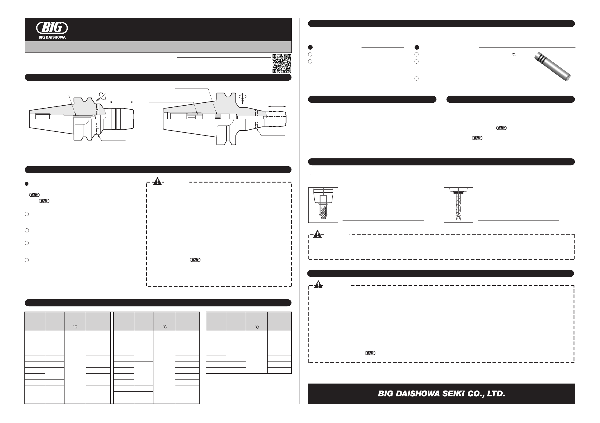
Nose coolant supply type Central coolant supply
(sold with adjusting screw)
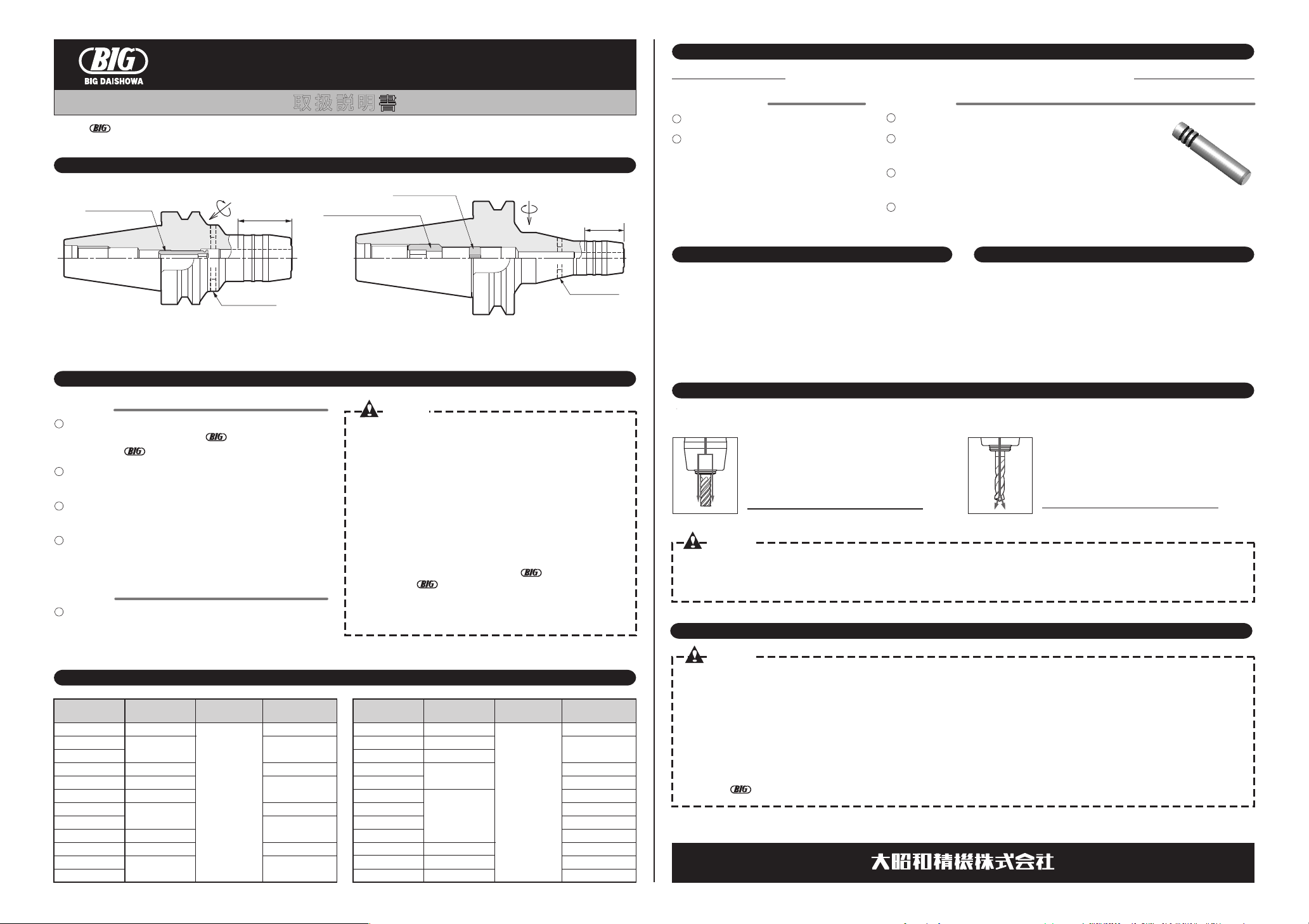
OPERATION MANUAL
Please read these instructions before use and keep them where
the operator may refer to them whenever necessary.
HYDRAULIC CHUCK
Adjusting screw
Left-handed screw
(sold separately)
Adjusting screw
Left-handed screw
(sold separately)
Clamping screw
Clamping screw
Minimum
clamping length Minimum
clamping length
Vent (2 places)
Vent (2 places)
Insert the cutting tool deeper than the min. clamping length
shown in the table below. Loosen the clamping screw
further if cutting tool is hard to insert into the chuck bore.
Using the accessory wrench, tighten the clamping screw to
the bottom of the thread. Do not tighten the screw further.
When coolant is supplied through the spindle, apply sealing
compound to the accessory screws and plug the vents.
Loosen the clamping screw 3 to 7 turns counterclockwise
and remove the cutting tool.
Clean the shank of a cutting tool and the internal
diameter of HYDRAULIC CHUCK with a clean cloth.
α
WIPER CLEANER(ø3
-
ø12),
and TK CLEANER (ø13
-
ø42) is recommended to
clean the internal diameter.
1
2
3
4
If the chuck is used after on use for a long time.
If a cutting tool is exchanged 100 times,
or every 3 months.
Check the clamping force in order to use safely.
The environmental temperature should be 10
-
25 .
Insert the exclusive GRIP BAR into the internal
diameter of the chuck beyond the minimum clamping
length and tighten CLAMPING SCREW.
Check whether
GRIP BAR
is easily pulled out. If so, it is
possible that the clamping force has dropped.
1
2
1
2
3
PERIOD OF CHECKING PROCEDURE OF CHECKING
CAUTION
CAUTION
※Adjusting screw cannot be used with the Super Slim Type.
※BCV shank models are compatible with coolant supplied through both the center and flange of the spindle.
(Please refer to the catalog for collet models.)
Clamping
Dia.
inch
Min.
clamping
length
inch
GRIP BAR model
for checking
clamping force
Operating
Temperature
.250
.375
.500
.625
.750
1.000
1.250
1.1
1.3
1.5
2.1
2.2
5
-
50
Clamping
Dia.
mm
Min.
clamping
length
mm
GRIP BAR model
for checking
clamping force
Operating
Temperature
Clamping
Dia.
mm
Min.
clamping
length
mm
GRIP BAR model
for checking
clamping force
Operating
Temperature
TSB .250
TSB .375
TSB .500
TSB .625
TSB .750
TSB1.000
TSB1.250
1.7
PJC COLLET PSC COLLET
※Jet-Through Type is not equipped with the vents.
GRIP BAR for
checking clamping force
OPERATION MANUAL DOWNLOAD SITE
http://big-daishowa.com/manual_index.php
3S
4
4S
5S
6
6S
7
8
8S
9
10
10S
22
28
25
31
28
33
11
12
12S
13
14
15
16
18
20
25
32
42
38
28
19
16
43
52
56
65
5
-
505
-
50
TSB 7
TSB 9
TSB11
TSB13
TSB14
TSB15
TSB16
TSB18
TSB20
TSB25
TSB32
TSB42
TSB 6
TSB 4
TSB 5
TSB 3
TSB 8
TSB10
TSB12
33
38
36
Other Big Daishowa Power Tools Accessories manuals

Big Daishowa
Big Daishowa TOOL MASTER User manual

Big Daishowa
Big Daishowa Mega Synchro MGT 6-d Series User manual

Big Daishowa
Big Daishowa ST LOCK User manual

Big Daishowa
Big Daishowa BBT40-AG90-13-120 User manual

Big Daishowa
Big Daishowa BASE MASTER MICRO User manual

Big Daishowa
Big Daishowa SMART DAMPER User manual

Big Daishowa
Big Daishowa PULLSTUD User manual


