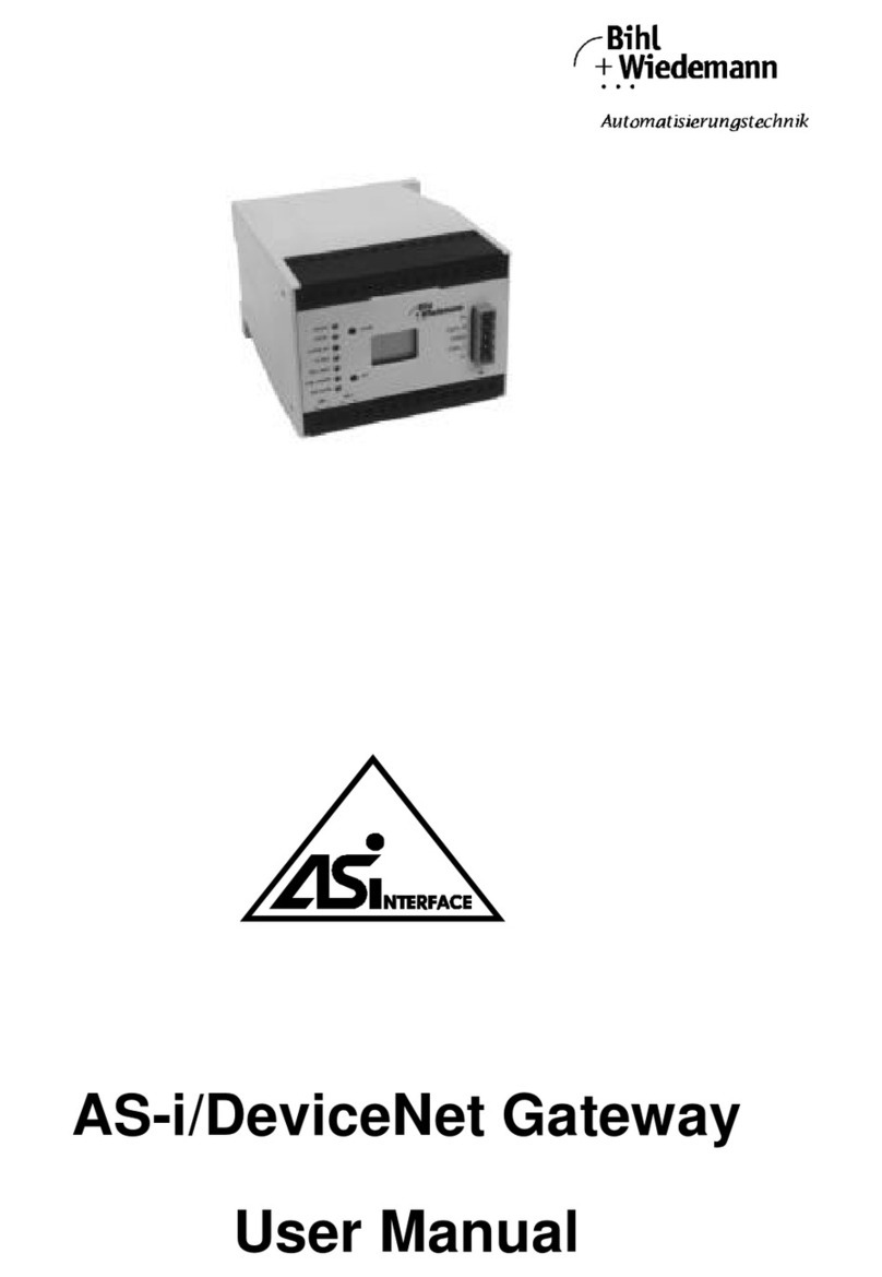
bihl+Wiedemann 1435 User manual

Specification 2.1
AS-i/CC-Link Gateway
User Manual


AS-i/CC-Link Gateway Table of Contents
Subject to reasonable modifications due to technical advances Copyright Bihl+Wied emann, Printed in Germany
Bihl+Wiedemann GmbH · D-68199 Mannheim · Phone +49-621-339960 · Fax +49-621-3392239 · Internet http://www.bihl-wiedemann.de
issue date 8.5.2003
1
Table of Contents
1 The Symbols Used .............................................................................. 7
2 Safety .................................................................................................... 9
2.1 Intended Use ...................................................................................................... 9
2.2 General Safety Information ............................................................................... 9
3 General Information .......................................................................... 11
4 Connections, Displays and Operating Keys ...................................13
4.1 Power Supply Concepts and AS-i Connection Techniques ........................ 13
4.1.1 Single Masters in IP65 ....................................................................................... 13
4.2 The CC-Link Interface ..................................................................................... 14
4.3 Display and Operating Elements ................................................................... 14
4.3.1 LEDs of the Single Masters ............................................................................... 14
4.3.2 Push-Buttons ..................................................................................................... 15
5 Operating the AS-i/CC-Link Gateway .............................................. 17
5.1 Master Start-Up ................................................................................................ 17
5.2 Configuration Mode ......................................................................................... 17
5.3 Protected Operating Mode .............................................................................. 18
5.3.1 Switching to Protected Operating Mode ............................................................ 18
5.3.2 Configuration Errors in Protected Operating Mode ........................................... 18
5.4 Assigning an AS-i Address in Configuration Mode ..................................... 19
5.4.1 Assigning a Slave Address ................................................................................ 19
5.4.2 Erasing the Slave Address ................................................................................ 19
5.5 Programming the Address in Case of Configuration Errors ....................... 20
5.5.1 Automatic Address Assignment ......................................................................... 20
5.5.2 Manual Address Assignment ............................................................................. 20
5.6 Setting the CC-Link Station Number and the Baudrate ............................... 21
5.6.1 Station Number .................................................................................................. 21
5.6.2 Baudrate ............................................................................................................ 21
5.7 Error Messages ................................................................................................ 21
6 Advanced Diagnostics for AS-i Masters ......................................... 23
6.1 List of Corrupted AS-i Slaves (LCS) .............................................................. 23
6.2 Protocol Analysis: Counters of Corrupted Data Telegrams ........................ 23
6.3 Off-line Phase on Configuration Errors (LOS) .............................................. 23
7 CC-Link User Interface ...................................................................... 25
7.1 Switching between the Mailbox and the Data Images ................................. 30
7.2 Switching to the IO Data Images .................................................................... 30
7.3 Switching to the Mailbox: ............................................................................... 30
8 Mailbox ............................................................................................... 31
8.1 Mailbox ............................................................................................................. 31

AS-i/CC-Link Gateway Table of Contents
Subject to reasonable modifications due to technical advances Copyright Bihl+Wied emann, Printed in Germany
Bihl+Wiedemann GmbH · D-68199 Mannheim · Phone +49-621-339960 · Fax +49-621-3392239 · Internet http://www.bihl-wiedemann.de
issue date 8.5.2003
2
8.1.1 Construction ....................................................................................................... 31
8.1.1.1 Values for command .......................................................................................... 32
8.1.1.2 Values for results ............................................................................................... 34
8.1.2 Mailbox commands ............................................................................................ 34
8.1.2.1 IDLE ...................................................................................................................34
8.1.2.2 READ_IDI .......................................................................................................... 34
8.1.2.3 WRITE_ODI ....................................................................................................... 35
8.1.2.4 Set_Permanent_Parameter (SET_PP) .............................................................. 36
8.1.2.5 Get_Permanent_Parameter (GET_PP) ............................................................. 36
8.1.2.6 Write Parameter (WRITE_P) ............................................................................. 36
8.1.2.7 Read Parameter (READ_PI) .............................................................................. 37
8.1.2.8 Store Actual Parameters (STORE_PI) ............................................................... 38
8.1.2.9 Set Permanent Configuration (SET_PCD) ......................................................... 38
8.1.2.10 Get Extended Permanent Configuration (GET_PCD) ........................................ 39
8.1.2.11 Store Actual Configuration (STORE_CDI) ......................................................... 39
8.1.2.12 Read Actual Configuration (READ_CDI) ........................................................... 40
8.1.2.13 SET_LPS ........................................................................................................... 40
8.1.2.14 GET_LPS ........................................................................................................... 41
8.1.2.15 GET_LAS ........................................................................................................... 42
8.1.2.16 GET_LDS ........................................................................................................... 43
8.1.2.17 GET_FLAGS ...................................................................................................... 43
8.1.2.18 SET_OP_MODE ................................................................................................ 44
8.1.2.19 SET_OFFLINE ................................................................................................... 45
8.1.2.20 SET_DATA_EX .................................................................................................. 46
8.1.2.21 Change Slave Address (SLAVE_ADDR) ........................................................... 46
8.1.2.22 Set Auto Address Enable (SET_AAE) ............................................................... 47
8.1.2.23 GET_LPF ........................................................................................................... 48
8.1.2.24 Write AS-i Slave Extended ID1 (WRITE_XID1) ................................................. 48
8.1.2.25 RD_7X_IN .......................................................................................................... 49
8.1.2.26 WR_7X_OUT ..................................................................................................... 49
8.1.2.27 RD_7X_OUT ...................................................................................................... 50
8.1.2.28 RD_7X_IN_X ..................................................................................................... 50
8.1.2.29 WR_7X_OUT_X ................................................................................................. 51
8.1.2.30 RD_7X_OUT_X ................................................................................................. 51
8.1.2.31 READ_ODI ......................................................................................................... 52
8.1.2.32 GET_DELTA ...................................................................................................... 52
8.1.2.33 WR_74_PARAM ................................................................................................ 53
8.1.2.34 RD_74_PARAM ................................................................................................. 53
8.1.2.35 RD_74_ID .......................................................................................................... 54
8.1.2.36 RD_74_DIAG ..................................................................................................... 54
8.1.2.37 Get_LPS, Get_LAS, Get_LDS, Get_Flags (GET_LISTS) .................................. 55
8.1.2.38 GET_LCS ........................................................................................................... 57
8.1.2.39 GET_LOS .......................................................................................................... 57
8.1.2.40 SET_LOS ........................................................................................................... 58
8.1.2.41 GET_TECA ........................................................................................................ 59
8.1.2.42 GET_TECB ........................................................................................................ 59
8.1.2.43 GET_TEC_X ...................................................................................................... 60
8.1.2.44 BUTTONS .......................................................................................................... 60
8.1.2.45 INVERTER ......................................................................................................... 61

AS-i/CC-Link Gateway Table of Contents
Subject to reasonable modifications due to technical advances Copyright Bihl+Wied emann, Printed in Germany
Bihl+Wiedemann GmbH · D-68199 Mannheim · Phone +49-621-339960 · Fax +49-621-3392239 · Internet http://www.bihl-wiedemann.de
issue date 8.5.2003
3
8.1.2.46 FP_PARAM ....................................................................................................... 61
8.1.2.47 FP_DATA .......................................................................................................... 62
8.1.2.48 READ_IDI_X ...................................................................................................... 62
8.1.2.49 READ_ODI_X .................................................................................................... 63
8.1.2.50 WRITE_ODI_X .................................................................................................. 64
8.1.3 Functional profiles ............................................................................................. 64
8.1.3.1 „Safety at Work“ List 1 ....................................................................................... 64
8.1.3.2 „Safety at Work“ Monitor Diagnosis ................................................................... 66
8.1.3.3 Integrated AS-i Sensors: Warnings ................................................................... 67
8.1.3.4 Integrated AS-i Sensors: Availability ................................................................. 68
8.1.4 Mailbox example ................................................................................................ 69
9 Appendix: The First Commissioning of AS-i .................................. 71
10 Appendix: Displaying the Figure Display ........................................ 73
11 We Are Interested in Your Opinion! ................................................. 75

AS-i/CC-Link Gateway Table of Contents
Subject to reasonable modifications due to technical advances Copyright Bihl+Wied emann, Printed in Germany
Bihl+Wiedemann GmbH · D-68199 Mannheim · Phone +49-621-339960 · Fax +49-621-3392239 · Internet http://www.bihl-wiedemann.de
issue date 8.5.2003
4

AS-i/CC-Link Gateway
Subject to reasonable modifications due to technical advances Copyright Bihl+Wied emann, Printed in Germany
Bihl+Wiedemann GmbH · D-68199 Mannheim · Phone +49-621-339960 · Fax +49-621-3392239 · Internet http://www.bihl-wiedemann.de
issue date 8.5.2003
5
Declaration of Conformity
according to 89/336/EEC and 73/23/EEC
Bihl+Wiedemann GmbH, Mannheim, hereby declares under its sole responsibility
that the products mentioned below are according to the listed harmonized stan-
dards or normative documents and (where neccessary) a component body has
been released.
Specification: AS-i/CC-Link Gateway, according to Specification 2.11
Article-no.: 1435
Applied harmonized Standards:
EN 50081-2
EN 61000-6-2
Applied national standards or normative documents:
AS-i Complete Specification (EN50295)
Prüfungsordnung für AS-i Master
Manufacturer: Bihl+Wiedemann GmbH
Date: 21.06.02 Bernhard Wiedemann

AS-i/CC-Link Gateway
Subject to reasonable modifications due to technical advances Copyright Bihl+Wied emann, Printed in Germany
Bihl+Wiedemann GmbH · D-68199 Mannheim · Phone +49-621-339960 · Fax +49-621-3392239 · Internet http://www.bihl-wiedemann.de
issue date 8.5.2003
6

AS-i/CC-Link Gateway The Symbols Used
Subject to reasonable modifications due to technical advances Copyright Bihl+Wied emann, Printed in Germany
Bihl+Wiedemann GmbH · D-68199 Mannheim · Phone +49-621-339960 · Fax +49-621-3392239 · Internet http://www.bihl-wiedemann.de
issue date 8.5.2003
7
1 The Symbols Used
This symbol warns the user of possible danger. Failure to heed this
warning can lead to personal injury or death and/or damage to
equipment.
This symbol warns the user of a possible failure. Failure to heed this
warning can lead to total failure of the equipment or any other con-
nected equipment.
This symbol gives the user important hints.

AS-i/CC-Link Gateway The Symbols Used
Subject to reasonable modifications due to technical advances Copyright Bihl+Wied emann, Printed in Germany
Bihl+Wiedemann GmbH · D-68199 Mannheim · Phone +49-621-339960 · Fax +49-621-3392239 · Internet http://www.bihl-wiedemann.de
issue date 8.5.2003
8

AS-i/CC-Link Gateway Safety
Subject to reasonable modifications due to technical advances Copyright Bihl+Wied emann, Printed in Germany
Bihl+Wiedemann GmbH · D-68199 Mannheim · Phone +49-621-339960 · Fax +49-621-3392239 · Internet http://www.bihl-wiedemann.de
issue date 8.5.2003
9
2 Safety
2.1 Intended Use
2.2 General Safety Information
The protection of operating personnel and the system against possi-
ble danger is not guaranteed if the control interface unit is not oper-
ated in accordance with its intended use.
The device may only be operated by appropriately qualified person-
nel in accordance with this operating manual.
Safety and correct functioning of the device cannot be guaranteed if
any operation other than that described in this operation manual is
performed.
The connecting of the equipment and any maintenance work to be
carried out with voltage applied to the equipment must only be per-
formed by appropriately qualified electrotechnical personnel.
In the case that a failure cannot be repaired, the device must be
taken out of operation and kept from inadvertently put back into
operation.
Repair work is to be carried out by the manufacturer only. Additions
or modifications to the equipment are not allowed and void the war-
ranty.
The operator is responsible for the observance of local safety stan-
dards.

AS-i/CC-Link Gateway Safety
Subject to reasonable modifications due to technical advances Copyright Bihl+Wied emann, Printed in Germany
Bihl+Wiedemann GmbH · D-68199 Mannheim · Phone +49-621-339960 · Fax +49-621-3392239 · Internet http://www.bihl-wiedemann.de
issue date 8.5.2003
10

AS-i/CC-Link Gateway General Information
Subject to reasonable modifications due to technical advances Copyright Bihl+Wied emann, Printed in Germany
Bihl+Wiedemann GmbH · D-68199 Mannheim · Phone +49-621-339960 · Fax +49-621-3392239 · Internet http://www.bihl-wiedemann.de
issue date 8.5.2003
11
3 General Information
This operating instruction is for use with the following devices of the Bihl+Wiede-
mann GmbH:
• AS-i/CC-Link Gateway, spec. 2.11 power supply A article-no. 1435
The AS-i/CC-Link Gateways serve to connect the Actuator-Sensor-Interface to the
CC-Link. A gateway represents the master for the AS-Interface and the slave for
the CC-Link.
All AS-Interface functions can be called via the CC-Link. The high protection cate-
gory IP 65 makes the device suitable for applications in the extreme industrial en-
vironments frequently encountered in the field. AS-Interface is connected using
the penetration technique of EMS (Electromechanical Interface). CC-Link is con-
nected with heavy gauge terminals and screw terminal blocks.
As with all Masters of Bihl+Wiedemann GmbH, commissioning, debugging and
setting up of the AS-i parameters can be accomplished with the use of two push-
buttons, the display and the LEDs directly on the device.

AS-i/CC-Link Gateway General Information
Subject to reasonable modifications due to technical advances Copyright Bihl+Wied emann, Printed in Germany
Bihl+Wiedemann GmbH · D-68199 Mannheim · Phone +49-621-339960 · Fax +49-621-3392239 · Internet http://www.bihl-wiedemann.de
issue date 8.5.2003
12

AS-i/CC-Link Gateway Connections, Displays and Operating Keys
Subject to reasonable modifications due to technical advances Copyright Bihl+Wied emann, Printed in Germany
Bihl+Wiedemann GmbH · D-68199 Mannheim · Phone +49-621-339960 · Fax +49-621-3392239 · Internet http://www.bihl-wiedemann.de
issue date 8.5.2003
13
4 Connections, Displays and Operating Keys
Devices in IP65:
The devices in IP65 have the terminals for CC-Link (screw terminals) and the push
buttons under the top of the housing to prevent liquids from entering. The AS-in-
terface is connected with the electromechanical interface with penetration tech-
nique developed for AS-i at the bottom of the housing.
4.1 Power Supply Concepts and AS-i Connection Techniques
An AS-i power supply has to be used which also supplies the AS-i master with po-
wer and can be connected to the AS-i cable like all the other AS-i components at
any place.
4.1.1 Single Masters in IP65
Every AS-i master and all the AS-i gateways in IP65 come with power supply A.
The AS-i master is connected to AS-i using the penetration technique of the elec-
tromechanical interface which is common with AS-i slaves as well.
AS-i Master
A
S-i power
AS-i
Slave
AS-i
Slave
AS-i
Slave
AS-i power
supply

AS-i/CC-Link Gateway Connections, Displays and Operating Keys
Subject to reasonable modifications due to technical advances Copyright Bihl+Wied emann, Printed in Germany
Bihl+Wiedemann GmbH · D-68199 Mannheim · Phone +49-621-339960 · Fax +49-621-3392239 · Internet http://www.bihl-wiedemann.de
issue date 8.5.2003
14
4.2 The CC-Link Interface
CC-Link gateway in IP65 can be connected to CC-Link with screw terminals inside
of the device. For that purpose the top of the housing has to be screwed off.
The device in IP65 is powered out of the AS-i line to which it is connected by the
electromechanical interface (penetration technique as it is used with AS-i slaves).
4.3 Display and Operating Elements
On the front panel of the AS-i/CC-Link gateway are ten light-emitting diodes, a two-
digit display and two push buttons.
With the devices in IP65 the push buttons are situated inside of the housing to avo-
id liquids from entering. The top of the housing has to be screwed off to operate
these push buttons.
4.3.1 LEDs of the Single Masters
PW The master's power supply is sufficient.
L RUN CC-Link Run LED
CC-Link interface communication active via the CC-Link interface.
L ERR CC-Link Error LED
A communication error occurs.
SD CC-Link Send Data LED
The CC-Link interface sends data.
RD CC-Link Receive Data LED
The CC-Link interface receives data.
CONF. ERR Configuration error
At least one configured slave is missing, or at least one detected
slave is not projected or for at least one projected and detected
slave the actual configuration data does not match the nominal
configuration data.
AS-i The AS-i circuit is sufficiently powered.
AS-I ACTIVE Normal operation active.
connection of CC-Link
interface on screw
terminal block
and arrangement on
circuit board:
1FG
Termination resistor:
To be removed if module is
not at the end of line
2SLD
3DG
4DA
5DB
6FG
7SLD
8DG
9DA
10 DB

AS-i/CC-Link Gateway Connections, Displays and Operating Keys
Subject to reasonable modifications due to technical advances Copyright Bihl+Wied emann, Printed in Germany
Bihl+Wiedemann GmbH · D-68199 Mannheim · Phone +49-621-339960 · Fax +49-621-3392239 · Internet http://www.bihl-wiedemann.de
issue date 8.5.2003
15
PRG ENABLE Automatic address programming enabled.
Exactly one slave is missing in protected operating mode. The
slave can be replaced by another slave of the same type with ad-
dress zero. The master addresses the new slave to the faulty ad-
dress and thus eliminates the configuration error.
PRG MODE The AS-i master is in configuration mode.
4.3.2 Push-Buttons
The push-buttons cause following:
mode Switching between the configuration mode and the protected operating
mode and saving the actual AS-i configuration as the nominal configu-
ration.
set Selection and assigning the address to a slave.
The detailled description is described in chapter 5.
By IP65 devices the push-buttons under the top of the housing to prevent liquids
from entering. For operation of the device the top of the housing is to be screwed
off.

AS-i/CC-Link Gateway Connections, Displays and Operating Keys
Subject to reasonable modifications due to technical advances Copyright Bihl+Wied emann, Printed in Germany
Bihl+Wiedemann GmbH · D-68199 Mannheim · Phone +49-621-339960 · Fax +49-621-3392239 · Internet http://www.bihl-wiedemann.de
issue date 8.5.2003
16

AS-i/CC-Link Gateway Operating the AS-i/CC-Link Gateway
Subject to reasonable modifications due to technical advances Copyright Bihl+Wied emann, Printed in Germany
Bihl+Wiedemann GmbH · D-68199 Mannheim · Phone +49-621-339960 · Fax +49-621-3392239 · Internet http://www.bihl-wiedemann.de
issue date 8.5.2003
17
5 Operating the AS-i/CC-Link Gateway
5.1 Master Start-Up
After powering on, all segments of the figure display and all LEDs light up for ap-
proximately one second (self-test). Afterwards, the LEDs display the condition of
their respective flags. The figure display shows the condition of the master:
40 Off-line Phase
The AS-i master initializes - there is no data communication on the AS-i.
In configuration mode automatically the device can leave the off-line
phase.
41 Detection Phase
Start of the start-up phase, where the system looks for slaves located on
the AS-i. The master remains in the detection phase until it finds at least
one slave.
421Activation Phase
Condition at the end of the start-up operation where the parameters are
transmitted to all connected and recognized slaves. This enables access
to the AS-i slaves’ data connections.
432Start of Normal Operation
In normal operation the AS-i master can exchange data with all active
slaves. It transmits management messages and looks for and activates
newly connected slaves. During normal operation, the system keeps the
maximum cycle time of 5 milliseconds.
5.2 Configuration Mode
The configuration mode serves to configure the AS-i circuit.
Pressing the “mode” button for at least five seconds switches the gateway to con-
figuration mode. While in configuration mode, the yellow “prj mode” LED lights up.
If the AS-i circuit is insufficiently powered (“U AS-i”
does not light up) or there is no communication relation-
ship between the CC-Link master and the CC-Link gateway,
the master remains in the off-line phase.
1. Activation phase and the start of normal operation maybe so short that the numbers can not be seen in the display.
2. Activation phase and the start of normal operation maybe so short that the numbers can not be seen in the display.
In the configuration mode, all recognized slaves are activated even
when the desired and actual configurations do not match.

AS-i/CC-Link Gateway Operating the AS-i/CC-Link Gateway
Subject to reasonable modifications due to technical advances Copyright Bihl+Wied emann, Printed in Germany
Bihl+Wiedemann GmbH · D-68199 Mannheim · Phone +49-621-339960 · Fax +49-621-3392239 · Internet http://www.bihl-wiedemann.de
issue date 8.5.2003
18
The system then displays one after the other all detected slaves at a speed of two
per second. First all "A" slaves and afterwards all "B" slaves. If a "B" slave is dis-
played, the "AS-i active" LED blinks. If the display is empty, no slaves were deta-
ched on the AS-i circuit.
In configuration mode, all recognized slaves are activated except of slave zero.
The AS-i master is in normal operation. There is data exchange between the AS-i
master and all AS-i slaves detected by the master regardless of whether the de-
tected AS-i slaves were projected before.
5.3 Protected Operating Mode
5.3.1 Switching to Protected Operating Mode
The configuration mode can be left by pressing the “mode” button.
Pressing the button shortly:
Exits the configuration mode without projecting the current AS-i configuration.
Pressing the button for more than five seconds:
Exits the configuration mode and projects the actual AS-i configuration. Simul-
taneously the actual AS-i configuration is stored as nominal configuration in the
EEPROM.
In the protected operating mode, only AS-i slaves that are projected and whose
actual configurations match the nominal configurations will be activated.
5.3.2 Configuration Errors in Protected Operating Mode
As long as there is no configuration error, the numeric display is turned off while in
protected operating mode. Otherwise, the address with a faulty assignment is dis-
When delivered the device is in configuration mode.
In contrast with the configuration mode in the protected mode there
is only data exchange between the AS-i master and the projected
AS-i slaves.
If there is no communication between the host and the AS-I master,
the AS-i master clears the output data of all slaves.
If the system detects an AS-i slave with address zero on the AS-i, it
can not leave the configuration mode.
Table of contents
Other bihl+Wiedemann Gateway manuals

bihl+Wiedemann
bihl+Wiedemann BWU3543 User manual

bihl+Wiedemann
bihl+Wiedemann 1249 User manual

bihl+Wiedemann
bihl+Wiedemann AS-i/Modbus Gateway User manual

bihl+Wiedemann
bihl+Wiedemann AS-i 2.1 User manual

bihl+Wiedemann
bihl+Wiedemann BWU3593 User manual

bihl+Wiedemann
bihl+Wiedemann 1062 User manual

bihl+Wiedemann
bihl+Wiedemann BWU3857 User manual

bihl+Wiedemann
bihl+Wiedemann 1116 User manual

bihl+Wiedemann
bihl+Wiedemann BWU3683 User manual