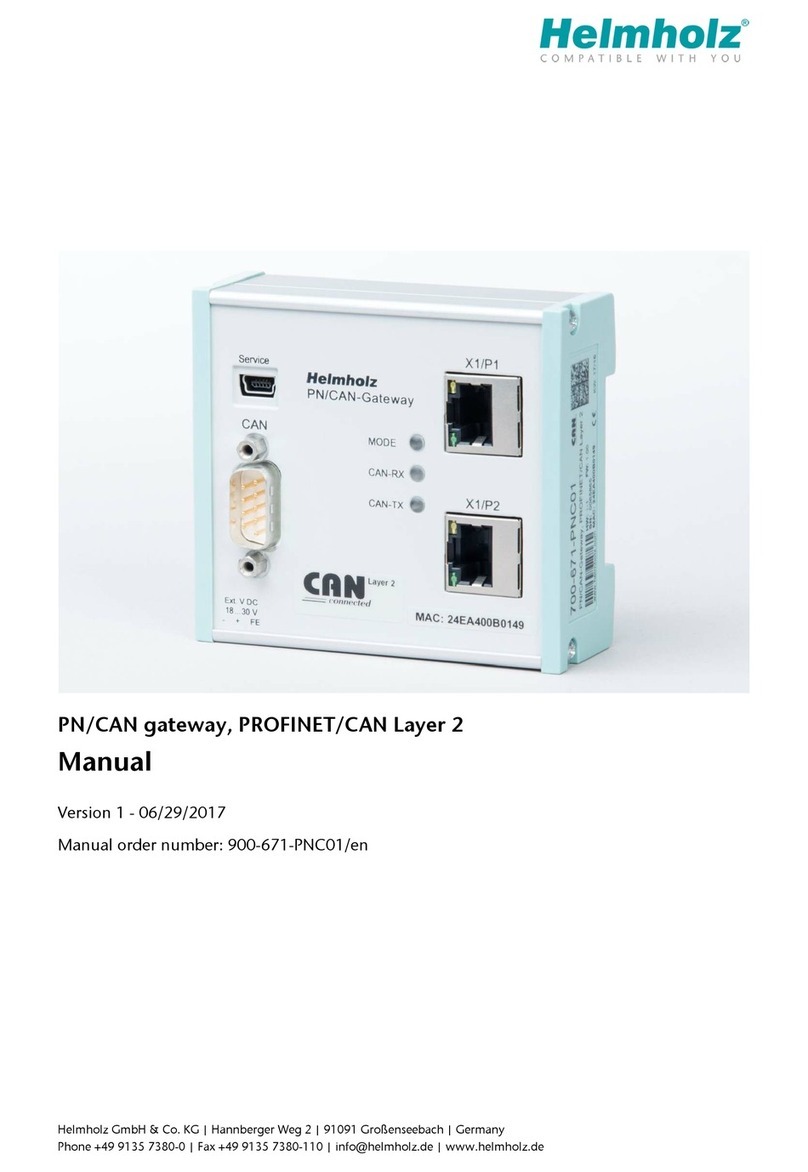
bihl+Wiedemann AS-i/Modbus Gateway User manual

AS-i/Modbus Gateways
User Manual


AS-i Modbus Gateway Table of Contents
Subject to reasonable modifications due to technical advances.Copyright Bihl+Wiedemann, Printed in Germany
Bihl+Wiedemann GmbH · D-68199 Mannheim · Tel. +49-621-339960 · Fax +49-621-3392239 · Internet http://www.bihl-wiedemann.de
issue date 11.1.2000
3
Table of Contents
1The Used Symbols ...................................................................................7
2Safety ........................................................................................................9
2.1 Intended Use ........................................................................................................... 9
2.2 General Safety Information .................................................................................... 9
3General Information ...............................................................................11
4Connections, Displays and Operating Keys ........................................13
4.1 Power Supply Concepts and AS-i Connection Techniques ............................. 13
4.1.1 Devices in IP65 ....................................................................................................... 13
4.1.2 Single Masters in IP20 with power supply A ........................................................... 14
4.1.3 Single Masters in IP20 with power supply N ...........................................................15
4.1.4 Double Master in IP20 with Power Supply A .......................................................... 18
4.1.5 Double Master in IP20 with Power Supply N .......................................................... 21
4.2 The Serial Interfaces ............................................................................................. 24
4.2.1 AS-i/Modbus Gateway with RS485 ........................................................................24
4.2.2 AS-i/Modbus Gateway with RS422 ........................................................................24
4.2.3 AS-i/Modbus Gateway with RS232C ..................................................................... 25
4.2.4 AS-i/Modbus Gateway in IP65 ................................................................................25
4.3 Display and Operating Elements ......................................................................... 26
4.3.1 LEDs of the Single Masters .................................................................................... 26
4.3.2 LEDs of the Double Masters ................................................................................... 27
5Advanced Diagnostics for AS-i Masters ..............................................29
5.1 List of Corrupted AS-i Slaves (LCS) ................................................................... 29
5.2 Error Counter: Counter of corrupted data telegrams ........................................ 29
5.3 Off-line Phase on Configuration Errors .............................................................. 29
6Operating the AS-i/Modbus Gateway ..................................................31
6.1 Peculiarities with Double Masters ....................................................................... 31
6.2 Master Start-Up ..................................................................................................... 31
6.3 Configuration Mode .............................................................................................. 32
6.4 Protected Operating Mode ................................................................................... 32
6.4.1 Switching to Protected Operating Mode ................................................................ 32
6.4.2 Configuration Errors in Protected Operating Mode ................................................. 33
6.5 Assigning an AS-i Address in Configuration Mode .......................................... 33
6.5.1 Assigning a Slave Address ..................................................................................... 33
6.5.2 Erasing the Slave Address .....................................................................................33
6.6 Programming the Address in Case of Configuration Errors ............................ 34
6.6.1 Automatic Address Assignment .............................................................................. 34
6.6.2 Manual Address Assignment .................................................................................. 34
6.7 Adjusting the Modbus-Address and Interface-Configuration ..........................35
6.8 Error Messages ..................................................................................................... 36

AS-i Modbus Gateway Table of Contents
Subject to reasonable modifications due to technical advances.Copyright Bihl+Wiedemann, Printed in Germany
Bihl+Wiedemann GmbH · D-68199 Mannheim · Tel. +49-621-339960 · Fax +49-621-3392239 · Internet http://www.bihl-wiedemann.de
issue date 11.1.2000
4
7Operation via Modbus ........................................................................... 37
7.1 Configuring the Interface .....................................................................................37
7.2 Message Structure ................................................................................................37
7.3 Modbus Functions ................................................................................................38
7.3.1 Function 1: “Read Coil Status” ................................................................................38
7.3.2 Function 2: “Read Input Status” ..............................................................................38
7.3.3 Function 3: “Read Holding Registers” .....................................................................38
7.3.4 Function 4: “Read Input Registers” .........................................................................39
7.3.5 Function 5: “Force Single Coil” ...............................................................................39
7.3.6 Function 6: “Preset Single Register” .......................................................................39
7.3.7 Function 15: “Force Multiple Coils” .........................................................................39
7.3.8 Function 16: “Preset Multiple Registers” .................................................................40
7.3.9 Function 17: “Report Slave ID” ...............................................................................40
7.3.10 Function 7: “Read Exception Status” ......................................................................40
7.3.11 Function 8: “Diagnostics” ........................................................................................41
7.3.12 Function 65: user defined function #1 .....................................................................42
7.3.13 Function 66: user defined function #2 .....................................................................43
7.3.14 Function 67: user defined function #3 .....................................................................44
8Address-Table of the Modbus Interfaces ............................................ 45
8.1 Discrete Outputs (“Coils”) ...................................................................................45
8.2 Discrete Inputs (“nputs”) .....................................................................................47
8.3 Read/Write-Registers (“Holding Registers”) ......................................................48
8.4 Read-Only-Registers (“Input Registers”) ...........................................................54
9Appendix: Displays of the Figure Display ........................................... 57
10 Appendix: The First Commissioning of AS-i ...................................... 59

AS-i/Modbus Gateway
Subject to reasonable modifications due to technical advances Copyright Bihl+Wiedemann, Printed in Germany
Bihl+WiedemannGmbH · D-68199Mannheim · Phone+49-621-339960 · Fax+49-621-3392239 · Internethttp://www.bihl-wiedemann.de
issue date11.1.2000
5
Declaration of Conformity
according to 89/336/EEC and 73/23/EEC
Bihl+Wiedemann GmbH, Mannheim, hereby declares under its sole responsibility
that the products mentioned below are according to the listed harmonized standards
or normative documents and (where neccessary) a component body has been re-
leased.
Specification: AS-i/Modbus Gateway
Article-no.: 1048, 1049, 1050, 1051, 1052, 1053,
1036, 1037, 1038, 1039, 1040, 1041,
1104,
1141, 1142, 1143, 1144, 1145, 1146,
1153, 1154, 1155, 1156, 1157, 1158
Applied harmonized Standards:
EN 50081-2
EN 61000-6-2
Applied national standards or normative documents:
AS-i Complete Specification (EN50295)
Prüfungsordnung für AS-i Master
Manufacturer: Bihl+Wiedemann GmbH
Date: 16.06.98 Bernhard Wiedemann

AS-i/Modbus Gateway Declaration of Conformity
Subject to reasonable modifications due to technical advances.Copyright Bihl+Wiedemann, Printed in Germany
Bihl+Wiedemann GmbH · D-68199 Mannheim · Tel. +49-621-339960 · Fax +49-621-3392239 · Internet http://www.bihl-wiedemann.de
issue date 11.1.2000
6

AS-i/Modbus Gateway The Used Symbols
Subject to reasonable modifications due to technical advances Copyright Bihl+Wiedemann, Printed in Germany
Bihl+Wiedemann GmbH · D-68199 Mannheim · Tel. +49-621-339960 · Fax +49-621-3392239 · Internet http://www.bihl-wiedemann.de
issue date 11.1.2000
7
1The Used Symbols
This symbol warns the user of possible danger. Failure to heed this
warning can lead to personal injury or death and/or damage to equip-
ment.
This symbol warns the user of a possible failure. Failure to heed this
warning can lead to total failure of the equipment or any other con-
nected equipment.
This symbol gives the user important hints.

AS-i/Modbus Gateway The Used Symbols
Subject to reasonable modifications due to technical advance.Copyright Bihl+Wiedemann, Printed in Germany
Bihl+Wiedemann GmbH · D-68199 Mannheim · Tel. +49-621-339960 · Fax +49-621-3392239 · Internet http://www.bihl-wiedemann.de
issue date 11.1.2000
8

AS-i/Modbus Gateway Safety
Subject to reasonable modifications due to technical advances Copyright Bihl+Wiedemann, Printed in Germany
Bihl+Wiedemann GmbH · D-68199 Mannheim · Tel. +49-621-339960 · Fax +49-621-3392239 · Internet http://www.bihl-wiedemann.de
issue date 11.1.2000
9
2Safety
2.1 Intended Use
2.2 General Safety Information
The protection of operating personnel and the system against possible
danger is not guaranteed if the control interface unit is not operated in
accordance with its intended use.
The device may only be operated by appropriately qualified personnel
in accordance with this operating manual.
Safety and correct functioning of the device cannot be guaranteed if any
operation other than that described in this operation manual is per-
formed.
The connecting of the equipment and any maintenance work to be car-
ried out with voltage applied to the equipment must only be performed
by appropriately qualified electrotechnical personnel.
In the case that a failure cannot be repaired, the device must be taken
out of operation and kept from inadvertently put back into operation.
Repair work is to be carried out by the manufacturer only. Additions or
modifications to the equipment are not allowed and void the warranty.
The operator is responsible for the observance of local safety stan-
dards.

AS-i/Modbus Gateway Safety
Subject to reasonable modifications due to technical advance.Copyright Bihl+Wiedemann, Printed in Germany
Bihl+Wiedemann GmbH · D-68199 Mannheim · Tel. +49-621-339960 · Fax +49-621-3392239 · Internet http://www.bihl-wiedemann.de
issue date 11.1.2000
10

AS-i/Modbus Gateway General Information
Subject to reasonable modifications due to technical advances Copyright Bihl+Wiedemann, Printed in Germany
Bihl+Wiedemann GmbH · D-68199 Mannheim · Tel. +49-621-339960 · Fax +49-621-3392239 · Internet http://www.bihl-wiedemann.de
issue date 11.1.2000
11
3General Information
This operating instruction is for use with the following devices of the Bihl+Wiedemann
GmbH:
AS-i gateway to Modbus with mini-PLC "AS-i control":
•AS-i/Modbus gateway with RS232C power supply A article-no. 1048
•AS-i/Modbus gateway with RS485 power supply A article-no. 1049
•AS-i/Modbus gateway with RS422 power supply A article-no. 1050
•AS-i/Modbus gateway with RS232C power supply N article-no. 1051
•AS-i/Modbus gateway with RS485 power supply N article-no. 1052
•AS-i/Modbus gateway with RS422 power supply N article-no. 1053
AS-i gateway to Modbus without mini-PLC "AS-i control":
•AS-i/Modbus gateway with RS232C power supply A article-no. 1036
•AS-i/Modbus gateway with RS485 power supply A article-no. 1037
•AS-i/Modbus gateway with RS422 power supply A article-no. 1038
•AS-i/Modbus gateway with RS232C power supply N article-no. 1039
•AS-i/Modbus gateway with RS485 power supply N article-no. 1040
•AS-i/Modbus gateway with RS422 power supply N article-no. 1041
AS-i gateway to Modbus (2 AS-imasters) with mini-PLC "AS-i control":
•AS-i/Modbus gateway with RS232C power supply A article-no. 1153
•AS-i/Modbus gateway with RS485 power supply A article-no. 1154
•AS-i/Modbus gateway with RS422 power supply A article-no. 1155
•AS-i/Modbus gateway with RS232C power supply N article-no. 1156
•AS-i/Modbus gateway with RS485 power supply N article-no. 1157
•AS-i/Modbus gateway with RS422 power supply N article-no. 1158
AS-i gateway to Modbus (2 AS-imasters) without mini-PLC "AS-i control":
•AS-i/Modbus gateway with RS232C power supply A article-no. 1141
•AS-i/Modbus gateway with RS485 power supply A article-no. 1142
•AS-i/Modbus gateway with RS422 power supply A article-no. 1143
•AS-i/Modbus gateway with RS232C power supply N article-no. 1144
•AS-i/Modbus gateway with RS485 power supply N article-no. 1145
•AS-i/Modbus gateway with RS422 power supply N article-no. 1146
AS-i gateway to Modbus in protection class IP65:
•AS-i/Modbus gateway with RS232C power supply A article-no. 1104
The AS-i/Modbus gateways serve to connect AS-Interface systems to the Modbus.
The devices can be delivered in a housing for cabinet mounting or in a field housing
in IP65. The gateways for cabinet mounting can be chosen to link one or two
AS-InterfacenetworkstoModbus with upto57600Baud. The AS-i/Modbus gateways
for 2 AS-i networks with Master power supply N offer the possibility to operate two
AS-i networks with only one gateway and only one AS-Interface power supply.

AS-i/Modbus Gateway General Information
Subject to reasonable modifications due to technical advance.Copyright Bihl+Wiedemann, Printed in Germany
Bihl+Wiedemann GmbH · D-68199 Mannheim · Tel. +49-621-339960 · Fax +49-621-3392239 · Internet http://www.bihl-wiedemann.de
issue date 11.1.2000
12
All AS-i functions can be called via Modbus. The AS-i data can be controlled binarily
(functions 1, 2, 5 and 15) and by using registers (functions 3, 4, 6 and 16). Modbus
diagnostic registers are supported.
The AS-Interface data can be used in many different ways. All the important data are
available in three different forms - binarily, packed or unpacked in registers. The AS-i
masters with the Modbus slave-interface can thus be operated without expensive
adaptions. Furthermore advanced AS-i diagnostics are implemented to identify occa-
sional occuring configuration errors and to judge the quality of the AS-i communica-
tion.
The mini-PLC (AS-i Control II) is capable to preprocess the actuator-sensor-data with-
in the gateway. All AS-i Control functions are usable (program download, upload,
start, stop; read and write flags). There are AS-i/Modbus gateways without mini-PLC
on offer as well. The gateways for cabinet mounting can be delivered with RS232,
RS485 or RS422 to interface the Modbus.
The handling of the AS-i/Modbus gateway in IP65 is identically with the AS-i/Modbus
gateway in IP20. The high protection category IP 65 makes the device suitable for ap-
plications in the extremee industrial environments frequently encountered in the field.
AS-Interface is connected using the penetration technique of EMS (electromechani-
cal Interface) Modbus is connected with heavy gauge terminals and cage clamp ter-
minal blocks.
With all types of AS-i/Modbus gateways commissioning, debugging and setting up of
the AS-i parameters can be accomplished with the use of two push-buttons, the dis-
play and the LEDs directly on the system. The AS-i control Tools are included in the
package, making it possible to commission and to program the device from a serial
interface of thePC without the need for additional expensive hardware.

AS-i/Modbus Gateway Connections, Displays and Operating Keys
Subject to reasonable modifications due to technical advances Copyright Bihl+Wiedemann, Printed in Germany
Bihl+Wiedemann GmbH · D-68199 Mannheim · Tel. +49-621-339960 · Fax +49-621-3392239 · Internet http://www.bihl-wiedemann.de
issue date 11.1.2000
13
4Connections, Displays and Operating Keys
Devices in IP20:
On the front panel of the AS-i/Modbus gateways are:
•terminals to connect the power supply and the AS-i circuit
•a 9-pin SUB-D connector as Modbus interface
•7 LEDs
•a two-digit seven-segment display
•2 push-buttons to configure the gateway
Devices in IP65:
The devices in IP65 have the terminals for Modbus (cage clamp terminals) and the
push buttons under the top of the housing to prevent liquids from entering. The
AS-interface is connected with the electromechanical interface with penetration tech-
nique developed for AS-i at the bottom of the housing.
4.1 Power Supply Concepts and AS-i Connection Techniques
4.1.1 Devices in IP65
Every AS-i master and all the AS-i gateways in IP65 come with power supply A. An
AS-i power supply has to be used which also supplies the AS-i master with power and
can be connected to the AS-i cable like all the other AS-i components at any place.
The AS-i masters as well as all the AS-i gateways of the are available
with two different power supply concepts, "master power supply A" and
"master power supply N".

AS-i/Modbus Gateway Connections, Displays and Operating Keys
Subject to reasonable modifications due to technical advance.Copyright Bihl+Wiedemann, Printed in Germany
Bihl+Wiedemann GmbH · D-68199 Mannheim · Tel. +49-621-339960 · Fax +49-621-3392239 · Internet http://www.bihl-wiedemann.de
issue date 11.1.2000
14
The AS-i master is connected to AS-i using the penetration technique of the electro-
mechanical interface which is common with AS-i slaves as well.
4.1.2 Single Masters in IP20 with power supply A
The terminals have the following functions:
•+"AS-i +", Actuator Sensor Interface, positive terminal
•-"AS-i -", Actuator Sensor Interface, negative terminal
•GND,Groundterminal,used forbetter EMC.Should beconnected witha shortwire
to machine GND.
The AS-i masters with master power supply A do not need a voltage
supply of their own. They can be powered completely out of the AS-i
line (the power consumption is about 200 mA from AS-i). An additional
24 V voltage source is not necessary. The AS-i master merely requires
the connection to the AS-i line. When the AS-i power supply is switched
on, the master starts to operate.
AS-i Master
AS-i
power
AS-i
Slave AS-i
Slave AS-i
Slave
AS-i power
supply
AS-i master
AS-i power
GND+-+-

AS-i/Modbus Gateway Connections, Displays and Operating Keys
Subject to reasonable modifications due to technical advances Copyright Bihl+Wiedemann, Printed in Germany
Bihl+Wiedemann GmbH · D-68199 Mannheim · Tel. +49-621-339960 · Fax +49-621-3392239 · Internet http://www.bihl-wiedemann.de
issue date 11.1.2000
15
4.1.3 Single Masters in IP20 with power supply N
At the bottom of the unit there are 10 terminals for the power supply and the AS-i net-
work. The jumper settings (J+, J-) decide whether AS-i is powered by a separate AS-i
power supply or by the power supply that also provides the AS-i master.
The terminals have the following functions:
+"AS-i +", Actuator Sensor Interface, positive terminal
This terminal is connected internally with the center contact of jumper "J+".
-"AS-i -", Actuator Sensor Interface, negative terminal
This terminal is connected internally with the center contact of jumper "J-".
24V Master power supply, positive terminal (18 - 31.6 V DC)
0V Master power supply, negative terminal
GND Ground terminal, used for better EMC.
Should be connected with a short wire to machine GND.
Connection samples for the AS-i power supply:
In the wiring schemes above the current through the AS-i master
must not exceed 5 A.
AS-i Master
max. 10 A
PELV according to EN 60950
(Protective extra low voltage)
AS-i
power
supply
-
+
AS-i Slave
-
+
AS-i Slave
-
+
AS-i Master
max. 5 A
PELV according to EN
60950 (Protective extra
low voltage)
AS-i
power
supply
-
+
AS-i Slave
-
+
AS-i Slave
-
+
AS-i Master
AS-i power
GND24V 0V+-J+ J-

AS-i/Modbus Gateway Connections, Displays and Operating Keys
Subject to reasonable modifications due to technical advance.Copyright Bihl+Wiedemann, Printed in Germany
Bihl+Wiedemann GmbH · D-68199 Mannheim · Tel. +49-621-339960 · Fax +49-621-3392239 · Internet http://www.bihl-wiedemann.de
issue date 11.1.2000
16
J+, J- Jumpers for selecting the power supply of AS-i
"int pwr" position (closed):
AS-i is powered by the master power supply.
Master power supply and AS-i network are then decoupled with coils.
"ext pwr" position (open):
With the jumper open (or missing), the AS-i network must be powered by
a separate AS-i power supply.
TheAS-i power supplycan be connected to the jumper or totheAS-i cable
in the field.
Operation without AS-i power supply
When the jumpers are in position "int pwr", the AS-i network is powered by the mas-
ter's power supply. For test purposes, it is possible to use a conventional 24 V DC
power supply to supply the AS-i network. You get optimum results with a 30 V DC volt-
age source.
For the following wiring scheme the current through the AS-i mas-
ter must not exceed 2.8 A.
AS-i Master
-
+
Master
power
supply
max. 2.8 A
29.5 - 31.6 V DC
PELV according to EN 60950
(Protective extra low voltage)
AS-i Slave
-
+

AS-i/Modbus Gateway Connections, Displays and Operating Keys
Subject to reasonable modifications due to technical advances Copyright Bihl+Wiedemann, Printed in Germany
Bihl+Wiedemann GmbH · D-68199 Mannheim · Tel. +49-621-339960 · Fax +49-621-3392239 · Internet http://www.bihl-wiedemann.de
issue date 11.1.2000
17
This connection technique serves also for providing more than one AS-i master out of
one master power supply because each AS-i circuit is decoupled with its own in the
AS-i master integrated coils.
Operation with AS-i power supply
In the jumper position "ext pwr" the AS-i network needs an additional AS-i power sup-
ply.
AS-i Master N
-
+
Master
power
supply
max. N x 2.8 A
29.5 - 31.6 V DC
PELV according to
EN 60950
(Protective extra low
voltage)
Fuse
2.8 A T
Fuse
2.8 A T Fuse
2.8 A T
...
AS-i Slave
-
+
AS-i Master 2
AS-i Slave
-
+
AS-i Master 1
AS-i Slave
-
+
AS-i Master
18 - 31.6 V
150 mA
PELV according to EN 60950
(Protective extra low voltage)
max. 10 A
PELV according to EN 60950
(Protective extra low voltage)
AS-i
powers
upply
-
+
AS-i Slave
-
+
-
+
master
powers
upply

AS-i/Modbus Gateway Connections, Displays and Operating Keys
Subject to reasonable modifications due to technical advance.Copyright Bihl+Wiedemann, Printed in Germany
Bihl+Wiedemann GmbH · D-68199 Mannheim · Tel. +49-621-339960 · Fax +49-621-3392239 · Internet http://www.bihl-wiedemann.de
issue date 11.1.2000
18
Do not try to provide the AS-i master with power supply N out of the AS-i power supply
of the AS-i circuit („backwards“), because the additional decoupling coils would bur-
den the AS-i line and cause erroneous AS-i telegrams.
4.1.4 Double Master in IP20 with Power Supply A
The terminals have the following functions:
+"AS-i +", Actuator Sensor Interface 1 or 2, positive terminal
These terminals are connected internally with point a2 of jumper "J+".
-"AS-i -", Actuator Sensor Interface 1 or 2, negative terminal
These terminals are connected internally with point b2 of jumper "J-".
24V Master power supply, positive terminal (18 - 31.6 V DC)
0V Master power supply, negative terminal
GND Ground terminal, used for better EMC.
Should be connected with a short wire to machine GND.
J+, J- Jumpers for selecting the power supply of AS-i
jumpers closed:
The AS-i master is powered out of AS-i circuit 1.
Master power supply and AS-i network are then decoupled with coils.
AS-i Master
AS-i
powers
upply
-
+
AS-i Slave
-
+
AS-i Master
AS-i 1 power
GNDa224V 0V
+-
J+ J-
b2
+-+-+-
AS-i 2

AS-i/Modbus Gateway Connections, Displays and Operating Keys
Subject to reasonable modifications due to technical advances Copyright Bihl+Wiedemann, Printed in Germany
Bihl+Wiedemann GmbH · D-68199 Mannheim · Tel. +49-621-339960 · Fax +49-621-3392239 · Internet http://www.bihl-wiedemann.de
issue date 11.1.2000
19
jumpers open:
With the jumpers open (or missing), the AS-i master must be powered
by a separate 24 V DC power supply.
Power supply out of AS i circuit 1
AS-i Master
AS-i 1 power
GND
a2
24V
0V
J+
J-
b2
+
-
+
-
AS-i 2
max. 10 A
PELV according to EN 60950
(Protective extra low voltage)
-
+
AS-i Slave
-
+
max. 10 A
PELV according to EN 60950
(Protective extra low voltage)
100m AS-i cable
31 AS-i Slaves
100m AS-i cable
31 AS-i Slaves
AS-i
power
supply
AS-i
power
supply
-
+
AS-i Slave
-
+
+
-
+
-

AS-i/Modbus Gateway Connections, Displays and Operating Keys
Subject to reasonable modifications due to technical advance.Copyright Bihl+Wiedemann, Printed in Germany
Bihl+Wiedemann GmbH · D-68199 Mannheim · Tel. +49-621-339960 · Fax +49-621-3392239 · Internet http://www.bihl-wiedemann.de
issue date 11.1.2000
20
Operation with separate 24 V DC power supply
Connection variations for the AS-i circuits (here only displayed for one AS-i circuit)
In the wiring schemes above the current through the AS-i master
must not exceed 5 A.
AS-i Master
AS-i 1 power
GND
a2
b2
+
-
+
-
AS-i 2
max. 10 A
PELV according to EN 60950
(Protective extra low voltage)
-
+
AS-i Slave
-
+
max. 10 A
PELV according to EN 60950
(Protective extra low voltage)
-
+
AS-i Slave
-
+
-
+
18 - 31.6 V DC
150 mA
PELV according to EN 60950
(Protective extra low voltage)
-
+
-
+
0V
24V
100m AS-i cable
31 AS-i Slaves
100m AS-i cable
31 AS-i Slaves
AS-i
power
supply
AS-i
power
supply
AS-i
power
supply
AS-i Master
max. 10 A
PELV according to EN 60950
(Protective extra low voltage)
AS-i
power
supply
-
+
AS-i Slave
-
+
AS-i Slave
-
+
max. 5 A
PELV according to EN 60950
(Protective extra low voltage)
AS-i
power
supply
-
+
AS-i Slave
-
+
AS-i Slave
-
+
AS-i Master
Table of contents
Other bihl+Wiedemann Gateway manuals
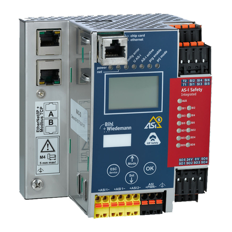
bihl+Wiedemann
bihl+Wiedemann BWU3857 User manual
bihl+Wiedemann
bihl+Wiedemann BWU3593 User manual

bihl+Wiedemann
bihl+Wiedemann AS-i 2.1 User manual
bihl+Wiedemann
bihl+Wiedemann 1062 User manual
bihl+Wiedemann
bihl+Wiedemann BWU3543 User manual
bihl+Wiedemann
bihl+Wiedemann 1435 User manual
bihl+Wiedemann
bihl+Wiedemann 1249 User manual
bihl+Wiedemann
bihl+Wiedemann 1116 User manual

bihl+Wiedemann
bihl+Wiedemann BWU3683 User manual
