bihl+Wiedemann AS-i 2.1 User manual

AS-i 2.1
AS-i/CANopen Gateway
User Manual


AS-i/CANopen Gateway Table of Contents
Subject to reasonable modifications due to technical advances Copyright Bihl+Wiedemann, Printed in Germany
Bihl+Wiedemann GmbH · D-68199 Mannheim · Phone +49-621-339960 · Fax +49-621-3392239 · Internet http://www.bihl-wiedemann.de
issue date 27.1.2003
1
Table of Contents
1 The Symbols Used .............................................................................. 7
2 Safety .................................................................................................... 9
2.1 Intended Use ...................................................................................................... 9
2.2 General Safety Information ............................................................................... 9
3 General Information ..........................................................................11
4 Description ......................................................................................... 15
4.1 LED Displays .................................................................................................... 15
4.2 Power Supply Concepts and AS-i Connection Techniques ........................ 15
4.2.1 Single Masters with Power Supply A ................................................................. 15
4.2.2 Double Master in IP20 with AS-i Power Supply A ............................................. 16
4.3 The fieldbus interface ..................................................................................... 19
4.4 Display and Operating Elements ................................................................... 19
4.4.1 LEDs of the Single Masters and Double Masters .............................................. 19
4.4.2 Push-Buttons ..................................................................................................... 19
5 Operating the AS-i/CANopen Gateway ............................................ 21
5.1 Peculiarities with Double Masters ................................................................. 21
5.2 Master Start-Up ................................................................................................ 21
5.3 Configuration Mode ......................................................................................... 22
5.4 Protected Operating Mode .............................................................................. 22
5.4.1 Switching to Protected Operating Mode ............................................................ 22
5.4.2 Configuration Errors in Protected Operating Mode ........................................... 23
5.5 Assigning an AS-i Address in Configuration Mode ..................................... 23
5.5.1 Assigning a Slave Address ................................................................................ 23
5.5.2 Erasing the Slave Address ................................................................................ 23
5.6 Programming the Address in Case of Configuration Errors ....................... 24
5.6.1 Automatic Address Assignment ......................................................................... 24
5.6.2 Manual Address Assignment ............................................................................. 24
5.7 Adjusting the CANopen Node Address and Baud Rate ............................... 25
5.7.1 CANopen Node Address ................................................................................... 25
5.7.2 Baud Rate .......................................................................................................... 25
5.8 Error Messages ................................................................................................ 26
6 Operating by Full-graphic Display ................................................... 27
6.1 CANopen (Fieldbus Interface) ........................................................................ 29
6.1.1 CANopen Node Address ................................................................................... 29
6.1.2 CANopen Baud Rate ......................................................................................... 30
6.1.3 CANopen Status ................................................................................................ 30
6.2 Setup (Configuration of the AS-i Circuit) ...................................................... 31
6.2.1 AS-i Circuit ......................................................................................................... 31
6.2.2 AS-i Slave Addr (AS-i Slave Address) ............................................................... 31
6.2.3 Force Offline (switch AS-i Master offline) .......................................................... 32

AS-i/CANopen Gateway Table of Contents
Subject to reasonable modifications due to technical advances Copyright Bihl+Wiedemann, Printed in Germany
Bihl+Wiedemann GmbH · D-68199 Mannheim · Phone +49-621-339960 · Fax +49-621-3392239 · Internet http://www.bihl-wiedemann.de
issue date 27.1.2003
2
6.2.4 Operation Mode ................................................................................................. 32
6.2.5 Store Act Cfg (Store Actual Detected Configuration) ......................................... 33
6.2.6 Permanent Param (Projected Parameter) .........................................................33
6.2.7 Permanent Cfg (Projected Configuration Data) ................................................. 33
6.2.8 Addr. Assistant (Address Assistent) ................................................................... 34
6.2.9 LOS (List of Offline-Slaves) ............................................................................... 34
6.3 IO + Param. Test (Testing AS-i In- and Outputs as well as
AS-i Parameters) .............................................................................................. 35
6.3.1 Binary Inputs ...................................................................................................... 35
6.3.2 Binary Outputs ...................................................................................................35
6.3.3 Analog Inputs ..................................................................................................... 36
6.3.4 Analog Outputs .................................................................................................. 36
6.3.5 Parameter .......................................................................................................... 36
6.4 Diagnosis (Normal AS-i Diagnosis) ................................................................ 37
6.4.1 EC-Flags (Execution Control Flags) .................................................................. 37
6.4.2 Actual Config (Actual Configuration) .................................................................. 38
6.4.3 LPF (List of Periphery Faults) ............................................................................38
6.4.4 AS-i Master (Info) ...............................................................................................39
6.5 Adv. Diagnosis (Advanced AS-i Diagnosis) .................................................. 39
6.5.1 Error Counters ................................................................................................... 39
6.5.2 LCS (List of Slaves, that produced a Configuration Error) ................................. 39
6.6 AS-i Safety ........................................................................................................ 40
6.6.1 Safety Slaves ..................................................................................................... 40
6.6.2 Safety Monitor .................................................................................................... 41
7 Advanced Diagnostics for AS-i Masters ......................................... 43
7.1 List of Corrupted AS-i Slaves (LCS) ............................................................... 43
7.2 Protocol Analysis: Counters of Corrupted Data Telegrams ........................ 43
7.3 Off-line Phase on Configuration Errors (LOS) .............................................. 43
8 Operation as CANopen Node ........................................................... 45
8.1 CANopen Parameter Communication ............................................................ 46
8.1.1 Object Directory ................................................................................................. 46
8.2 Process Data Communication ........................................................................48
8.2.1 Mapping AS-i Data in CANopen PDOs ..............................................................48
8.2.1.1 Receive-PDOs ...................................................................................................50
8.2.1.2 Send-PDOs ........................................................................................................ 50
9 CANopen Telegrams ......................................................................... 51
9.1 Representation of a CAN Message ................................................................ 51
9.2 Default Identifier Distribution ......................................................................... 52
9.2.1 Simplified Boot-up According to CANopen (NMT=0, DBT=0) ............................ 53
9.2.2 Examples for data exchange ............................................................................. 55
10 CANopen ............................................................................................ 57
10.1 Mailbox .............................................................................................................. 57
10.1.1 Construction .......................................................................................................57
10.1.1.1 Values for command .......................................................................................... 58
10.1.1.2 Values for results ...............................................................................................60

AS-i/CANopen Gateway Table of Contents
Subject to reasonable modifications due to technical advances Copyright Bihl+Wiedemann, Printed in Germany
Bihl+Wiedemann GmbH · D-68199 Mannheim · Phone +49-621-339960 · Fax +49-621-3392239 · Internet http://www.bihl-wiedemann.de
issue date 27.1.2003
3
10.1.2 Mailbox commands ............................................................................................ 60
10.1.2.1 IDLE ...................................................................................................................60
10.1.2.2 READ_IDI .......................................................................................................... 60
10.1.2.3 WRITE_ODI ....................................................................................................... 61
10.1.2.4 Set_Permanent_Parameter (SET_PP) .............................................................. 62
10.1.2.5 Get_Permanent_Parameter (GET_PP) ............................................................. 62
10.1.2.6 Write Parameter (WRITE_P) ............................................................................. 62
10.1.2.7 Read Parameter (READ_PI) ............................................................................. 63
10.1.2.8 Store Actual Parameters (STORE_PI) .............................................................. 64
10.1.2.9 Set Permanent Configuration (SET_PCD) ........................................................ 64
10.1.2.10 Get Extended Permanent Configuration (GET_PCD) ....................................... 65
10.1.2.11 Store Actual Configuration (STORE_CDI) ......................................................... 65
10.1.2.12 Read Actual Configuration (READ_CDI) ........................................................... 66
10.1.2.13 SET_LPS ........................................................................................................... 66
10.1.2.14 GET_LPS .......................................................................................................... 67
10.1.2.15 GET_LAS .......................................................................................................... 68
10.1.2.16 GET_LDS .......................................................................................................... 69
10.1.2.17 GET_FLAGS ..................................................................................................... 69
10.1.2.18 SET_OP_MODE ................................................................................................ 70
10.1.2.19 SET_OFFLINE .................................................................................................. 71
10.1.2.20 SET_DATA_EX ................................................................................................. 72
10.1.2.21 Change Slave Address (SLAVE_ADDR) ........................................................... 72
10.1.2.22 Set Auto Address Enable (SET_AAE) ............................................................... 73
10.1.2.23 GET_LPF ........................................................................................................... 74
10.1.2.24 Write AS-i Slave Extended ID1 (WRITE_XID1) ................................................. 74
10.1.2.25 RD_7X_IN ......................................................................................................... 75
10.1.2.26 WR_7X_OUT ..................................................................................................... 75
10.1.2.27 RD_7X_OUT ..................................................................................................... 76
10.1.2.28 RD_7X_IN_X ..................................................................................................... 76
10.1.2.29 WR_7X_OUT_X ................................................................................................ 77
10.1.2.30 RD_7X_OUT_X ................................................................................................. 77
10.1.2.31 READ_ODI ........................................................................................................ 78
10.1.2.32 GET_DELTA ...................................................................................................... 78
10.1.2.33 WR_74_PARAM ................................................................................................ 79
10.1.2.34 RD_74_PARAM ................................................................................................. 79
10.1.2.35 RD_74_ID .......................................................................................................... 80
10.1.2.36 RD_74_DIAG ..................................................................................................... 80
10.1.2.37 Get_LPS, Get_LAS, Get_LDS, Get_Flags (GET_LISTS) ................................. 81
10.1.2.38 GET_LCS .......................................................................................................... 83
10.1.2.39 GET_LOS .......................................................................................................... 83
10.1.2.40 SET_LOS .......................................................................................................... 84
10.1.2.41 GET_TECA ........................................................................................................ 85
10.1.2.42 GET_TECB ........................................................................................................ 85
10.1.2.43 GET_TEC_X ...................................................................................................... 86
10.1.2.44 BUTTONS ......................................................................................................... 86
10.1.2.45 INVERTER ........................................................................................................ 87
10.1.2.46 FP_PARAM ....................................................................................................... 87
10.1.2.47 FP_DATA .......................................................................................................... 88
10.1.3 Functional profiles ............................................................................................. 88

AS-i/CANopen Gateway Table of Contents
Subject to reasonable modifications due to technical advances Copyright Bihl+Wiedemann, Printed in Germany
Bihl+Wiedemann GmbH · D-68199 Mannheim · Phone +49-621-339960 · Fax +49-621-3392239 · Internet http://www.bihl-wiedemann.de
issue date 27.1.2003
4
10.1.3.1 „Safety at Work“ List 1 ....................................................................................... 88
10.1.3.2 „Safety at Work“ Monitor Diagnosis ................................................................... 90
10.1.3.3 Integrated AS-i Sensors: Warnings .................................................................... 91
10.1.3.4 Integrated AS-i Sensors: Availability .................................................................. 92
10.1.4 Mailbox example ................................................................................................ 93
11 Appendix: Displaying the Figure Display ....................................... 95
12 Appendix: The First Commissioning of AS-i .................................. 97
13 We Are Interested in Your Opinion! ................................................. 99

AS-i/CANopen Gateway
Subject to reasonable modifications due to technical advances Copyright Bihl+Wiedemann, Printed in Germany
Bihl+Wiedemann GmbH · D-68199 Mannheim · Phone +49-621-339960 · Fax +49-621-3392239 · Internet http://www.bihl-wiedemann.de
issue date 27.1.2003
5
Declaration of Conformity
according to 89/336/EEC and 73/23/EEC
Bihl+Wiedemann GmbH, Mannheim, hereby declares under its sole responsibility
that the products mentioned below are according to the listed harmonized stan-
dards or normative documents and (where neccessary) a component body has
been released.
Specification: AS-i/CANopen Gateway, AS-i Specification 2.1
Article-no.: BW1448, BW1449
Applied harmonized Standards:
EN 50081-2
EN 61000-6-2
Applied national standards or normative documents:
AS-i Complete Specification (EN50295)
Prüfungsordnung für AS-i Master
Manufacturer: Bihl+Wiedemann GmbH
Date: 01.08.02 Bernhard Wiedemann

AS-i/CANopen Gateway
Subject to reasonable modifications due to technical advances Copyright Bihl+Wiedemann, Printed in Germany
Bihl+Wiedemann GmbH · D-68199 Mannheim · Phone +49-621-339960 · Fax +49-621-3392239 · Internet http://www.bihl-wiedemann.de
issue date 27.1.2003
6

AS-i/CANopen Gateway The Symbols Used
Subject to reasonable modifications due to technical advances Copyright Bihl+Wiedemann, Printed in Germany
Bihl+Wiedemann GmbH · D-68199 Mannheim · Phone +49-621-339960 · Fax +49-621-3392239 · Internet http://www.bihl-wiedemann.de
issue date 27.1.2003
7
1 The Symbols Used
This symbol warns the user of possible danger. Failure to heed this
warning can lead to personal injury or death and/or damage to
equipment.
This symbol warns the user of a possible failure. Failure to heed this
warning can lead to total failure of the equipment or any other con-
nected equipment.
This symbol gives the user important hints.

AS-i/CANopen Gateway The Symbols Used
Subject to reasonable modifications due to technical advances Copyright Bihl+Wiedemann, Printed in Germany
Bihl+Wiedemann GmbH · D-68199 Mannheim · Phone +49-621-339960 · Fax +49-621-3392239 · Internet http://www.bihl-wiedemann.de
issue date 27.1.2003
8

AS-i/CANopen Gateway Safety
Subject to reasonable modifications due to technical advances Copyright Bihl+Wiedemann, Printed in Germany
Bihl+Wiedemann GmbH · D-68199 Mannheim · Phone +49-621-339960 · Fax +49-621-3392239 · Internet http://www.bihl-wiedemann.de
issue date 27.1.2003
9
2 Safety
2.1 Intended Use
2.2 General Safety Information
The protection of operating personnel and the system against possi-
ble danger is not guaranteed if the control interface unit is not oper-
ated in accordance with its intended use.
The device may only be operated by appropriately qualified person-
nel in accordance with this operating manual.
Safety and correct functioning of the device cannot be guaranteed if
any operation other than that described in this operation manual is
performed.
The connecting of the equipment and any maintenance work to be
carried out with voltage applied to the equipment must only be per-
formed by appropriately qualified electrotechnical personnel.
In the case that a failure cannot be repaired, the device must be
taken out of operation and kept from inadvertently put back into
operation.
Repair work is to be carried out by the manufacturer only. Additions
or modifications to the equipment are not allowed and void the war-
ranty.
The operator is responsible for the observance of local safety stan-
dards.

AS-i/CANopen Gateway Safety
Subject to reasonable modifications due to technical advances Copyright Bihl+Wiedemann, Printed in Germany
Bihl+Wiedemann GmbH · D-68199 Mannheim · Phone +49-621-339960 · Fax +49-621-3392239 · Internet http://www.bihl-wiedemann.de
issue date 27.1.2003
10

AS-i/CANopen Gateway General Information
Subject to reasonable modifications due to technical advances Copyright Bihl+Wiedemann, Printed in Germany
Bihl+Wiedemann GmbH · D-68199 Mannheim · Phone +49-621-339960 · Fax +49-621-3392239 · Internet http://www.bihl-wiedemann.de
issue date 27.1.2003
11
3 General Information
This operating instruction is for use with the following devices of the :
• AS-i/CANopen Gateway power supply A article-no. BW1448
• AS-i/CANopen Gateway power supply N article-no. BW1449
The AS-i/CANopen-Gateway serves to connect the AS-Interface to a superordina-
te CANopen. The Gateway acts as a complete Master for the AS-Interface and as
a slave for the CANopen.
New AS-i Specification 2.1
The AS-i/CANopen-Gateways already fulfil the new AS-i Specification 2.1. This
means:
• Up to 62 AS-Interface slaves can be connected per 1 AS-i network
• The transfer of analog signals via AS-i is integrated in the Masters
• All further functions of the new specification as e. g. the diagnosis of the AS-i
peripheral fault are implemented.
AS-i Scope Function
Diagnostics, which go far beyond the standard diagnostics facilitate the simple de-
tection of the occassionally occuring configuration errors and further irritations to-
wards the AS-i communication. So in case of an error the down time of machines
can be minimized or you can initiate preventive maintenance.
Commissioning and Monitoring
The AS-i/CANopen Gateways can be commissioned with the help of the software
"AS-i Control Tools" in combination with the CANopen Master Simulator. The EDS
file is included in the package.
Commissioning, debugging and setting up of the AS-i parameters without the soft-
ware can only be accomplished with the use of two push-buttons, the display and
the LEDs directly on the system.
Gateways with Graphical Display
The AS-i Gateways with Graphical Display are a high-end solution to link AS-In-
terfaces with a superior CANopen system.
Simple and Fast Commissioning
Using the AS-i Gateway with Graphical Display, the entire AS-i network can be
commissioned and the connected periphery can be completely tested without CA-
Nopen Master. The new interactive graphic display also enables the user to com-
plete all tasks which previously required the "AS-i Control Tools" software
package. This allows for simpler and faster commissioning.
Addressing Unit within the AS-i Master
With the help of the new graphical display, the hand held unit is now obsolete. The
slaves can now be easily addressed directly on the gateway. Slaves with extended
address mode are detected automatically and are used only when allowed. This

AS-i/CANopen Gateway General Information
Subject to reasonable modifications due to technical advances Copyright Bihl+Wiedemann, Printed in Germany
Bihl+Wiedemann GmbH · D-68199 Mannheim · Phone +49-621-339960 · Fax +49-621-3392239 · Internet http://www.bihl-wiedemann.de
issue date 27.1.2003
12
ensures that no two AS-i slaves with the same address will be on the same net-
work.
Testing of Connected Periphery without Additional Test Tools
Once the AS-Interface is put into operation, the cabling and the connected sensors
and actuators can be tested, inputs can be read and outputs can be set and even
analog sensors and actuators can be checked just using the Gateway with Graphi-
cal Display.
On-board Diagnostics:
Configuration Fault, Periphery Fault
At a glance, the display shows the configuration faults (missing slave, additional
slave detected, wrong slave type) as well as periphery faults, such as a short cir-
cuit at a sensor cable. This allows the user to get the proper information to solve
the problem in the shortest amount of time.
Detection of Occasional Faults
A list of slaves, which have previously caused an error, is also available through
the graphical display. This can be very helpful in solving problems.
Scope Functions shown on the Display
While strange phenomena can occur as the AS-Interface gets to its limits (e. g. ca-
ble length >100 m, EMC problems), the AS-i Gateway with Graphical Display has
on-board diagnostic tools. With the help of the AS-i error counters the user can ea-

AS-i/CANopen Gateway General Information
Subject to reasonable modifications due to technical advances Copyright Bihl+Wiedemann, Printed in Germany
Bihl+Wiedemann GmbH · D-68199 Mannheim · Phone +49-621-339960 · Fax +49-621-3392239 · Internet http://www.bihl-wiedemann.de
issue date 27.1.2003
13
sily check the quality of AS-i communications. The user can then test the impact
of any actions taken.
Accessories:
CANopen Master Simulator (Article no. BW1186)
Transmission cords for AS-i/CAN Gateways (Article no. BW1226)
Software AS-i Control Tools (Article no. BW1203)

AS-i/CANopen Gateway General Information
Subject to reasonable modifications due to technical advances Copyright Bihl+Wiedemann, Printed in Germany
Bihl+Wiedemann GmbH · D-68199 Mannheim · Phone +49-621-339960 · Fax +49-621-3392239 · Internet http://www.bihl-wiedemann.de
issue date 27.1.2003
14

AS-i/CANopen Gateway Description
Subject to reasonable modifications due to technical advances Copyright Bihl+Wiedemann, Printed in Germany
Bihl+Wiedemann GmbH · D-68199 Mannheim · Phone +49-621-339960 · Fax +49-621-3392239 · Internet http://www.bihl-wiedemann.de
issue date 27.1.2003
15
4 Description
4.1 LED Displays
4.2 Power Supply Concepts and AS-i Connection Techniques
4.2.1 Single Masters with Power Supply A
The terminals have the following functions:
+ "AS-i +", Actuator Sensor Interface, positive terminal
- "AS-i -", Actuator Sensor Interface, negative terminal
GND Ground terminal, used for better EMC.
Should be connected with a short wire to machine GND.
Display Color Description
power green Supply of the gateway
MNS green/red Module/Network state
config err red Configuration error
U ASI green The AS-i circuit is sufficiently powered
ASI aktiv green Normal operation active
prg enable green Automatic address programming enabled
prj mode yellow
The AS-i masters with master power supply A do not need a voltage
supply of their own. They can be powered completely out of the AS-i
line (the power consumption is about 200 mA from AS-i). An addi-
tional 24 V voltage source is not necessary. The AS-i master merely
requires the connection to the AS-i line. When the AS-i power supply
is switched on, the master starts to operate.
AS-i master
AS-i power
GND
+-+-

AS-i/CANopen Gateway Description
Subject to reasonable modifications due to technical advances Copyright Bihl+Wiedemann, Printed in Germany
Bihl+Wiedemann GmbH · D-68199 Mannheim · Phone +49-621-339960 · Fax +49-621-3392239 · Internet http://www.bihl-wiedemann.de
issue date 27.1.2003
16
4.2.2 Double Master in IP20 with AS-i Power Supply A
The terminals have the following functions:
+ "AS-i +", Actuator Sensor Interface 1 or 2, positive terminal
These terminals are connected internally with point a2 of jumper "J+".
- "AS-i -", Actuator Sensor Interface 1 or 2, negative terminal
These terminals are connected internally with point b2 of jumper "J-".
24V Master power supply, positive terminal (18 - 31.6 V DC)
0V Master power supply, negative terminal
GND Ground terminal, used for better EMC.
Should be connected with a short wire to machine GND.
J+, J- Jumpers for selecting the power supply of AS-i
jumpers closed:
The AS-i master is powered out of AS-i circuit 1.
Master power supply and AS-i network are then decoupled with coils.
jumpers open:
With the jumpers open (or missing), the AS-i master must be powered
by a separate 24 V DC power supply.
AS
-
i Master
AS
-
i 1 power
GND
a
24V
0V
+
-
J+ J
-
b
+
-
+
-
+
-
AS
-
i 2

AS-i/CANopen Gateway Description
Subject to reasonable modifications due to technical advances Copyright Bihl+Wiedemann, Printed in Germany
Bihl+Wiedemann GmbH · D-68199 Mannheim · Phone +49-621-339960 · Fax +49-621-3392239 · Internet http://www.bihl-wiedemann.de
issue date 27.1.2003
17
Power supply out of AS i circuit 1
Operation with separate 24 V DC power supply
Do not use a seperate 24 V DC power supply without remov-
ing the jumpers
AS
-
i Master
AS
-
i 1
power
GND
a
2
24V
0V
J+
J
-
b
2
+
-
+
-
AS
-
i 2
max. 8 A
PELV according to EN 60950
(Protective extra low voltage)
-
+
AS
-
i Slave
-
+
max. 8 A
PELV according to EN 60950
(Protective extra low voltage)
m
ax. 100m AS
-
i cable (without repeater)
max. 62 AS
-
i Slaves (with advanced address
max. 100m AS-i cable (without repeater)
max. 62 AS-i Slaves (with advanced address
AS
-
i
power
supply
AS-i
power
supply
-
+
AS
-
i Slave
-
+
+
-
+
-
AS
-
i Master
AS
-
i 1
power
GND
a
b
+
-
+
-
AS
-
i 2
max. 8 A
PELV according to EN 60950
(Protective extra low voltage)
-
+
AS-i Slave
-
+
max. 8 A
PELV according to EN 60950
(Protective extr
a low voltage)
-
+
AS-i Slave
-
+
-
+
18
-
31.6 V DC
150 mA
PELV according to EN 60950
(Protective extra low voltage)
-
+
-
+
AS-i
power
supply
AS
-
i
power
supply
AS-i
power
supply
max. 100 m AS-i cable (without repeater)
max. 62 AS
-
i slaves (with advanced address range)
max. 100 m AS-i cable (without repeater)
max. 62 AS
-
i slaves (with advanced address
range)
24V 0V

AS-i/CANopen Gateway Description
Subject to reasonable modifications due to technical advances Copyright Bihl+Wiedemann, Printed in Germany
Bihl+Wiedemann GmbH · D-68199 Mannheim · Phone +49-621-339960 · Fax +49-621-3392239 · Internet http://www.bihl-wiedemann.de
issue date 27.1.2003
18
Connection variations for the AS-i circuits (here only displayed for one AS-icircuit)
In the wiring schemes above the current through the AS-i mas-
ter must not exceed 5 A.
GND
AS-i Maste
r
max. 8 A
PELV according to EN 60950
(Protective extra low voltage)
A
S-i
power
supply
-
+
AS-i Slave
-
+
AS-i Slave
-
+
GND
max. 5 A
PELV according to EN 60950
(Protective extra low voltage)
A
S-i
power
supply
-
+
AS-i Slave
-
+
AS-i Slave
-
+
AS-i Maste
r
AS-i master
AS-i 1 power
GNDa b
+ - + -
AS-i 2
max. 8 A
PELV according to EN 60950
(Protective extra low voltage)
-
+
AS-i slave
-
+
max. 8 A
PELV according to EN 60950
(Protective extra low voltage)
-
+
AS-i slave
-
+
-
+
18 - 31.6 V DC
150 mA
PELV according to EN 60950
(Protective extra low voltage)
-+-+ 0V
24V
max. 100m AS-i cable (without repeater)
max. 62 AS-i slaves (with advanced address range)
max. 100m AS-i cable (without repeater)
max. 62 AS-i slaves (with advanced address range)
A
S-i
power
supply
A
S-i
power
supply
A
S-i
power
supply
Table of contents
Other bihl+Wiedemann Gateway manuals
bihl+Wiedemann
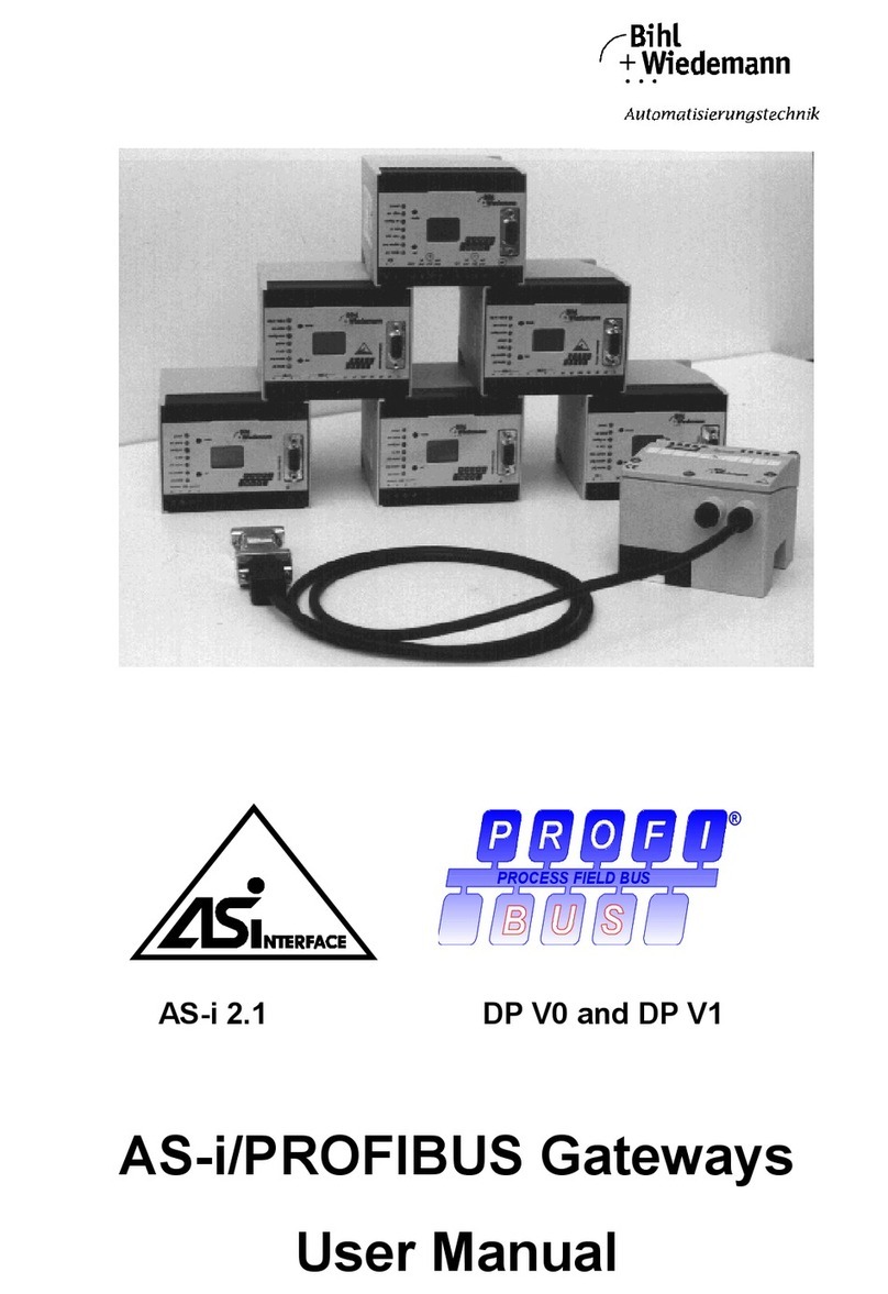
bihl+Wiedemann 1249 User manual
bihl+Wiedemann
bihl+Wiedemann 1062 User manual
bihl+Wiedemann
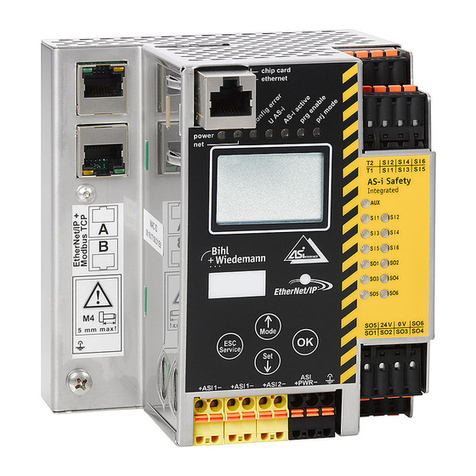
bihl+Wiedemann BWU3543 User manual
bihl+Wiedemann
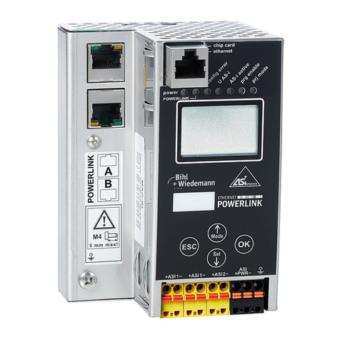
bihl+Wiedemann BWU3593 User manual
bihl+Wiedemann
bihl+Wiedemann BWU3857 User manual

bihl+Wiedemann
bihl+Wiedemann BWU3683 User manual
bihl+Wiedemann
bihl+Wiedemann 1116 User manual
bihl+Wiedemann
bihl+Wiedemann 1435 User manual
bihl+Wiedemann
bihl+Wiedemann AS-i/Modbus Gateway User manual
