Helmholz PN/CAN gateway User manual

Helmholz GmbH & Co. KG | Hannberger Weg 2 | 91091 Großenseebach | Germany
Phone +49 9135 7380-0 | Fax +49 9135 7380-110 | info@helmholz.de | www.helmholz.de
PN/CAN gateway, PROFINET/CAN Layer 2
Manual
Version 1 - 06/29/2017
Manual order number: 900-671-PNC01/en

Notes
All rights reserved, including those related to the translation, reprinting, and reproduction of this
manual or of parts thereof.
No part of this manual may be reproduced, processed, duplicated, or distributed in any form
(photocopy, microfilm, or any other methods), even for training purposes or with the use of
electronic systems, without written approval from Helmholz GmbH & Co. KG.
All rights reserved in the event of the granting of a patent or the registration of a utility model.
To download the latest version of this manual, please visit our website at www.helmholz.de.
We welcome all ideas and suggestions.
Copyright © 2017 by
Helmholz GmbH & Co. KG
Hannberger Weg 2, 91091 Großenseebach, Germany
Revision Record:
Version Date Change
1 6/29/2017 First version

PN/CAN gateway, PROFINET/CAN Layer 2 | Version 1 | 06/29/2017 3
Contents
1General............................................................................................................. 5
1.1 Target audience for this manual............................................................................................... 5
1.2 Safety instructions ................................................................................................................... 5
1.3 Note symbols and signal words ............................................................................................... 6
1.4 Intended use ........................................................................................................................... 7
1.5 Improper use........................................................................................................................... 7
1.6 Installation............................................................................................................................... 8
1.6.1 Access restriction ................................................................................................................. 8
1.6.2 Electrical installation ............................................................................................................ 8
1.6.3 Protection against electrostatic discharges ........................................................................... 8
1.6.4 Overcurrent protection ........................................................................................................ 8
1.6.5 EMC protection ................................................................................................................... 8
1.6.6 Operation ............................................................................................................................ 8
1.6.7 Liability ................................................................................................................................ 9
1.6.8 Disclaimer of liability............................................................................................................ 9
1.6.9 Warranty.............................................................................................................................. 9
2System overview.............................................................................................10
2.1 General/area of application ................................................................................................... 10
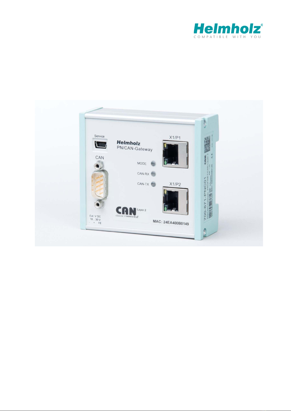
2.2 Properties of the PN/CAN gateway Layer 2............................................................................. 10
3Installation and removal................................................................................. 11
3.1 Installation position ............................................................................................................... 11
3.2 Minimum clearance............................................................................................................... 11
4Setup and wiring ............................................................................................12
4.1 EMC/safety/shielding............................................................................................................. 12
4.2 Wiring of the PN/CAN gateway.............................................................................................. 13
4.2.1 Voltage supply................................................................................................................... 13
4.2.2 CAN bus connection .......................................................................................................... 13
4.2.3 PROFINET connection ........................................................................................................ 13
4.2.4 USB interface ..................................................................................................................... 13
5CAN bus.......................................................................................................... 14
5.1 CAN bus wiring ..................................................................................................................... 14
5.2 CAN bus plug........................................................................................................................ 14

PN/CAN gateway, PROFINET/CAN Layer 2 | Version 1 | 06/29/2017 4
6Setup and use .................................................................................................15
6.1 Install GSDML file .................................................................................................................. 15
6.2 Configuring gateway............................................................................................................. 15
6.2.1 Configuring gateway ......................................................................................................... 16
6.3 Adding CAN frame................................................................................................................. 17
6.4 Automatically receiving CAN frames ...................................................................................... 17
6.5 Automatically transmitting CAN frames ................................................................................. 18
6.6 Controlled receiving of CAN frames....................................................................................... 18
6.7 Controlled transmission of CAN frames ................................................................................. 18
6.8 Assign the PN/CAN gateway a PROFINET name ..................................................................... 19
7Programming in the PLC ................................................................................20
7.1 Control and status ................................................................................................................. 20
7.1.1 Control (2 bytes outputs) .................................................................................................. 20
7.1.2 Status (6 bytes inputs) ....................................................................................................... 21
7.2 Controlled receiving of CAN frames....................................................................................... 22
7.3 Controlled transmission of CAN frames ................................................................................. 22
7.4 Receive channel (Rx-FIFO)...................................................................................................... 23
7.4.1 Set receive channel filter .................................................................................................... 23
7.4.2 Collecting frames from the receive channel........................................................................ 24
7.5 Transmission channel (Tx-FIFO) ............................................................................................. 25
7.5.1 Sending frames.................................................................................................................. 25
8LED-based diagnosis.......................................................................................27
9Technical data ................................................................................................28

PN/CAN gateway, PROFINET/CAN Layer 2 | Version 1 | 06/29/2017 5
1General
This operating manual applies only to devices, assemblies, software, and services of Helmholz GmbH
& Co. KG.
1.1 Target audience for this manual
This description is only intended for trained personnel qualified in control and automation
engineering who are familiar with the applicable national standards. For installation, commissioning,
and operation of the components, compliance with the instructions and explanations in this
operating manual is essential.
Configuration, execution, and operating errors can interfere with the proper operation of the PN/CAN
gateways and result in personal injury, as well as material or environmental damage. Only suitably
qualified personnel may operate the devices!
Qualified personnel must ensure that the application and use of the products described meet all the
safety requirements, including all relevant laws, regulations, provisions, and standards.
1.2 Safety instructions
The safety instructions must be observed in order to prevent harm to living creatures, material goods,
and the environment. The safety notes indicate possible hazards and provide information about how
hazardous situations can be prevented.

PN/CAN gateway, PROFINET/CAN Layer 2 | Version 1 | 06/29/2017 6
1.3 Note symbols and signal words
If the hazard warning is ignored, there is an imminent danger to life and health of people from electrical
voltage.
If the hazard warning is ignored, there is a probable danger to life and health of people from electrical
voltage.
If the hazard warning is ignored, people can be injured or harmed.
Draws attention to sources of error that can damage equipment or the environment.
Gives an indication for better understanding or preventing errors.

PN/CAN gateway, PROFINET/CAN Layer 2 | Version 1 | 06/29/2017 7
1.4 Intended use
The PN/CAN gateway integrates CAN devices into a PROFINET network.
All components are supplied with a factory hardware and software configuration. The user must carry
out the hardware and software configuration for the conditions of use. Modifications to hardware or
software configurations which extend beyond the documented options are not permitted and nullify
the liability of Helmholz GmbH & Co. KG.
The PN/CAN gateway may not be used as the only means for preventing hazardous situations on
machinery and systems.
Problem-free and safe operation of the PN/CAN gateway presumes proper transport, storage, setup,
assembly, installation, commissioning, operation, and maintenance.
The ambient conditions provided in the technical specifications must be adhered to.
The PV/CAN gateway has a protection rating of IP20 and must be installed in an electrical operating
room or a control box/cabinet in order to protect it against environmental influences. To prevent
unauthorized operation, the doors of control boxes/cabinets must be closed and possibly locked
during operation.
1.5 Improper use
The consequences of improper use may include personal injury to the user or third parties, as well as
property damage to the control system, the product, or the environment. Use the PN/CAN gateway only
as intended!

PN/CAN gateway, PROFINET/CAN Layer 2 | Version 1 | 06/29/2017 8
1.6 Installation
1.6.1 Access restriction
The modules are open operating equipment and must only be installed in electrical equipment
rooms, cabinets, or housings.
Access to the electrical equipment rooms, cabinets, or housings must only be possible using a tool or
key, and access should only be granted to trained or authorized personnel.
1.6.2 Electrical installation
Observe the regional safety regulations.
1.6.3 Protection against electrostatic discharges
To prevent damage through electrostatic discharges, the following safety measures are to be followed
during assembly and service work:
•Never place components and modules directly on plastic items (such as polystyrene, PE film) or in
their vicinity.
•Before starting work, touch the grounded housing to discharge static electricity.
•Only work with discharged tools.
•Do not touch components and assemblies on contacts.
1.6.4 Overcurrent protection
Overcurrent protection isn't necessary as the PN/CAN gateway transports no load current. The power
supply of the PN/CAN gateway electronics is to be secured externally with a fuse of maximum 1 A
(slow-blowing).
1.6.5 EMC protection
To ensure electromagnetic compatibility (EMC) in your control cabinets in electrically harsh
environments, the known rules of EMC-compliant configuration are to be observed in the design and
construction.
1.6.6 Operation
Operate the PN/CAN gateway only in flawless condition. The permissible operating conditions and
performance limits must be adhered to.
Retrofits, changes, or modifications to the device are strictly forbidden.
The PN/CAN gateway is a piece of operating equipment intended for use in industrial plants. During
operation, all covers on the unit and the installation must be closed in order to ensure protection
against contact.

PN/CAN gateway, PROFINET/CAN Layer 2 | Version 1 | 06/29/2017 9
1.6.7 Liability
The contents of this manual are subject to technical changes resulting from the continuous
development of products of Helmholz GmbH & Co. K. In the event that this manual contains
technical or clerical errors, we reserve the right to make changes at any time without notice.
No claims for modification of delivered products can be asserted based on the information,
illustrations, and descriptions in this documentation. Beyond the instructions contained in the
operating manual, the applicable national and international standards and regulations must also be
observed in any case.
1.6.8 Disclaimer of liability
Helmholz GmbH & Co. KG is not liable for damages if these were caused by use or application of
products that was improper or not as intended.
Helmholz GmbH & Co. KG assumes no liability for any printing errors or other inaccuracies that may
appear in the operating manual, unless there are serious errors of which Helmholz GmbH & Co. KG
was already demonstrably aware.
Beyond the instructions contained in the operating manual, the applicable national and
international standards and regulations must also be observed in any case.
Helmholz GmbH & Co. KG is not liable for damage caused by software that is running on the user’s
equipment which compromises, damages, or infects additional equipment or processes through the
remote maintenance connection, and which triggers or permits unwanted data transfer.
1.6.9 Warranty
Report any defects to the manufacturer immediately after discovery of the defect.
The warranty is not valid in case of:
•Failure to observe these operating instructions
•Use of the device that is not as intended
•Improper work on and with the device
•Operating errors
•Unauthorized modifications to the device
The agreements met upon contract conclusion under “General Terms and Conditions of Helmholz
GmbH & Co. KG” apply.

PN/CAN gateway, PROFINET/CAN Layer 2 | Version 1 | 06/29/2017 10
2System overview
2.1 General/area of application
The PN/CAN gateway connects a CAN network into a PROFINET network. Any CAN messages in 11
bit or 29 bit format (CAN 2.0A / CAN 2.0B) can be integrated into the IO area of a PROFINET CPU.
2.2 Properties of the PN/CAN gateway Layer 2
The PN/CAN gateway CAN Layer 2 has the following properties:
•PROFINET IO as defined in IEC 61158-6-10
•Up to 512 PROFINET slots
•Configuration using GSDML file
•Integrated two-port Ethernet switch
•Full-duplex transmission rate of 100 Mbps
•Media redundancy (MRP client)
•CAN 2.0A (11 bit identifier) and
CAN 2.0B (29 bit identifier) in accordance with ISO 11898-2
•Up to 1 Mbps CAN bit rate
•Automatic and controlled reception and transmission objects for frames with projected CAN ID
•Receiving channel FIFO for the reception of any CAN frames
•Transmission channel FIFO for the transmission of any CAN frames
•No handling blocks or parameterization software necessary
•24 V DC power supply
•3 LEDs, bi-color
•USB device interface for online diagnosis and firmware update

PN/CAN gateway, PROFINET/CAN Layer 2 | Version 1 | 06/29/2017 11
3Installation and removal
Bus connections are interrupted when the PN/CAN gateway is switched off!
Before commencing with any kind of work on the PN/CAN gateway, ensure that no impermissible
disruptions of connected systems occur following interruption of the bus connections.
Installation must be carried out according to VDE 0100/IEC 364 and performed in accordance with
applicable national standards. The PN/CAN gateway has protection rating IP20. If a higher protection
rating is required, the system must be installed in a housing or control cabinet. In order to ensure safe
operation, the ambient temperature must not exceed 60 °C.
3.1 Installation position
The PN/CAN gateway can be installed in any position. The front plate must be accessible in order to
plug in bus lines.
3.2 Minimum clearance
It is recommended to adhere to the minimum clearances specified when installing devices. Adhering
to these minimum clearances will ensure that:
•The modules can be installed and removed without having to remove any other system
components
•There will be enough space to make connections to all existing terminals and contacts using
standard accessories
•There will be enough space for cable management systems (if needed)

PN/CAN gateway, PROFINET/CAN Layer 2 | Version 1 | 06/29/2017 12
4Setup and wiring
4.1 EMC/safety/shielding
The PN/CAN gateway complies with EU Directive 2004/108/EC (“Electromagnetic Compatibility”).
One effective way to protect against disturbances caused by electromagnetic interference is to shield
electric cables, wires, and components.
When setting up the system and routing the required cables, make sure to fully comply with all
standards, regulations, and rules regarding shielding. Precisely observe the corresponding texts of the
PROFIBUS user organization for setting up PROFINET and the setup guidelines for the CAN bus. All work
must be done professionally!
Shielding faults can result in serious malfunctions, including the system’s failure.
To ensure electromagnetic compatibility (EMC) in your control cabinets in electrically harsh
environments, the following EMC rules are to be observed in the design:
•All metal parts of the cabinet are to be connected with each other over a large area with good
conductivity (no paint on paint). Where necessary, use contact washers or serrated washers.
•The cabinet door must be connected to the ground straps (top, middle, bottom) over as short a
distance as possible.
•Signal cables and power cables are to be laid separated spatially by a minimum distance of 20 cm
from each in order to avoid coupling paths.
•Run signal lines only from one level into the cabinet if possible.
•Unshielded cables in the same circuit (outgoing and incoming conductors) must be twisted if
possible.
•Contactors, relays, and solenoid valves in the closet, or in adjacent cabinets if applicable, must be
provided with quenching combinations; e.g., with RC elements, varistors, diodes.
•Do not lay wires freely in the closet; instead, run them as closely as possible to the cabinet housing
or mounting panels. This also applies to reserve cables. These must be grounded on at least one
end, and it is better if they are grounded at both ends (additional shielding effect).
•Unnecessary line lengths should be avoided. Coupling capacitances and inductances are kept low
this way.
•Analog signal lines and data lines must be shielded.

PN/CAN gateway, PROFINET/CAN Layer 2 | Version 1 | 06/29/2017 13
4.2 Wiring of the PN/CAN gateway
4.2.1 Voltage supply
The PN/CAN gateway is supplied with 24 V DC voltage via the 3-pin power supply plug (V+, GND,
FE).
4.2.2 CAN bus connection
Pin SubD plug CAN bus
1 -
2 CAN low
3
CAN GND
4
-
5 -
6
-
7
CAN high
8 -
9
-
PN/CAN gateway contains no terminating resistor for use at the end of a CAN bus network segment! To
this purpose use CAN bus plugs with integrated terminating resistors (see chapter 5.2).
4.2.3 PROFINET connection
Pin Signal RJ45 plug PROFINET Color Wire pair
1 TD+ Transmission data + Yellow 1
2
TD-
Transmission data -
Orange
1
3
RD+
Receive data +
White
2
4 - - - -
5
-
-
-
-
6
RD- Receive data - Blue 2
7
-
-
-
-
8
-
-
-
-
4.2.4 USB interface
The service USB interface is currently only required for the firmware update and for diagnostics in the
event of support.

PN/CAN gateway, PROFINET/CAN Layer 2 | Version 1 | 06/29/2017 14
5CAN bus
CAN bus (Control Area Network) is an international and open fieldbus standard for building,
manufacturing, and process automation applications. CAN bus communications are defined in
standard ISO 11898-2.
5.1 CAN bus wiring
A CAN bus cable requires at least three wires: CAN high, CAN low, and CAN ground. Only linear bus
topologies are allowed, A terminating resistor of 120 ohms must be connected between CAN high and
CAN low at both ends of the CAN bus cable. The PN/CAN gateway has no installed bus terminating
resistor.
The maximum cable lengths will depend mainly on the bit rate being used.
Bit rate Bus length Bit time
1 Mbps 30 m 1 µs
800 kbps
50 m
1.25 µs
500 kbps
100 m
2 µs
250 kbps
250 m
4 µs
125 kbps
500 m
8 µs
50 kbps 1500 m 20 µs
The cable lengths specified above should only be used as reference values. The maximum cable length
will also depend on the number of connected participants, on the use and the number of repeaters,
and on the cable type.
5.2 CAN bus plug
Helmholz GmbH & Co. KG offers an extensive range of CAN bus connectors that can be used with the
PN/CAN gateway. All CAN bus connectors come with a terminating resistor that can be switched on
and off.

PN/CAN gateway, PROFINET/CAN Layer 2 | Version 1 | 06/29/2017 15
6Setup and use
6.1 Install GSDML file
The GSDML file can be found on the accompanying CD or in the download area of the "PN/CAN
gateway Layer 2" at www.helmholz.de.
6.2 Configuring gateway
The PN/CAN gateway can be found in the hardware under "PROFINET IO Other field devices
Gateway Helmholz PN/CAN gateways". Add the "PN/CAN gateway CAN Layer 2" to the project and
connect it with your PROFINET network.
By calling up the object properties, the PN/CAN gateway should be assigned a unique PROFINET
name and the IP address be checked for plausibility.
The name of the configured device must later be assigned to the physical device (see Ch. 6.8).

PN/CAN gateway, PROFINET/CAN Layer 2 | Version 1 | 06/29/2017 16
6.2.1 Configuring gateway
The first slot entry after the ports is the slot for the parameters.
CAN bit rate: 10, 50, 100, 125, 250, 500, 800 Kbps, and 1 Mbps are available as bit rates.
CAN identifier type: The PN/CAN gateway can process and transmit CAN frames with either 11 bit
identifiers or with 29 bit identifiers.
Length of the receive channel FIFO: Maximum number of frames that can be stored temporarily in
the receive channel. Details for the use of the receive channel are explained in chapter 7.4 "Receive
channel (Rx-FIFO)".
Filter mask (dec.) / Filter code (dec.): Filter for the frames that should be accepted by the receive
channel FIFO. Details for the use of the receive channel are explained in chapter 7.4 "Receive channel
(Rx-FIFO)".
Allow overwriting of the receive FIFO: When the reception channel FIFO is full, because the
received frames can't be picked up quickly enough by the PLC, this option can be used to set whether
new frames should be rejected or whether old frames should be overwritten. Details for the use of the
reception channel are explained in chapter 7.4 "Receive channel (Rx-FIFO)".
Length of the transmission channel FIFO: The size of the transmission channel FIFO can be set
between 1 and 255 frames. Details for the use of the transmission channel are explained in chapter 7.5
"Transmission channel (Tx-FIFO)".
Repetition time for transmission channel (ms): The time for the cyclical transmission of a CAN
frame via the transmission channel can be set here.
Carry out a device reset for PLC stop: When the PN/CAN gateway receives the "PLC in stop" signal
via PROFINET, it can carry out an internal reset in order to ensure a defined basic status for a restart of
the PLC.

PN/CAN gateway, PROFINET/CAN Layer 2 | Version 1 | 06/29/2017 17
6.3 Adding CAN frame
The PN/CAN Gateway Layer 2 can transmit and receive CAN frames with 1 to 8 bytes of data and any
CAN-IDs. A module with the CAN identifier must be configured in the slots of the PN/CAN gateway
for each anticipated CAN frame and each CAN frame to be transmitted.
There are two types of CAN frames:
automatic receiving/transmission and controlled receiving/transmission.
In the case of automatic transmission, the CAN frame is transmitted as soon as the output data of
the frame changes. Repeat transmission of the same data is thus not possible.
In the case of the automatic receive of CAN frames, the data of the most recently received CAN frame
is always found in the input data. If a CAN frame with identical data is received several times, this
can't be recognized in the PLC.
In the case of controlled transmission and the controlled receive of CAN frames the PLC program
has direct control over each telegram through control and status bits.
6.4 Automatically receiving CAN frames
In the case of the automatic receive of CAN frames, the data of the most
recently received CAN frame is always found in the input data.
Each configured CAN frame has a clear CAN identifier.
If two reception objects with the same CAN identifier are being configured,
that results in a configuration error.
A CAN frame always has a fixed data length. In the case of automatic reception, CAN frames with 1 to
8 bytes can be configured.
If a CAN frame is received that has the correct CAN identifier but a false data length, the frame is
rejected and the data is not forwarded to the PLC!
CAN frames with differing data lengths can be processed with the receiving channel (Rx-FIFO).

PN/CAN gateway, PROFINET/CAN Layer 2 | Version 1 | 06/29/2017 18
6.5 Automatically transmitting CAN frames
In the case of automatic transmission of a CAN frame, a frame is always
sent to the CAN bus when the output data of the module changes.
Each configured CAN frame has a clear CAN identifier.
In the case of automatic transmission, CAN frames with 1 to 8 bytes can be configured. The
transmission of CAN frames with a variety of data lengths can be carried out with the transmission
channel (Tx-FIFO).
6.6 Controlled receiving of CAN frames
In the case of the controlled receive of CAN frames, the reception of each
frame must be acknowledged in the PLC program.
In the case of controlled reception, CAN frames with 0 to 8 bytes can be
configured. An RTR frame can also be received.
If a CAN frame is received that has the correct CAN identifier but a false data
length, the frame is rejected and the data is not forwarded to the PLC!
If two reception objects with the same CAN identifier are being configured, that results in a
configuration error.
6.7 Controlled transmission of CAN frames
In the case of controlled transmission of a CAN frame, the PLC can only
directly trigger the transmission of a CAN frame through a control bit,
irrespective of whether the transmission data has changed.
In the case of controlled transmission, CAN frames with 0 to 8 bytes can be
configured. An RTR frame can also be transmitted.

PN/CAN gateway, PROFINET/CAN Layer 2 | Version 1 | 06/29/2017 19
6.8 Assign the PN/CAN gateway a PROFINET name
When the configuration of the PN/CAN gateway has been completed in the hardware configurator, it
can be loaded into the PLC.
In order that the PN/CAN gateway can be found on the PROFINET of the PLC (the PROFINET
controller), the PROFINET name and possibly the IP address must be set.
One possibility for this is the function "Process Ethernet participant" in the Simatic Manager. With
the "Browse…" button, the network can be browsed for PROFINET participants.
The clear identification of the PN/CAN gateway is ensured here by the MAC address of the device.
The assigned name must agree with the name established in the hardware configurator (see Ch. 6.2.1).
If the PN/CAN gateway has been assigned the correct PROFINET name, it is recognized by the PLC and
configured.
When the configuration has run correctly, the blue "Mode" LED should blink.

PN/CAN gateway, PROFINET/CAN Layer 2 | Version 1 | 06/29/2017 20
7Programming in the PLC
No handling blocks are required for operation of the PN/CAN gateway in the PLC. The control and
status query of the PN/CAN gateway can be carried out directly via the I/O image.
7.1 Control and status
No handling blocks for simple operation are required in the PLC. The control and status query of the
PN/CAN gateway can be carried out directly via the I/O image.
In order to switch to normal operation, the value 3 must be written into the "Control" output word.
7.1.1 Control (2 bytes outputs)
Byte/bit 7 6 5 4 3 2 1 0
Out 0 - Reset - - - - - -
Out 1 - - - - - - Mode
The mode bits are used for the status control of the PN/CAN gateway.
INIT (0) = CAN controller is at the bus, no frames are transmitted, received frames are discarded;
outputs/inputs are set to zero; FIFOs are deleted.
The INIT (0) status is automatically active in the event of a PROFINET network cancellation or
stoppage of the PLC.
PASSIV (1) = CAN Controller is at the bus; received frames are discarded, no frames are transmitted;
error counters are transmitted to the PLC; FIFOs are maintained and can be operated; Rx-FIFO can be
read until it is empty; Tx-FIFO can be described, but no frames are transmitted; controlled
transmission modules can be operated; data from automatic receiver modules remain frozen
RX-Only (2) = Only the CAN reception is processed. No CAN frames are transmitted.
RX-TX (3) = Normal operation with transmitter and receiver.
Reset: Carrying out a user reset. After setting the bit, one must wait for the bit 6 in the status byte 0.
The PN/CAN gateway is in the INIT mode following the reset. The reset bit in status control can now
be reset.
In order to change to the desired operating mode, it is permitted to directly activate the desired mode.
Other manuals for PN/CAN gateway
3
This manual suits for next models
1
Table of contents
Other Helmholz Gateway manuals

Helmholz
Helmholz CANopen User manual

Helmholz
Helmholz WALL IE 700-860-WAL01 User manual

Helmholz
Helmholz PN/CAN Gateway Layer 2 User manual

Helmholz
Helmholz WALL IE Compact User manual

Helmholz
Helmholz 700-672-PNC01 User manual

Helmholz
Helmholz WALL IE User manual

Helmholz
Helmholz PN/CAN gateway User manual

Helmholz
Helmholz NETLink User manual

Helmholz
Helmholz NETLink 700-881-MPI21 User manual

Helmholz
Helmholz 700-671-PNC01 User manual