Bikefun ROCK MACHINE RM-E02 User manual
SERVICE
MANUAL
ROCK MACHINE
RM-E02

SERVICE MANUAL
ROCK MACHINE
Rock Machine would like to congratulate you on the purchase of your new product. We place
great emphasis on the choice of materials and their processing so as to ensure the highest
quality of our products, a long service life and great functionality. Our name is a symbol of a
captivating design, concept and appearance.
To enjoy unlimited riding pleasure with your high-quality Rock Machine product
for many years to come, it is necessary to observe certain rules defined and specified in the
Service Manual. You have received the Operating Manual with your bike.
Rock Machine supplies high-quality bicycles exclusively for specialized shops. These products
are already partially pre-assembled.
The final assembly of the bike can only be carried out by an authorized Rock Machine dealer.
This particularly applies to the basic configuration of suspension components, the front
and back derailleurs and braking systems. This will ensure maximum safety when using the
product.
WARNING
WARNINGS RELATED TO
MECHANICAL WORK
Specialized skills and tools are required to
configure and tune the bike. These tasks
should only be carried out by employees
at an authorized service station. Riding a
bike that has not been correctly configured
and assembled can be dangerous. Even a
seemingly minor deficiency, such as a loose
screw, can cause a crucial part to break over
time and the loss of control of the bike, leading
to an accident. Therefore, we recommend that
you leave any repairs and maintenance for your
bicycle to an authorized service centre. Your
safety depends on the correct maintenance
of the bike. Employees of authorized service
stations have special qualifications and know-
how.
WARNING
Any adjustments and modifications can lead
to the frame, fork or other parts becoming
unsafe. The use of an unapproved component
or the incorrect assembly of parts can lead
to excessive wear and tear of the bike or its
parts. Adjustments to the frame, fork or other
components can have a negative impact on
the handling of the bike and may lead to a
fall. Do not grind off, drill or file any parts; do
not remove backup safety elements, do not
install incompatible forks and do not make
any other similar unauthorized changes.
Before you install any accessories on your
bicycle, or replace any part, always consult the
service centre staff to make sure the particular
accessory or part is compatible and safe to
use.
Type-3 operating conditions
Riding on trails, crossing small obstacles and technical courses of
medium difficulty as well as stretches where the tyres do not make
contact with the ground for a short period of time; jumps and drops not
exceeding 61 cm (24").
BIKE CATEGORY
e-Blizz
Mountain bikes are equipped with a rear suspension and are constructed for “standard”,
“racing”, “cross-country” or “singletrack-trail” rides, assuming adherence to type-3 operating
conditions:
PREVENTING DAMAGE
If you are transporting the bike in a box, make sure that the bike is kept safe, for instance by
using a soft foam cover. Make sure that there are no foreign items or that excessive pressure
or force from these items cannot damage the frame. Please keep in mind that the warranty
does not apply to damage caused during transit.
WARNING
The warranty may be voided if the service intervals and prescribed torques are not adhered to.
SERVICE INTERVALS
• Large-scale service – at a service centre, 1× per year or after 200 hours of riding.
• Check the tightening of moving parts before and after each ride. The prescribed torques
of individual joints (see the diagram below) must be strictly observed.
• Bearings and pivots should be lubricated 1× per half a year.
• Consult your dealer about the exact service plan and maintenance schedule of your
bicycle. The dealer shall propose the schedule depending on the model of your bicycle
and the way you use it. The service intervals stated above are the recommended
maximum intervals for regular bicycle maintenance, i.e. they cannot be extended under
any circumstance. If you ride your bicycle more intensively, or if your dealer advises
you to, we recommend that you shorten the intervals and extend the scope of tasks
carried out. For example, if you ride your bicycle in adverse climatic conditions, over hard
terrain or if you have equipped your bicycle with specific components with a different
service interval and scope of regular maintenance stated by their manufacturer (exact
instructions regarding the service of particular components will be provided by your
dealer).
REAR SHOCK AND FORK
ADJUSTMENT
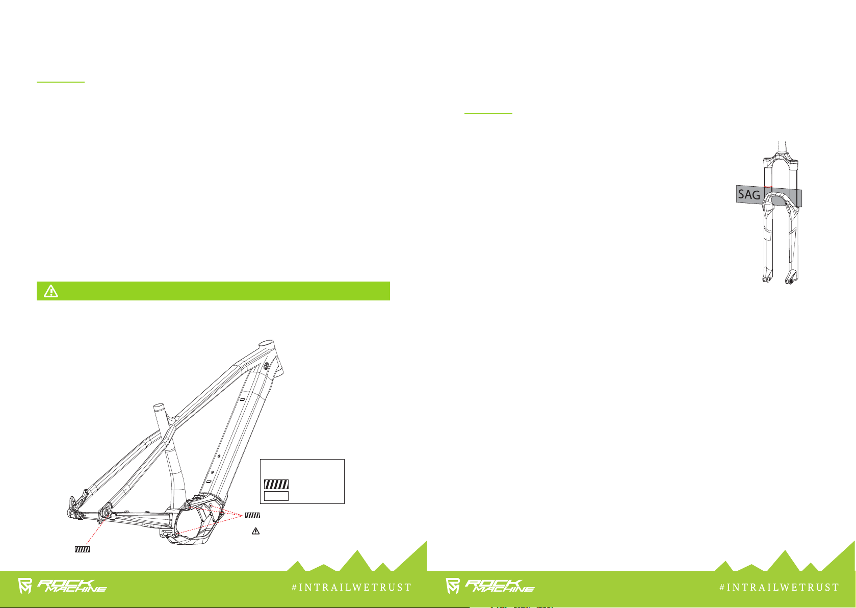
CONFIGURING THE FORK AND REAR SHOCK STIFFNESS
(SAG)
• Depending on your riding style and the way you use your bike,
the sag should range between 20-30%.
• This value is specified directly on the shock absorber body or
on the inner side of the fork right-hand leg.
• The fork and the rear shock must always be unlocked while
being configured.
• Move the rubber indication ring located on the inner fork leg
and the damper body to the dust cap.
• Sit on the bicycle with your full weight and then get off it
carefully, without rocking the bike.
• Check the position of the ring and make sure that the fork and
the rear shock are set in accordance with the values stated
in the chart (see below), or adjust the pressure in the fork as
needed.
SETTING THE REBOUND FOR THE FORK
• Rebound is a term used to describe the speed of the fork returning to its original position
after absorbing a shock. The control for adjusting the rebound is usually located on the
bottom side of the fork leg.
• When sitting on the saddle, ride off an edge of approx. 10 -15 cm in height.
• If the fork rocks 1 or 2 times, the rebound is set correctly.
• If the fork rocks more than 3 times, the rebound is too fast.
• If the fork does not rock at all, the rebound is too slow.
4 Nm (no laser marking)
MOTOR SCREWS
10 - 12.5 Nm
It is necessary to tighten the
screws on the right side rst,
then the screws on the left side!
Blue nylock
No nylock
THREAD LOCKING AGAINST
SPONTANEOUS RELEASE
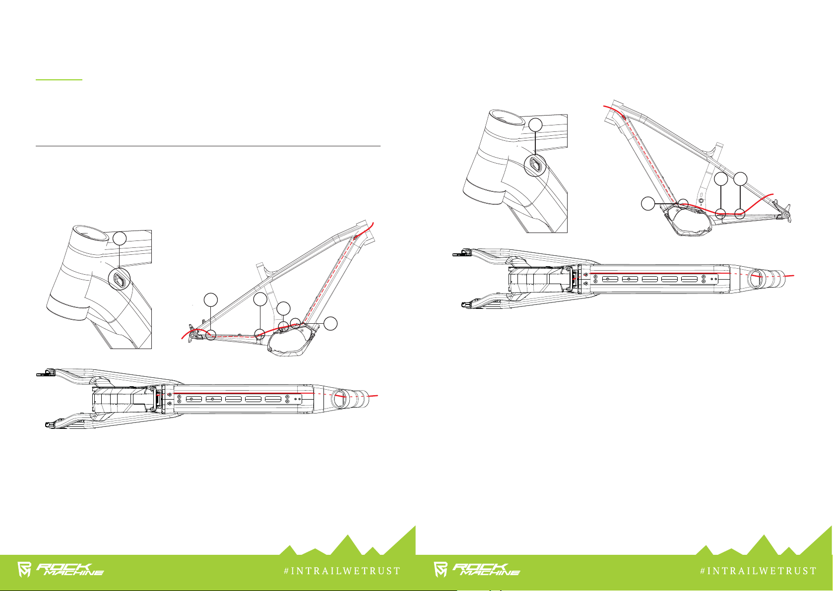
1 REPLACING THE REAR DERAILLEUR CABLE
1.1 Slide the old cable out from the guide in the frame.
1.2 Slide a new cable in the frame through the hole A1 and pull it out through the hole A2.
1.3 Fix the cable to the hitch A3 using a tying strip.
1.4 Slide the cable through the hole A4 in the rear swingarm and pull it out through the hole A5.
2 REPLACING THE HYDRAULIC HOSE OF THE REAR BRAKE
2.1 Slide the old hose out from the guide in the frame.
2.2 Slide a new hose in the frame through the hole A1 and pull it out through the hole A2.
2.3 Fix the cable to the hitch B1.
2.4 Fix the cable to the hitches B2 and B3 using tying strips.
SERVICE
REPLACING THE CABLES AND HOSES
Ducts are made using guiding tunnels inside of the bicycle frame. The ducts allow easy and
quick replacement of cables and hoses within their full length without need to break them.
A1
A2
A4
A3
A5
A1
B2
B1
A2
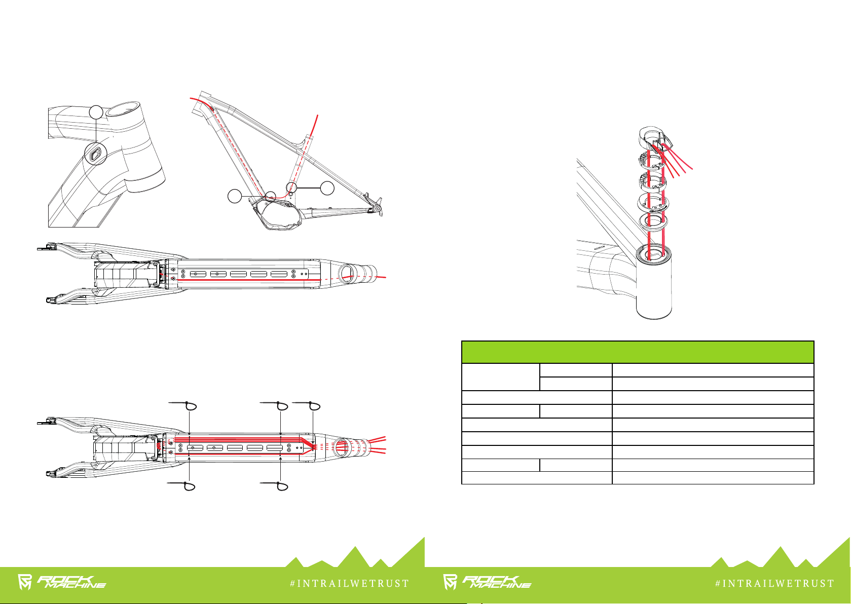
3 REPLACING THE TELESCOPIC SEATPOST CABLE
3.1 Slide the old cable out from the guide in the frame.
3.2 Slide a new cable in the frame through the hole C1 and pull it out through the hole A2.
3.3 Slide the cable in through the hole C2 and pull it through the seatpost tube.
C1
C1
A2
4 FASTENING THE CABLES, HYDRAULIC HOSE AND DISPLAY CABLE
4.1 Fasten the cables, hydraulic hose and display cable to the docking
station bar using tying strips.
4.2 Tighten the telescopic seatpost cable so that it would remain movable.
4.3 Put the foam Jagwire SFA07A5M sleeve on the cables, hydraulic hose and display cable in
length only up to the headset.
5 PULLING THE CABLES, HYDRAULIC HOSE AND DISPLAY CABLE THROUGH
THE HEADSET AND SPACER RINGS
5.1 Pull the cables, hydraulic hose and display cable through the headset bearing lid and spacer
rings so that the telescopic seatpost cable and display cable would be positioned on the right-
hand side when viewing from the front (1).
5.2 Pull the shifting cable and rear brake hydraulic hose through so that they would be positioned
on the left-hand side when viewing from the front (2).
1
2
COMPATIBILITY
Brake Rotors Front Ø 180 - 203 mm
Rear Ø 180 - 203 mm
Tyre max. 29” x 2,6”
Chainring 1× max. number of teeth 36
Headset BC 1-1/8” *1.5” ACROS AZX-220 ZS44, BLOCK-LOCK
Bottom Bracket Shimano STePS Middle Drive Unit
Seatpost Clamp Ø 34.9 mm
Seatpost Ø 30.9 mm min. insertion 100 mm
Rear Thru-axle Shimano BOOST 12 x 148 mm
SMART TIPS
To improve handling and comfort and to prevent defects, we recommend installing a tubeless system.
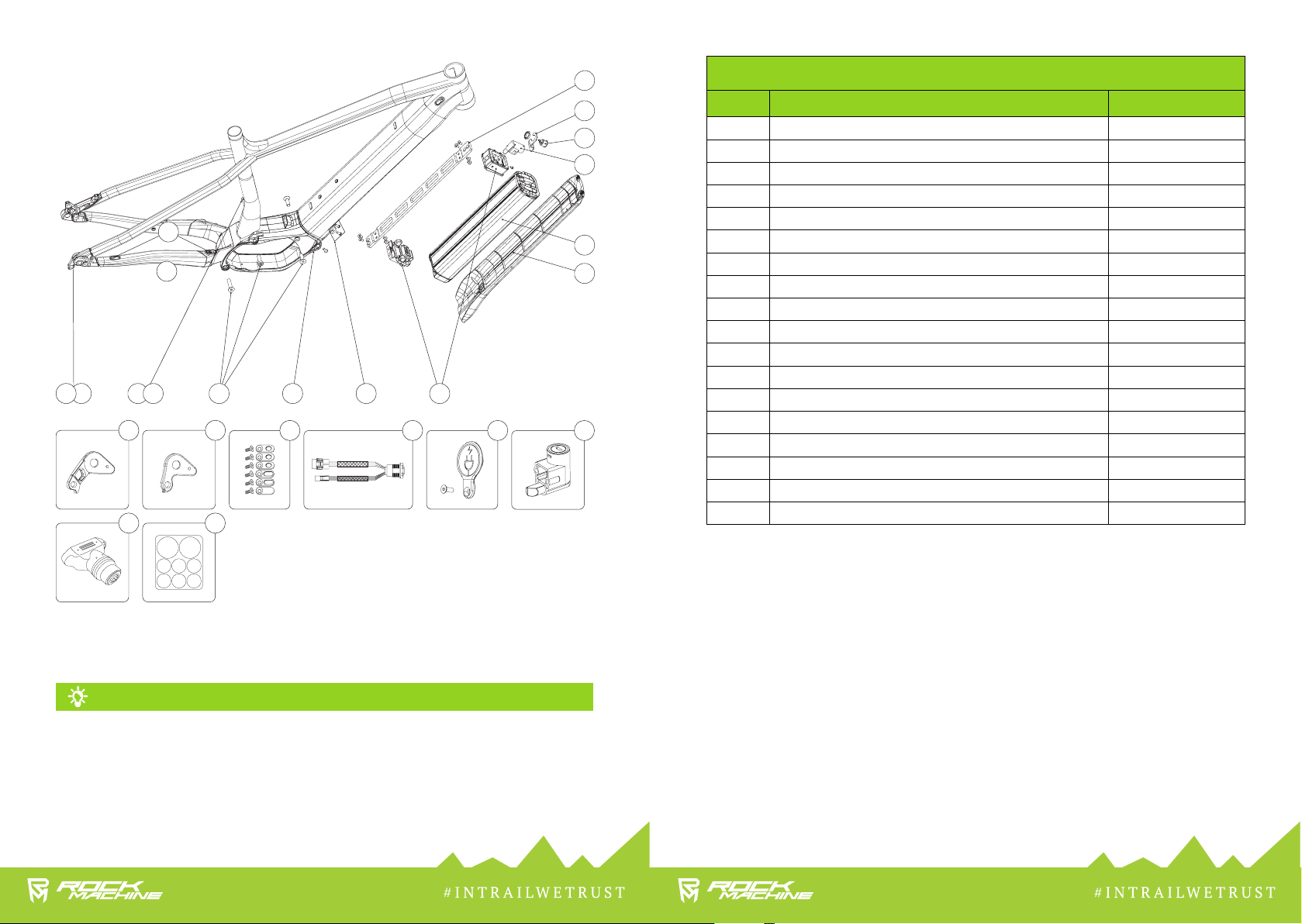
ORIGINAL ACCESSORIES
ART. NO. DESCRIPTION BFI PRODUCT CODE
1 CHAIN STAY PROTECTOR 087.8001.00001-196
2 SHIMANO DIRECT MOUNT DERAILLEUR HANGER 013.0002.00089-377
3 SRAM/SHIMANO DERAILLEUR HANGER 013.0002.00137-372
4 INTERNAL CABLE ROUTING SET 013.0003.00095-372
5 SKID PLATE 013.0019.00001-372
6 MOTOR SCREW SET 598.1303.00022
7 CHARGER 095.0008.00019-396
8 CHARGER COVER 095.0010.00023-372
9COVER LOCKHOLD 013.0017.00016-372
10 DOCK PLATE 095.0010.00018-372
11 POWER SWITCH HANGER 095.0010.00019-372
12 BATTERY MOUNT 095.0013.00022-396
13 BATTERY MOUNT LOCK 098.0002.00093-276
14 BATTERY 503 WH 095.0003.00073-396
15 BATTERY COVER 013.0020.00003-196
16 POWER BUTTON 095.0016.00003-396
17 CHARGING ADAPTER 095.0012.00007-396
18 PROTECTION DECAL SET 087.7000.00009-196
4 7 8
18
32 6
4
5 9 12
15
78
10
11
16
14
13
1
2 3 13
17

#INTRAILWETRUST
Rock Machine is a registered trade mark of
BIKE FUN International
Areál Tatry 1445/2
742 21 Kopřivnice
www.rockmachine.us
Table of contents
Other Bikefun Bicycle Accessories manuals


