BIKESTAR City User manual

Assembly Instructions for
City Bicycles
2
Dear customer,
Congratulations on the purchase of your new bicycle from our online bike shop! Our expert bike mechanics have already comple-
tely assembled your new bicycle, made all the necessary ne adjustments (such as shift and brake adjustments) and carried out a
thorough check of all of its functions.
You will notice that we have used specially-developed protective packaging on your new bike, for the best possible protection
during the delivery process. We have also dismantled the saddle, pedals and the front wheel to protect these components during
transport.
Before your rst ride, all you have to do is install the front wheel, adjust the handlebars and mount the saddle and pedals. These
steps are all quite easy and quick to undertake – without any prior experience or knowledge.
You’ll nd the tools and components you need safely stored in your bike box. This assembly guide will take you step-by-step, from
the unpacking to your very rst ride.
We wish you a lot of fun with your new bike!
Watch out for the following symbols:
ATTENTION NOTE
The steps described over the following pages may somewhat dier from the steps required for your specic bicycle model. The
image material used shows the typical work steps that are usually required.
All of our bike models come with an EU standard brake setup. This setup will need to be reversed to comply with UK cycling
standards.
Bicycles without lighting systems do not comply with the provisions of the Road Vehicle Lighting Regulations once the sun has set.
Please note that unless satisfactory lights and reectors are tted, the use of these models is not permitted on public roads at night.
Each individual bike has a stamped number for identication. Please make a record of the frame number of your new bike.
The frame number is usually found in the bottom bracket area. Depending on the manufacturer, however, the position of the
frame number may dier (seat tube, head tube or fork end). Write down your frame number on the invoice.
Important notes
Introduction

3Contents
1. Delivery
2. Front wheel assembly
2.1 Preparing the front wheel & fork
2.2 Preparing the brakes
2.3 Installing the front wheel
2.4 Securing the front wheel
2.5 Installing the brakes
2.6 Functional check
3. Adjusting/Installing the handlebars & stem
3.1 Adjusting Ahead stem & headset bearings
3.2 Adjusting quill stem on threaded headset
3.3 Adjusting the handlebars
3.4 Re-mounting dismounted handlebars
4. Mounting the saddle & seatpost
5. Fitting the pedals
6. Final check & test drive
7. Maintaining the bicycle
Contents
4Delivery
Unpacking all the components from the bike box:
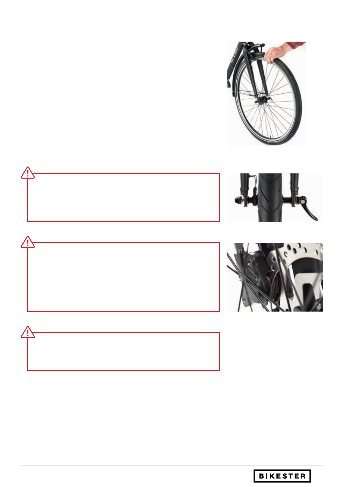
Open the bicycle box and remove the transport safety device on the rear wheel. On
some models, the front wheel is secured to the handlebars with a cable tie. Please
also remove this cable tie. Remove the front wheel from the box. For a disc brake
front wheel, please avoid touching the brake disc. ( g. 2)
1. Delivery
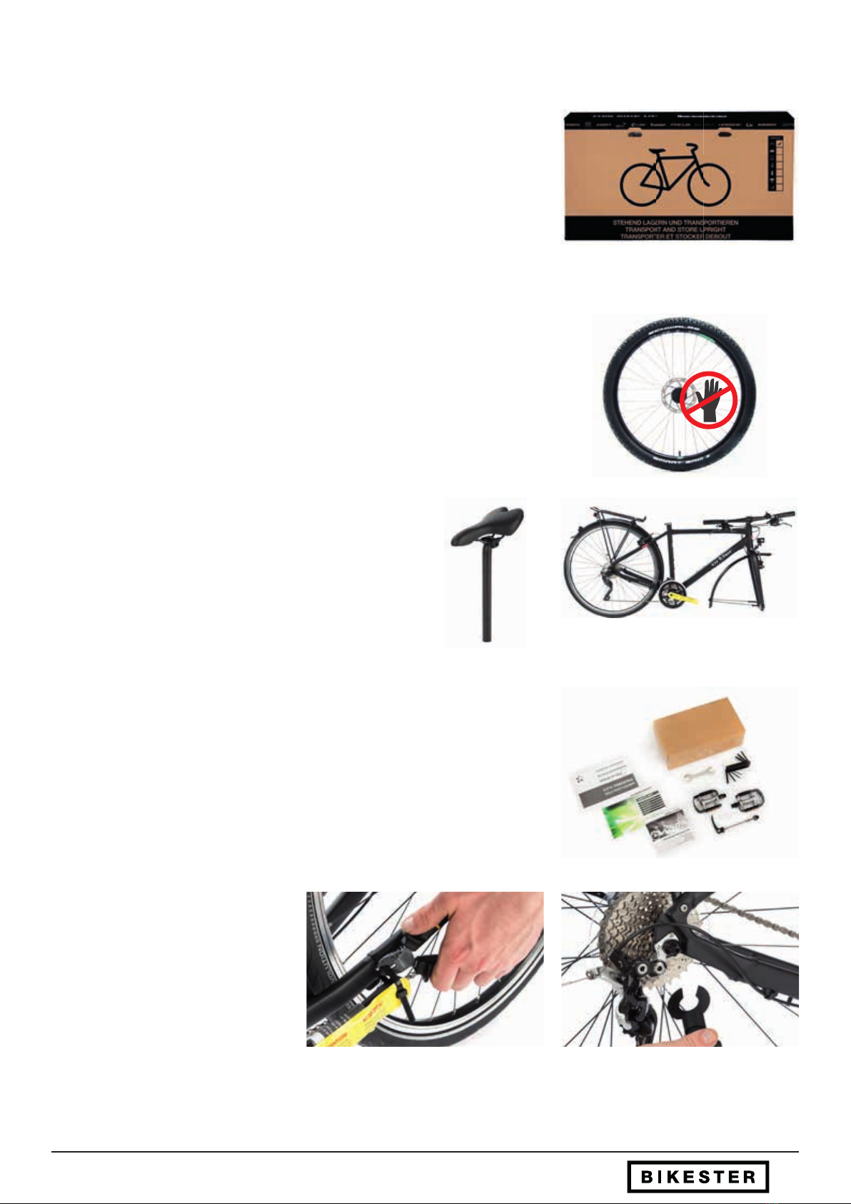
What is in the package? ( g. 1)
1 x assembled, checked and safely packaged bicycle
1 x separate front wheel
1 x combination saddle/seatpost
1 x accessory box containing an instruction manual, tools, accessories and pedals (if
included with your bike model)
g. 2
g. 1
g . 3 g . 4
g . 5
Remove the seat post with the saddle and the frame with the
rear wheel. ( g. 3-4)
Remove the accessory box. In this you will nd the manufacturer‘s manual, the
included mounting tool and any accessories such as pedals and front-wheel quick
releases. ( g. 5)
g . 7
g . 6
Carefully remove packing material from
the frame and fork as well as the trans-
port safety devices on the crank and the
derailleur. ( g. 6-7)
5Front Wheel Assembly - Preparing the front wheel and fork - Quick release
After unpacking all the components, the front wheel should be installed to place the new bike on its "feet“ for all further work. So
that the front wheel can be mounted correctly into the fork, several steps must rst be taken on the front wheel, fork and brakes.
Below you will nd the necessary instructions needed for your specic brake and front wheel type.
2.1 Preparing the front wheel and fork
Please nd and follow the appropriate section for your model:
2. Front wheel assembly
g. 3
g. 2
g. 4
g. 1
A
B
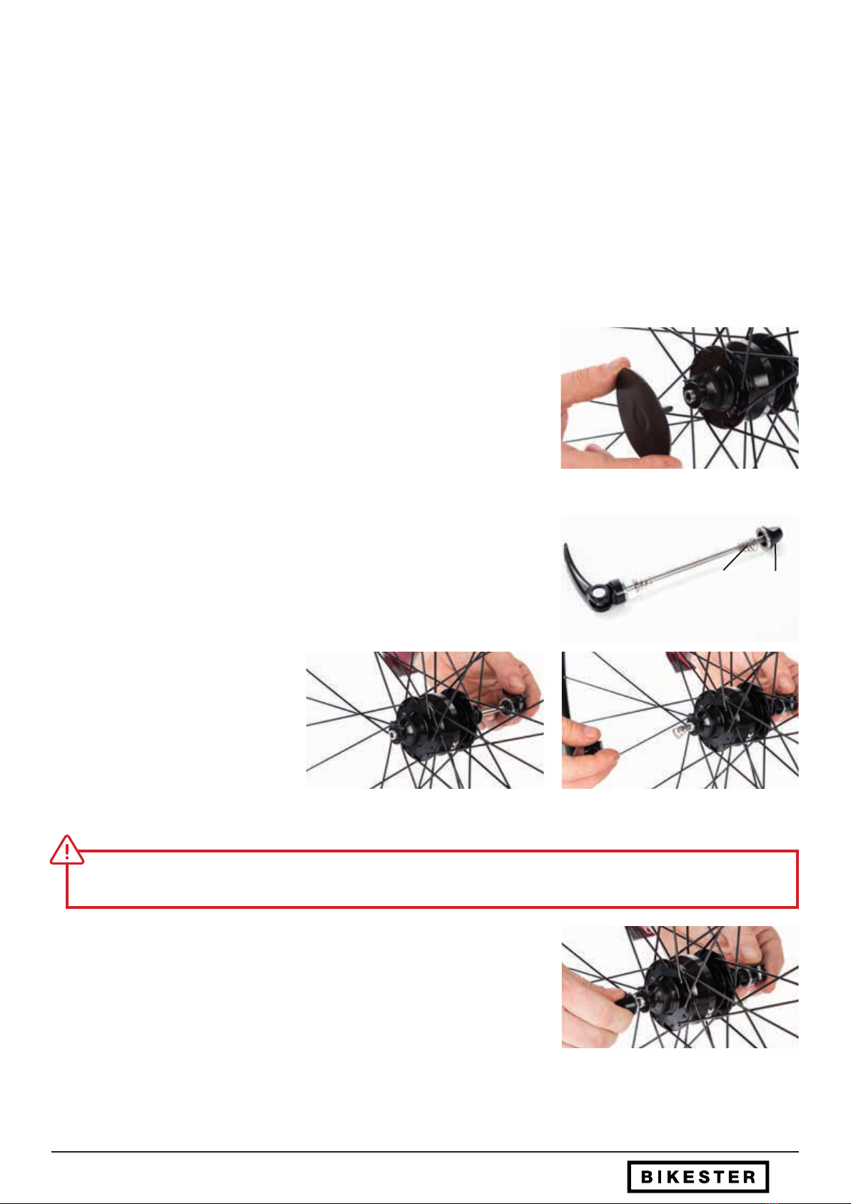
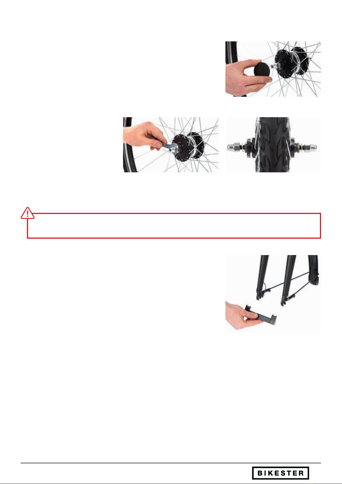
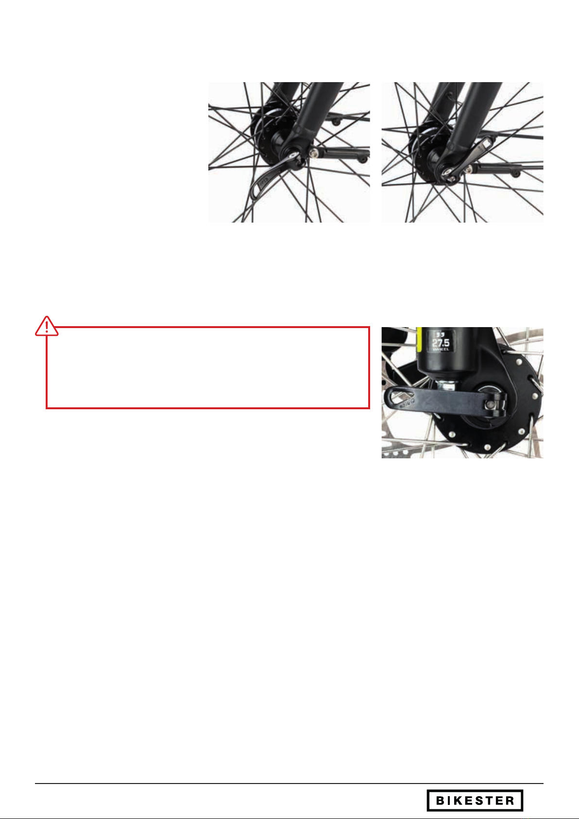
Remove the quick release from the accessory package, loosen the spring clip (A) and
remove the one spiral spring (B). (g. 2)
a) Quick-release front wheel & quick release:
Remove the protective plastic cover on the right and left of the hub at the centre of
the front wheel. (g. 1)
Insert the quick release through the axle
of the front wheel. (g. 3)
Put the spiral spring back on the quick
release. (g. 4)
The thin end of the spiral spring should always point towards the center of the hub.
g. 5
Screw the clamping nut on slightly (g. 5)
The front wheel is now properly prepared.
6
g. 6
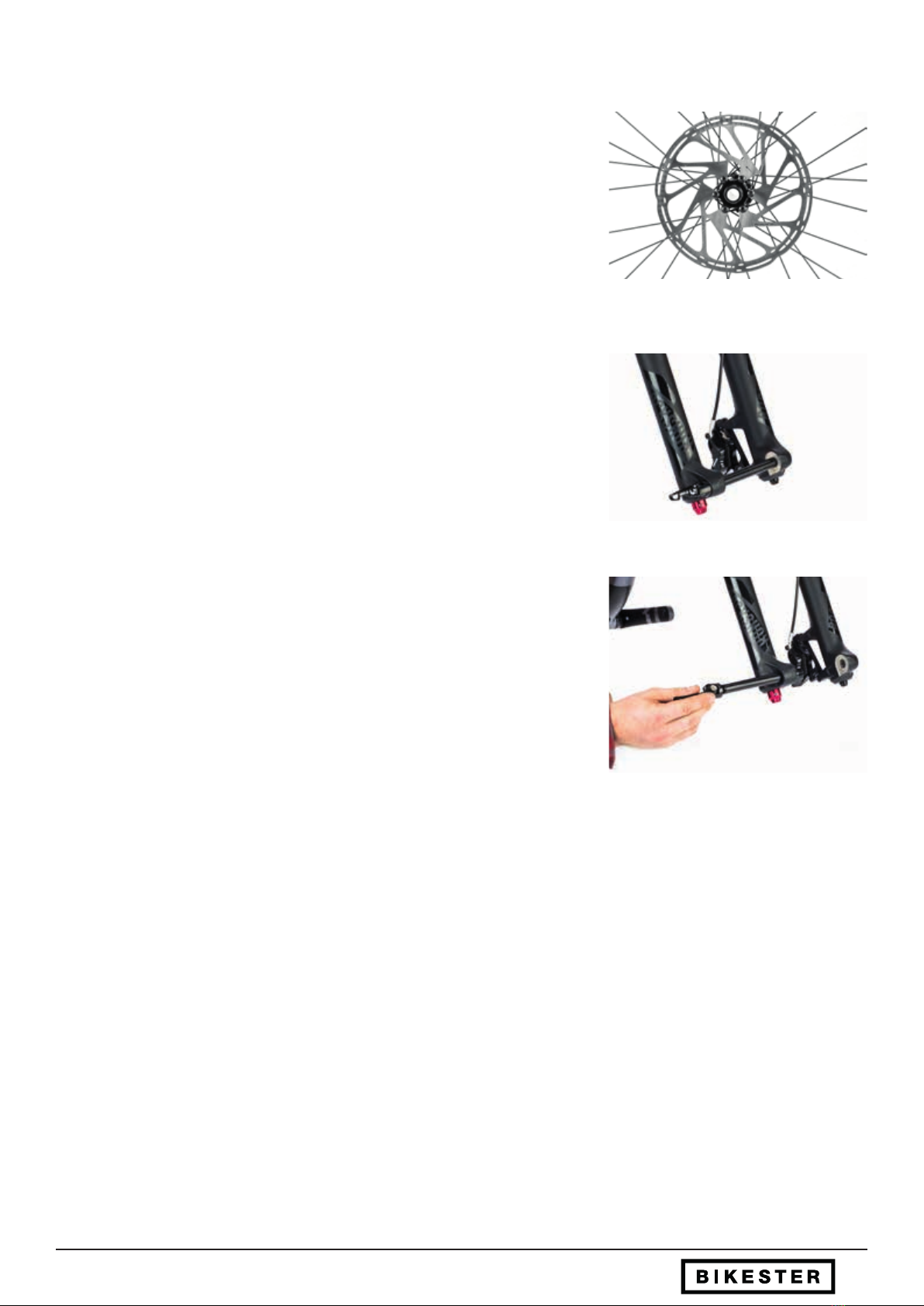
For front wheels with disc brakes (left), the quick release lever should be placed
on the right side. Please do not touch the disc brake rotor, as it may become
contaminated with oil or grease and this could lead to compromised braking
performance. (g. 6)
Front Wheel Assembly - Quick release
g. 7
g. 8
g. 9
In the case of front wheels with rim brakes, the quick release lever can typically be
found on the left side. (g. 7) For bicycles with a hub dynamo, the hub connector must
always be on the right side in the direction of travel.
On wheels without a brake disc, the running direction of the tyre will be printed on the
tyre sidewall. This will help you determine the left and right sides of the wheel.(g. 8)
To prepare the fork, remove the transport safety device from the fork end. (g. 9) In the
conventional quick-release system, the transport safety device only protects the fork
when the front wheel is removed. It is not required to mount the wheel.
7
g. 1
g. 2 g. 3
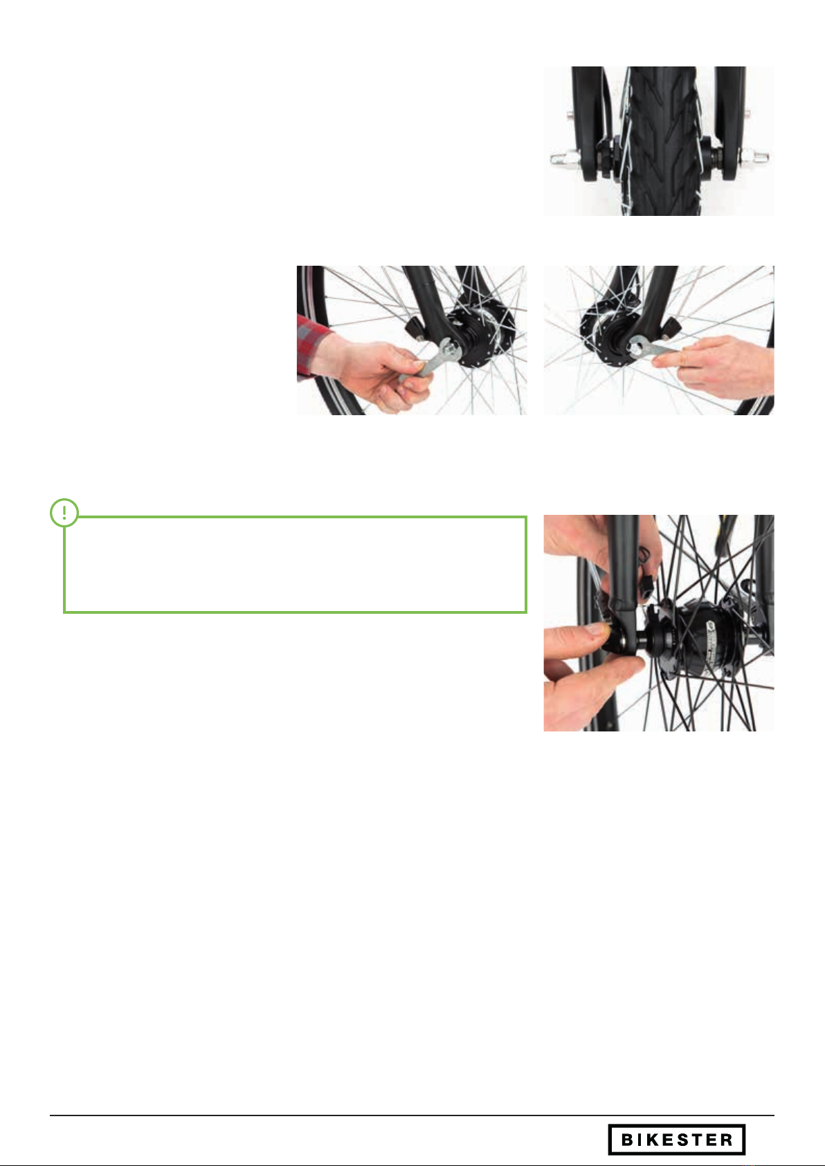
b) Front wheel screw axle with axle nuts
Remove the two plastic protective covers on the left and right of the hub, in the cen-
tre of the front wheel. (g. 1)
Under the cover, the hub axle is now
visible. You will see the hub axle without
a hole, with an external thread, as well as
an axle nut and a washer on each side.
Loosen the two axle nuts on the hub
axle using a 15 mm open-end spanner
until there is a 5-10 mm gap between
the hub and the nut. (g. 2-3)
Please ensure that a washer is installed on each side.
g. 4
In order to prepare the fork, the transport safety device should then be removed
from the fork end. In the conventional screw axle system, the transport safety device
only protects the fork when the front wheel is removed. It is not required to mount
the wheel. (g. 4)
Front Wheel Assembly - Screw axle with axle nuts
8
g. 1
c) Front wheel for thru-axle
Remove the two plastic protective covers on the right and left of the hub, in the cen-
tre of the front wheel. A hollow axis with 12, 15 or 20 mm internal diameter is now
visible. (g. 1)
This is where the mounting axis is mounted in the next step.
g. 2
g. 3
The fork should then be prepared for the installation of the front wheel. For fork and
front wheel for pin-axle mounting (12, 15 or 20 mm diameter), the axle is mounted in
the fork end for transport. (g. 2)
It must now be completely unscrewed and put aside ready for use for the subse-
quent assembly. (g. 3)
Front Wheel Assembly - Thru-axle
9
g. 1
g. 2
g. 3
C
D
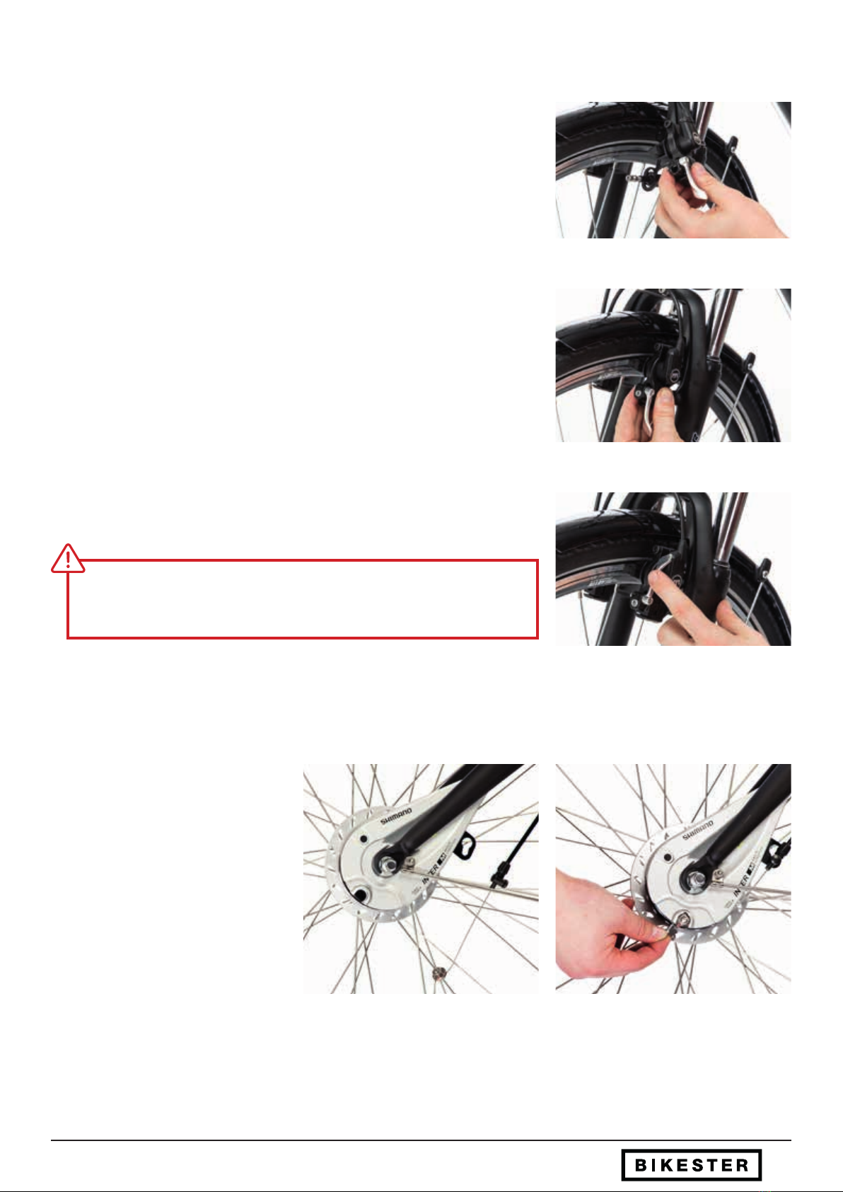
2.2 Preparing the brake
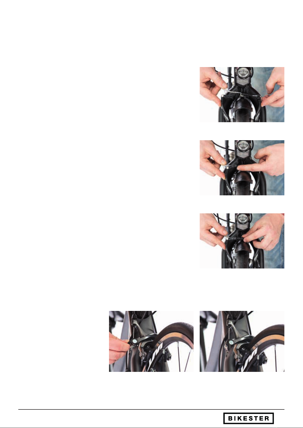
a) Rim brake: V brake - Disconnecting the brake
On bikes with V-brakes, the brake must be suspended for mounting the front wheel.
This is the only way to t the assembled and air-lled tyre through the brake system.
No screw must be loosened.
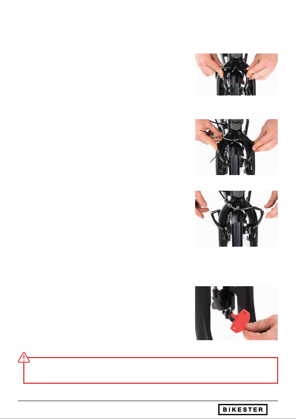
Press both brake arms together by hand to release the brake cable. (g. 1)
Suspend the brake cable by removing the metal tube (C) from the metal rail (D) of the
right brake arm in the direction of travel. (g. 2)
The brake is now suspended and will allow the front wheel to be tted with an
air-lled tyre. (g.3)
g. 4
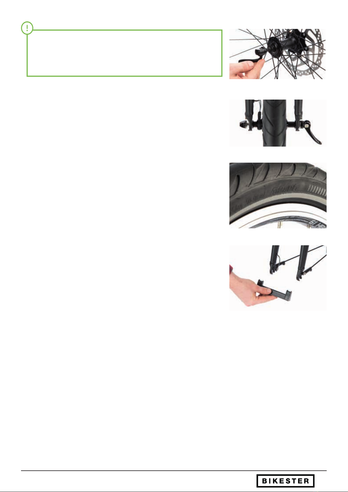
If the transport safety device has been removed, the front bake should not be operated before the front wheel is tted with the
disc brake.
b) Disc brake – Removing the transport safety device
In the case of bikes with hydraulic or mechanical disc brakes, a transport safety de-
vice is installed between the brake linings on the brake calliper. This must be pulled
out before installing the front wheel. (g. 4)
Front Wheel Assembly - Preparing the brake
10
c) Rim brake: Road bike brake – Opening the brake
In the case of bikes with road bike bra-
kes, the brake cable must be released to
mount the front wheel. This is the only
way to t the assembled and air-lled
tyre through the brake system. No screw
must be loosened.
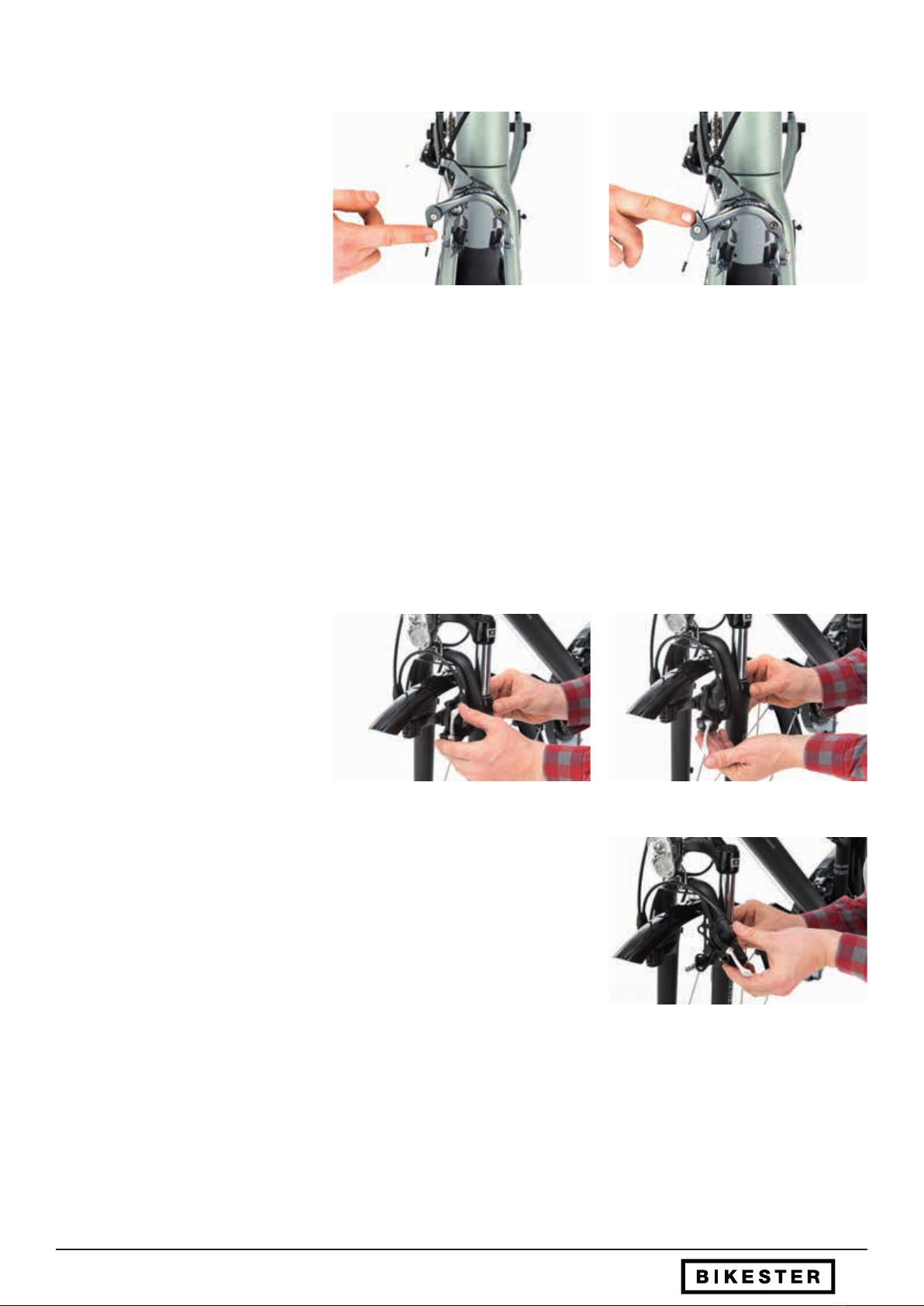
A lever is located on the lower brake arm
for tool-free relaxation and tensioning
of the brake cable. This must be moved
from the closed position (bottom) to the
open position (top). (g. 1-2)
g. 2g. 1
The brake is now suspended and will allow the front wheel to be tted with an air-lled tyre.
d) Rim brake: Hydraulic Magura
On bikes with hydraulic rim brakes, the brake must be unhooked to mount the front wheel. This is the only way to t the assem-
bled and air-lled tyre through the brake system. This does not require the loosening of any screws.
On the left brake body there is a tool-free
quick release fastener. Open the quick
release fastener labelled „Close“ by tilting
the lever downwards. (g. 3-4)
g. 4g. 3
g. 5
Pull the entire left brake body from the brake base of the fork. Be careful not to bend
or damage the hydraulic brake cable. (g. 5)
The hydraulic rim brake is now suspended and allows the front wheel to be
tted with an air-lled tyre.
e) Roller brake
As with the disc brake, there is no need to unhitch the roller brake when installing the front wheel. The brake cable is already
suspended. A transport safety device must not be considered.
Front Wheel Assembly - Preparing the brake
11
Check in which direction the front wheel must be installed. Lift the bike (without the
front wheel) with one hand on the stem. Position the front wheel as straight as possi-
ble from the bottom into the fork. (g. 1)
g. 3
g. 2
Check that the ends of the fork are fully supported on the front axle on both
sides. (g. 2)
In the case of disc brakes, the brake disc must be guided in the centre between
the brake pads without force. (g. 3)
For rim brakes, the front wheel brake must be reinserted (see section 2.5). The
brake is not functional when suspended.
g. 1
Front Wheel Assembly - Installing the front wheel
2.3 Installing the front wheel
12
2.4 Fitting the front wheel
g. 1 g. 2
The quick release lever must be turned completely. The resistance of the closing movement of the quick release lever must in-
crease signicantly after approximately half of the lever travel. Otherwise the preload must be adjusted using the clamping nut on
the opposite side.
a) Quick release
Hand-screw the clamping nut on the
quick release clamp against the lever
until the open quick release tensioner
has approx. 1-2 mm play. Move the quick
release lever round 180°. (From position
"Open“ to position "Close") (g. 1-2)
g. 3
If the quick clamp has been closed correctly, the word "Close“ can now be
read on the outside.(g. 3)
Front Wheel Assembly - Fitting the front wheel - Quick release
13
g. 1
g. 2 g. 3
b) Screw axle
When the front wheel is in position, make sure that the washers are located on both
sides between the fork end and the axle nut. (g. 1) Turn the axle nuts on both sides
by hand.
Use the 15mm wrench to screw the
axle nuts, alternating between right
and left, until they are evenly and rmly
xed. This prevents slipping of the front
wheel. (g. 2-3)
g. 4
If your bicycle has a hub dynamo, then plug the lighting connector on the right
side of the fork to the hub dynamo slot of the front wheel. (g. 4)
Front Wheel Assembly - Fitting the front wheel - Quick release

14
g. 1
c) Thru-axle
When the front wheel is in the correct position, insert the thru-axle through the fork
end without the threaded insert and the hub. (g. 1)
Screw the leverless end of the thru-axle into the threaded insert of the fork. (g. 2)
g. 2
Screw the thru-axle rmly until the front
wheel and axle are free of any play and
the lever can be completely closed with
slight pressure. (g. 3-4)
g. 3 g. 4
Thru-axles are designed to prevent slipping of the front wheel and require slightly lower closing forces than conventional quick
releases or screw axles. If the axle does not have a hinged lever, it should be tightened with medium hand force.
Front Wheel Assembly - Fitting the front wheel - Thru-axle
15
2.5 Fitting the brakes
g. 1
g. 2
For bicycles with disc brakes on their front wheel, no further assembly steps are necessary. For bicycles with rim brakes on the
front wheel, the front wheel brake must be mounted again after assembly. Depending on your type of brake, proceed as follows:
V-Brake
Press the brake arms of the v-brake together with one hand until the brake pads lie
at on the rim. (g. 1)
Using the other hand, pull the metal tube of the brake cable in the direction of the
support (metal rail) with the other hand so that the end of the guide tube can be
attached. (g. 2)
g. 3
Slip the rubber sleeve over the end of the guide tube. (g. 3)
Front Wheel Assembly - Fitting the brakes
Side pull caliper (road bike brake)
After installing the front wheel, close the
lever on the lower brake arm by moving
it from the upper position to the lower
position. (g. 4-5)
g. 4 g. 5
16
Rim brake - Hydraulic Magura
Position the left brake body on the brake mount of the fork. (g. 1)
Adjust the height of the brake body so that the brake pad sits exactly at the height
of the rim ank. (g. 2)
Close the quick release lever on the brake body, so that the label "Close“ can be
read. (g. 3)
g. 1
g. 2
g. 3
Please note the operating instructions of the brake manufacturer Magura.
Roller brake
To mount the preset roller brake, the ca-
ble retaining screw must rst be moun-
ted in the lower position.
Press the connector towards the upper
brake arm to reduce the cable tension.
Push the cable sheath holder into the
guide slot of the brake arm and engage it
in the intended position. (g. 4-5)
g. 4 g. 5
Front Wheel Assembly - Fitting the brakes
17
2.6 Function check
g. 1
g. 2
Check the free-running of the front wheel. If the front wheel
is visibly slanted, running unevenly or signicantly grinds the
brake, the front wheel has not been installed correctly! (g. 1)
Check the function of the front brake. You should be able to
easily stop the freely rotating front wheel with the front brake –
without having to pull the brake lever as far back as the handle.
(g. 2)
Front Wheel Assembly - Function check
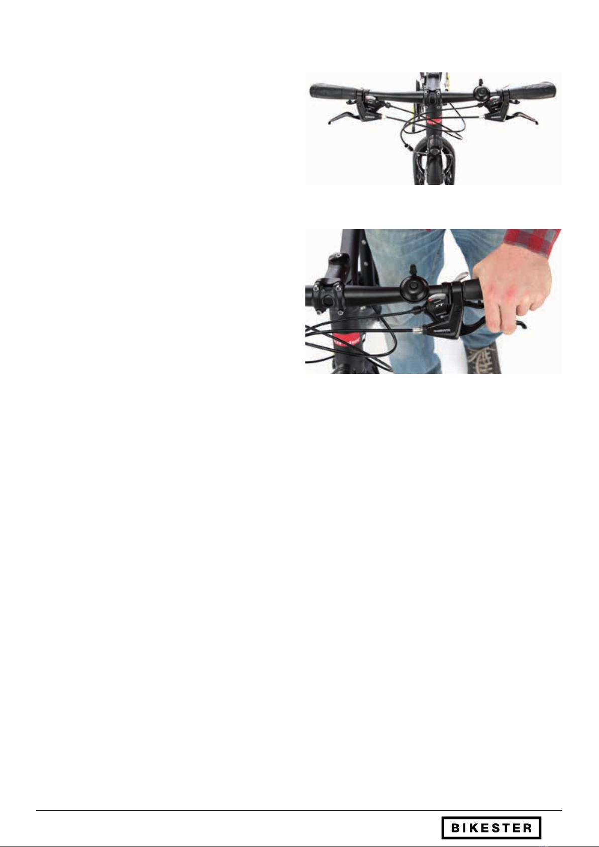
18
3. Adjustment of handlebar/stem
The pre-assembled handlebar was turned to the side for transportation. With a few, simple hand movements you can bring the
stem and handlebars into the correct riding position.
On most bicycles, the stem is rotated with the handlebars already mounted. You just have to loosen a few screws and tighten
them again to bring your handlebars (and all functioning shifters and brake levers) into the correct position.
These steps dier according to the design of your handlebars and stem. Choose the appropriate method for your bike
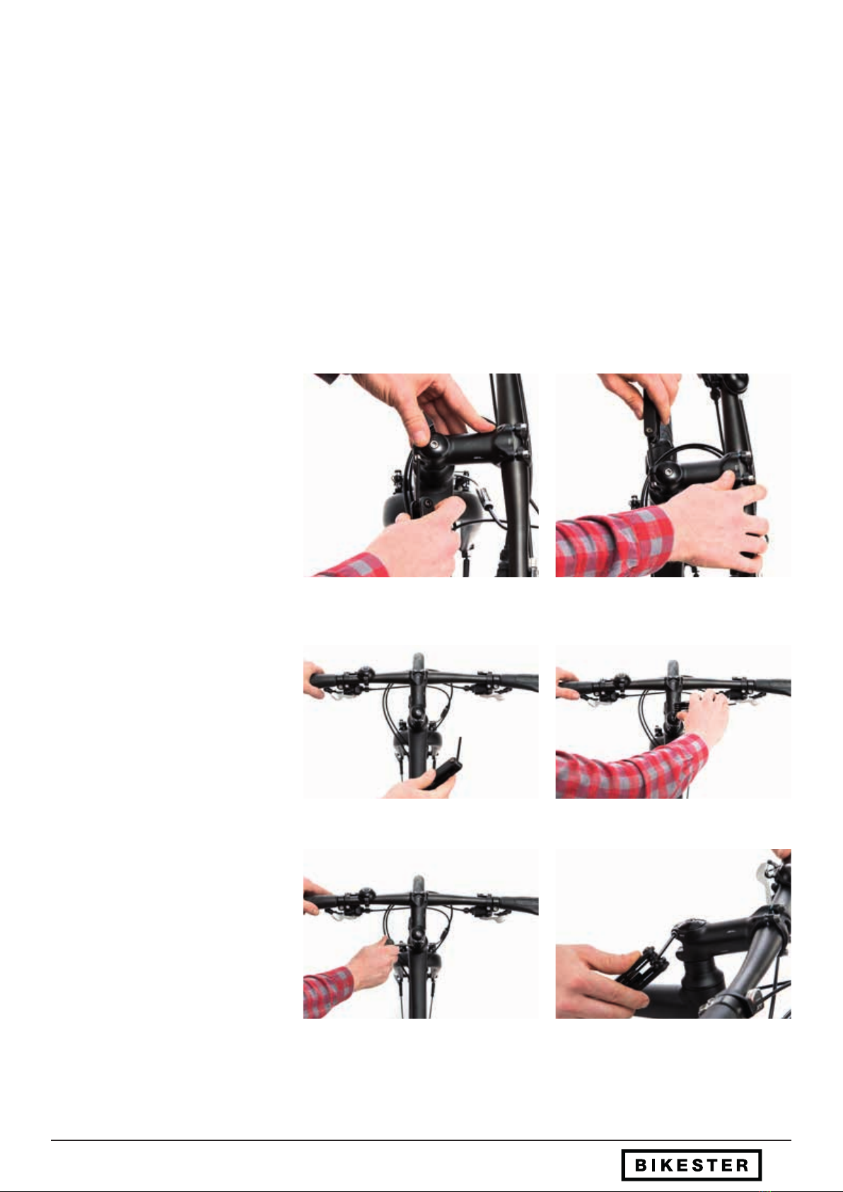
3.1 Ahead control bearing & assembly
Many modern bicycle models use the so-called Ahead system for fork, steering bearing and stem. The stem is clamped with two
outer screws on the continuous fork steerer and the headset bearing is adjusted with a screw from above.
g. 3
g. 1 g. 2
Loosen the screw connection between
the stem and the fork steerer until the
stem can be rotated. (g. 1-2)
Align the stem in a straight line with the
front wheel. (g. 3) Re-adjust the be-
aring clearance of the headset. For this,
please tighten the Aheadset star nut bolt
a quarter-turn and check whether the
bearing has clearance. (g. 4)
g. 4
Carefully repeat step by step until you
detect no more play and the handlebars
can still be rotated smoothly and easily:
Now tighten the screw connection of the
stem / fork shaft with the appropriate
Allen key on the minitool. (g. 5-6)
g. 5 g. 6
Adjustment of handlebar/stem - Ahead control bearing & assembly
19Adjustment of handlebar/stem - Quill stem & threaded headset
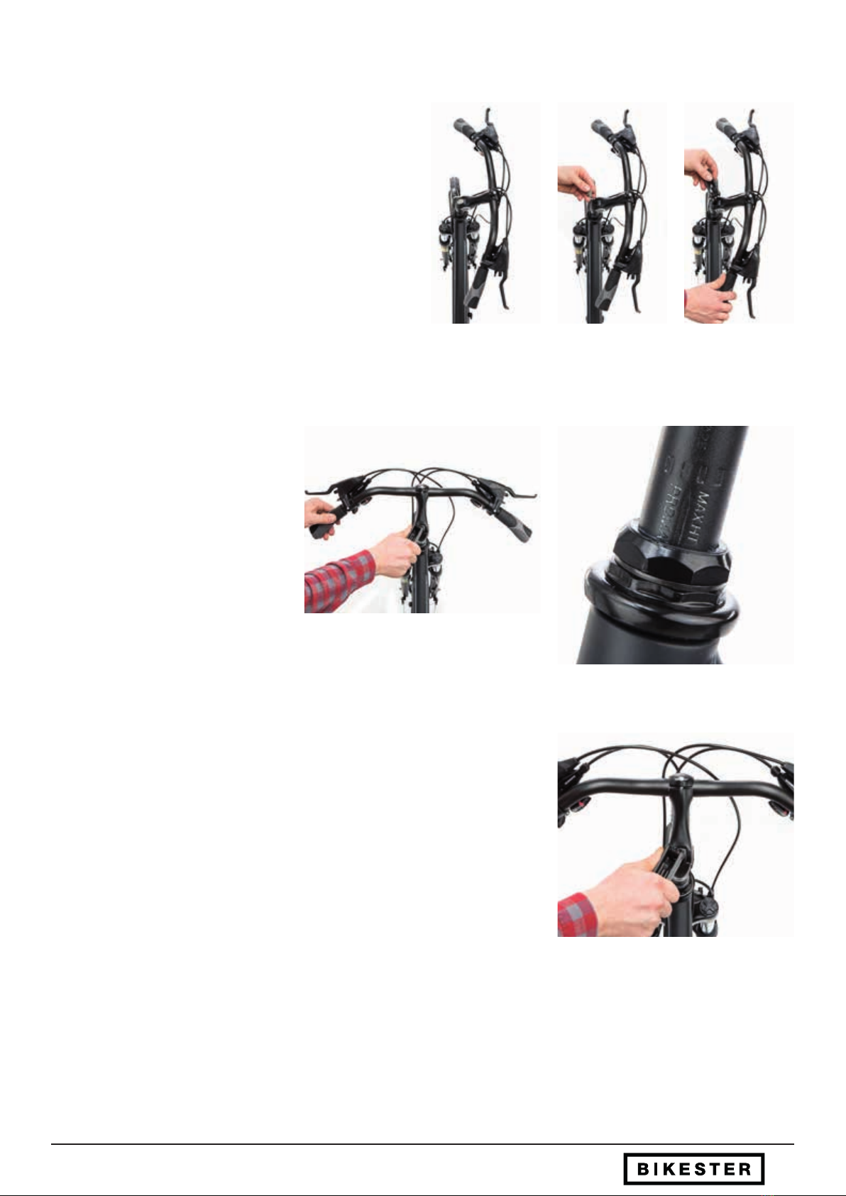
3.2 Quill stem & threaded headset
Today‘s classic combination of quill stem and threaded headset
are still common on everyday bicycles since they allow good
adjustability of the handlebar height without additional compo-
nents. In this system, the headset with bearing is screwed onto
the threaded fork steerer independently of the stem. The quill
stem has a clamping cone which is inserted into the steerer
tube and rmly xed from above with a screw.
Loosen the screw on the head of the stem by about two turns.
(g. 1-3)
The stem should now be rotatable in the fork and exible in
height.
g. 1 g. 2 g. 3
The stem can now be positioned so that
it is exactly straight on to the direction of
travel. (g. 4)
Also the height of the unit of stem and
handlebar can be adjusted now.
Please make sure that the stem is not
positioned above the limit mark on the
stem. (g. 5)
The screw on the head can now be tightened again with the attached tool. (g. 6)
g. 4
g. 6
g. 5
20
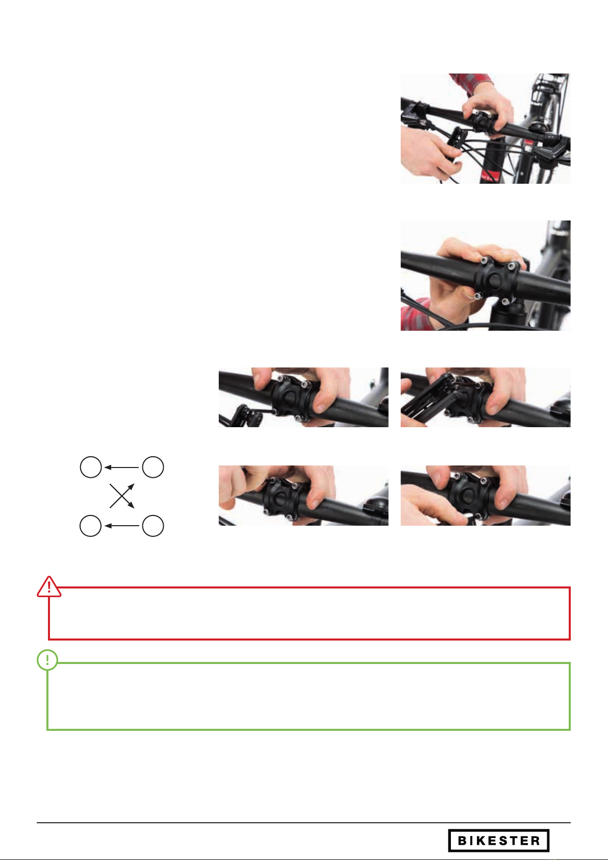
3.3 Place the handlebars in position
g. 1
g. 2
Loosen the screws at the handlebar / stem connection slightly. (g.1)
Turn the handlebars to a comfortable position for you. Make sure that the handlebar
remains positioned centrally in the stem. (g. 2)
Tighten the handlebars evenly with the
appropriate Allen key on your minitool by
alternately tightening the pre-fastening
bolts. (g. 3-6)
g. 3
g. 5
g. 4
g. 6
Ensure uniform tightening torque for all pre-clamp bolts! The clearance of the stem clamp must be identical; otherwise there is
a risk of a serious material defect!
High clamping forces are not suitable here. The lever of the small minitool and medium hand forces are sucient. It is best to
use a suitable torque wrench and pay close attention to the Newton meter indication for the handlebar clamp bolts of the stem
manufacturer.
Adjustment of handlebar/stem - Place the handlebars in position
3 2
41
Table of contents


