Bilanciai DD1010 User manual
WEIGHING INDICATOR
DD1010 FLYNET
USE, MAINTENANCE AND INSTALLATION MANUAL
Edition 17/12/2019
Manual code 81320560


1
DD1010 FLYNET
CONTENTS
1INTRODUCTION............................................................................................................................4
1.1 Foreword............................................................................................................................................4
1.2 Documentation...................................................................................................................................5
1.3 Symbols.............................................................................................................................................5
1.4 Glossary of terms used......................................................................................................................6
1.5 Description of the indicator ................................................................................................................8
1.6 Key ....................................................................................................................................................8
1.7 Technical characteristics of the indicator...........................................................................................9
1.8 Declaration of conformity.................................................................................................................10
1.9 Indicator overall dimensions and weight..........................................................................................10
1.9.1 Plastic version ...................................................................................................................10
1.9.2 Tabletop stainless steel version ........................................................................................11
1.9.3 Wall-mounted stainless steel version ................................................................................11
1.10 Instructions for disposal of electrical or electronic waste .................................................................12
1.11 Instructions for technical service request.........................................................................................12
1.12 Warranty..........................................................................................................................................13
1.13 Spare parts......................................................................................................................................14
2SAFETY REQUIREMENTS.........................................................................................................16
2.1 Not allowed uses .............................................................................................................................16
2.2 Regulations......................................................................................................................................16
2.3 Conditions of use.............................................................................................................................16
3DELIVERY AND INSTALLATION...............................................................................................17
3.1 Installation........................................................................................................................................19
3.1.1 Tabletop installation...........................................................................................................19
3.2 Connecting the indicator to the mains..............................................................................................19
3.2.1 Checks ..............................................................................................................................19
3.2.2 Wiring diagram (version with connectors)..........................................................................20
3.2.3 Wiring diagram (version with cable glands).......................................................................21
3.3 Connecting the indicator to the weighing platform ...........................................................................23
3.3.1 Wiring diagram (with platform)...........................................................................................24
3.3.2 Equipotential between indicator and weighing platform.....................................................24
3.3.3 Digital Scale serial connection...........................................................................................25
3.3.4 Analogue Scale serial connection......................................................................................25
3.4 Serial connections ...........................................................................................................................26
3.4.1 COM4 serial connection....................................................................................................26
3.4.2 COM6/7 serial connection.................................................................................................26
3.4.3 RS232 connections ...........................................................................................................27
3.4.4 RS422 connections ...........................................................................................................27
4CONTROLS, SWITCHING ON AND OFF...................................................................................28
4.1 On/Off key........................................................................................................................................28
4.2 Touch screen...................................................................................................................................30
4.3 External keyboard and mouse.........................................................................................................30
5USING THE INDICATOR ............................................................................................................31
5.1 Indicator configuration .....................................................................................................................31
5.1.1 Application.........................................................................................................................31
5.2 System.............................................................................................................................................32
5.2.1 Metrology Management.....................................................................................................32
5.2.2 Serial Ports........................................................................................................................55
5.2.3 Printers/Readers/IOs.........................................................................................................55
5.2.4 Log Management and System Errors................................................................................60
5.2.5 Access levels.....................................................................................................................61
5.2.6 Buzzer...............................................................................................................................62
5.2.7 Date and time....................................................................................................................62
5.2.8 Email .................................................................................................................................64
5.3 Cards...............................................................................................................................................65
5.4 PDF and network printer..................................................................................................................66
5.4.1 Network printer..................................................................................................................66

2
DD1010 FLYNET
5.4.2 PDF...................................................................................................................................68
5.5 Transmission ...................................................................................................................................70
5.5.1 Mpp ...................................................................................................................................70
5.5.2 Network .............................................................................................................................72
5.5.3 Serial.................................................................................................................................73
5.5.4 Indicator parameters..........................................................................................................74
5.5.5 Field bus............................................................................................................................75
5.5.6 Printed data string .............................................................................................................76
5.5.7 Analogue output ................................................................................................................78
5.6 Activating the optional services........................................................................................................79
5.7 Themes............................................................................................................................................79
5.8 Shortcut keys...................................................................................................................................80
5.9 Switching off ....................................................................................................................................80
5.10 Access levels...................................................................................................................................80
5.11 Error management...........................................................................................................................81
5.12 Sharing data ....................................................................................................................................81
5.12.1 Database...........................................................................................................................82
5.13 Adding an external printer................................................................................................................83
5.14 Adding a reader...............................................................................................................................84
5.15 Adding a network or PDF printer......................................................................................................85
5.16 Testing a serial transmission ...........................................................................................................86
6OPTIONS.....................................................................................................................................87
6.1 Installing Optional Cards..................................................................................................................87
6.2 Optional Card Overview...................................................................................................................88
6.2.1 Sound card........................................................................................................................88
6.2.2 8 in/12 out card..................................................................................................................89
6.2.3 Pulse input analogue output card......................................................................................92
7ERROR MESSAGES...................................................................................................................93
7.1 Indicator errors.................................................................................................................................93
7.2 Scale Errors.....................................................................................................................................93
8PARAMETER CUSTOMISATION...............................................................................................95
9ACCESS TO METROLOGICAL PARAMETERS .......................................................................96
9.1 Version with connectors...................................................................................................................96
9.2 Version with cable glands................................................................................................................97
9.3 Internal scale sampling....................................................................................................................99
10 DISASSEMBLING COMPONENTS..........................................................................................100
10.1 Disassembling support (only for stainless steel version) ...............................................................100
10.2 Opening the indicator.....................................................................................................................101
10.2.1 Plastic version .................................................................................................................101
10.2.2 Stainless steel version.....................................................................................................102
10.3 Disassembling front panel and display ..........................................................................................103
10.3.1 Plastic version .................................................................................................................103
10.3.2 Stainless steel version.....................................................................................................105
10.4 Disassembling the indicator power supply unit..............................................................................107
10.4.1 Stainless steel version with cable glands ........................................................................107
10.5 Disassembling power supply unit for scale....................................................................................108
10.5.1 Plastic version .................................................................................................................108
10.5.2 Stainless steel version.....................................................................................................109
10.6 Disassembling lithium battery........................................................................................................110
10.6.1 Plastic version .................................................................................................................110
10.6.2 Stainless steel version with connectors...........................................................................111
10.6.3 Stainless steel version with cable glands ........................................................................112
10.7 Disassembling weighing cell unit and indicator power supply unit (stainless steel version with cable
glands only) ...................................................................................................................................113
10.8 Disassembling CPU module..........................................................................................................114
10.8.1 Plastic version .................................................................................................................114
10.8.2 Stainless steel version with connectors/cable glands......................................................115
10.9 Disassembling digital scale input...................................................................................................116
10.9.1 Plastic version .................................................................................................................116

3
DD1010 FLYNET
10.9.2 Stainless steel version with connectors...........................................................................117
10.9.3 Stainless steel version with cable glands ........................................................................118
10.10 Disassembling analogue scale input..............................................................................................119
10.10.1 Plastic version .................................................................................................................119
10.10.2 Stainless steel version with connectors...........................................................................120
10.10.3 Stainless steel version with cable glands ........................................................................121
10.11 Disassembling serial expansion card.............................................................................................122
10.11.1 Plastic version .................................................................................................................122
10.11.2 Stainless steel version with connectors...........................................................................123
10.11.3 Stainless steel version with cable glands ........................................................................124
10.12 Disassembling HDMI port..............................................................................................................125
10.12.1 Plastic version .................................................................................................................125
10.12.2 Stainless steel version with connectors...........................................................................126
10.13 Disassembling motherboard..........................................................................................................127
10.13.1 Plastic version .................................................................................................................127
10.13.2 Stainless steel version with connectors...........................................................................128
10.13.3 Stainless steel version with cable glands ........................................................................129
10.14 Connecting peripheral devices to serial and USB ports.................................................................129

4
DD1010 FLYNET
1 INTRODUCTION
1.1 Foreword
The purpose of this manual is to inform the operator on the basic requirements and criteria for
installation, correct and safe use of the weighing equipment and execution of a systematic
maintenance through texts and figures
Always keep this manual easily accessible! Always follow the instructions given!
The safe operation of the equipment is entrusted to the operator, who should have detailed
knowledge of it.
It is the responsibility of the user to make sure that the installation complies with the current
applicable provisions.
The equipment must only be installed by specialised personnel who must have read and
understood this manual.
“Specialised personnel” means personnel who, as a result of training and professional
experience, have been expressly authorised by the “Equipment Safety Manager” to install, use
and maintain the equipment.
For any anomaly detected, please contact your nearest Service Centre.
Any attempt to disassemble, modify or tamper with the equipment by the user or unauthorised
personnel is forbidden; in this case, the warranty is immediately void and the Manufacturer is not
liable for any damage caused to persons or property.
It is also forbidden to alter or delete the data on nameplates, closing and legalisation stamps of
the indicator; therefore, make sure that all the plates are present and readable and, if not,
contact the After Sales Service.
The Manufacturer is not liable for any damage resulting from careless handling of the indicator.
The information and illustrations below are updated to the date of issue shown on the first page
of the manual.
The Manufacturer is committed to the continuous optimisation of its products with possible
modifications to parts or components of the purchased equipment or parts of the software.
All technical information contained in this manual are the exclusive property of the Manufacturer
and must be considered confidential.
Reproduction and dissemination, even partial, of this manual on paper, IT support and WEB
without the written authorisation of the Manufacturer is forbidden.
It is also forbidden to use this manual for purposes other than those strictly related to the
installation, use and maintenance of the indicator.
In order to detail some aspects of the equipment with greater effectiveness and clarity, some
illustrations may represent the equipment without guards. It is strictly forbidden to use the
equipment without guards.

5
DD1010 FLYNET
1.2 Documentation
The standard documentation supplied with the DD1010 FLYNET indicator consists of:
QUICK START
This is a multilingual document, printed on paper, which contains brief instructions for immediate
use, as well as the declaration of conformity and the main danger warnings.
USE, MAINTENANCE AND INSTALLATION MANUAL
Multilingual, PDF file, available in printed version on request.
APPLICATION MANUAL AND PARAMETERS
Multilingual, PDF file available in printed version on request.
Any additional copies of the equipment documentation can be requested from the After Sales
Service of our Sales and Service network.
1.3 Symbols
Below are the symbols used in the manual to draw the attention of the reader to the different levels
of danger in the “Use and Maintenance” operations of the instrument.
DANGER
Information or procedure which, if not carefully performed, results in death or serious personal
injury.
ATTENTION
Information or procedure which, if not carefully performed, may result in minor personal injury or
damage to the instrument.
WARNING
Information or procedure to advise the operator on the optimal use of the equipment for a longer
life, avoid damage or loss of programming, optimise the work in compliance with metric
standards.
TECHNICAL SERVICE
The sections showing the following pictogram on the side are the exclusive competence of the
qualified technician made available by the manufacturer to carry out complex operations in
particular situations. The skills are mechanical and/or electrical and/or electronic and/or software,
depending as the case may be.
ATTENTION
IT IS STRICTLY FORBIDDEN TO CARRY OUT SUCH OPERATIONS WITHOUT THE
APPROPRIATE AND ADEQUATE AUTHORISATION AS WELL AS SPECIFIC TRAINING!
RISK OF INJURY TO PERSONNEL IN CHARGE OR DAMAGE TO THE PURCHASED
EQUIPMENT!

6
DD1010 FLYNET
1.4 Glossary of terms used
The manual uses technical terminology or terminology with different meaning from the common one.
The terms and abbreviations that may be used in the documentation provided are explained below.
DANGER: a potential source of injury or damage to health;
DANGEROUS ZONE: any zone inside and/or near the equipment where the presence of an
exposed person poses a risk to the safety and health of that person;
EXPOSED PERSON: Any person who is wholly or partly in a dangerous zone;
RISK: a combination of the probability and severity of an injury or damage to health that may arise in
a hazardous situation;
GUARD: component of the equipment used specifically to ensure protection by means of a physical
barrier;
PROTECTIVE DEVICE: device (other than a guard) that reduces the risk, alone or associated with a
guard;
INTENDED USE: the use of the equipment in accordance with the information provided in the
instructions for use;
MISUSE: use the equipment in a different way from that indicated in the instructions for use, but
which may result from easily predictable human behaviour;
RESIDUAL DANGER: a danger that could not be eliminated or reduced by design, against which
the protections are not (partially or totally) effective;
WEIGHING INSTRUMENT: a measuring instrument used to determine the mass of a body using the
action of gravity on that body. A weighing instrument can also be used to determine other quantities,
parameters or characteristics related to the mass;
NON-AUTOMATIC WEIGHING INSTRUMENT OR INSTRUMENT: a weighing instrument that
requires the intervention of an operator during weighing;
MEASURING INSTRUMENT: any device or equipment or system (the term may be used as a
synonym in this manual) with measurement functions as defined by the MID Directive (2014/32/EU).
LEGAL METROLOGICAL CONTROLS: controls for reasons of public interest, public health, public
safety, public order, protection of the environment, levying of taxes and duties and fair trading,
intended to verify that a measuring instrument is capable of performing its intended function.
AUTOMATIC WEIGHING INSTRUMENTS: Automatic weighing instruments defined below, whose
purpose is to determine the mass of a body using the action of gravity acting on that body.
AUTOMATIC WEIGHING INSTRUMENT: An instrument which determines the mass of a product
without the intervention of an operator and which follows a predefined programme of automatic
processes characteristic of this instrument.
AUTOMATIC CATCHWEIGHER: An automatic weighing instrument that determines the mass of
pre-assembled discrete loads (for example prepackages) or single loads of loose material.
AUTOMATIC CHECKWEIGHER: Automatic catchweigher that subdivides articles of different mass
into two or more subgroups according to the value of the difference of their mass and a nominal set-
point.
WEIGHT LABELLER: Automatic catchweigher that labels individual articles with the weight value.

7
DD1010 FLYNET
WEIGH/PRICE LABELLER: Automatic catchweigher that labels individual articles with the weight
value, and price information.
O.I.M.L. –International Organization of Legal Metrology OIML RXX requirement
Where XX is used to specify the requirement according to the category of measuring instruments
OIML R76-1 and OIML R76-2: (NAWI) Non-automatic weighing instruments.
PERSONAL PROTECTIVE EQUIPMENT (PPE): Personal protective equipment means any
equipment intended to be worn and/or used by the worker for the purpose of protecting him/her
against one or more risks that could endanger safety or health at work, and any element or
accessory intended for this purpose.
The following is not personal protective equipment:
Ordinary occupational clothing and uniforms not specifically designed to protect the safety and
health of the worker;
The equipment of emergency and rescue services;
Personal protective equipment of armed forces, police forces and service personnel for
maintaining law and order;
Personal protective equipment specific to road transport vehicles;
Sporting materials;
Materials for self-defence or deterrence.
Portable devices to identify and report risks and harmful factors.
USER: The user (businessman/company) is considered to be the person using the equipment for its
intended use or entrusting its use to competent and specifically trained persons.
ADVANCED QUALIFIED TECHNICIAN: This term refers to a technician who has specific skills in
the metrology field (with reference to the provisions of metrology directives 2014/31/EU and
2014/32/EU and related metrology terminology), who can read wiring diagrams and technical
documentation of the equipment and who has good electrical knowledge in order to adjust electrical
parts and electrical systems for maintenance, repair, calibration and replacement. He/she can
operate in the presence of voltage inside control boxes, junction boxes, control equipment etc. only if
he/she is a suitable person (see EN50110-1 and EN 50110-2).
DANGER
It is the responsibility of the purchaser to make sure that he/she has all necessary information
before carrying out the installation, adjustment and operation of the equipment purchased.

8
DD1010 FLYNET
1.5 Description of the indicator
The DD1010 FLYNET indicator allows performing highly accurate and reliable weighing operations.
Designed for industrial applications.
Supplied as standard with metrological weighing management software.
Body in ABS and stainless steel; available both in tabletop and wall mounting version.
Simple and immediate use with the 5.7” touch screen colour display.
Flexible and customizable functions and graphic layout.
Equipped with a powerful relational SQL data base for the management of weighing data.
Advanced connectivity and network communication.
Programming and customisation from PC via network.
1.6 Key
The following manual refers to operations available in different models defined at the time of
purchase. Below is the terminology used in this manual.
PLASTIC VERSION: applies only to the plastic version.
STAINLESS STEEL VERSION WITH CONNECTORS: applies only to the stainless steel version
with connectors.
STAINLESS STEEL VERSION WITH CABLE GLANDS: applies only to the stainless steel version
with cable glands.
STAINLESS STEEL VERSION: applies to the stainless steel version with connectors and cable
glands.
If nothing is specified, it means present in all models.

9
DD1010 FLYNET
1.7 Technical characteristics of the indicator
Power supply
Direct
12 Vdc/3 A (Min 11 V - Max 15 V)
Via network adapter
L+N+R
110 - 240 Vac (-15% ... +10%)
1.8 A
50 - 60 Hz
60W Max
Ground socket
Equipotential for weighbridge
Scales
Total
1/2
(or 1 analogue, or 1 digital, or 2 analogue or 2
digital)
Repeater operation
Analogue scale
Connectable cells
Up to 12 x 350 ohm analogue cells per scale
Minimum impedance
29 ohm per scale
Load cell power supply
4.5-5 Vdc
Internal resolution
1000000 points at 10 Hz
Resolution in type-approved version
1 range of 6000
Maximum input signal
35 mV
Sensitivity
0.6 µV/division
Full scale stability
< 5 ppm/°C
Zero stability
< 5 ppm/°C
Digital scale
Connectable cells
Up to a scale with 16 digital cells or two scales
with 8 digital cells each
Load cell power supply
8 to 15 Vdc
Internal resolution
200000 points @ 25 conv/s
Resolution in type-approved version
1 range of 6000
Environmental characteristics
Compensated temperature range
-10 to + 40 °C
Operating range
-10 to + 40 °C
Maximum humidity
85% @ 40 °C
IP protection rating
Plastic version and stainless steel version with
connectors: direct outputs IP 20 and front IP 65.
Stainless steel version with cable glands IP 69K
User interface
Video
5.7” LED TFT display
Keyboard
Touch screen
10
DD1010 FLYNET
Communication ports
USB Type A
4 (+1 internal)
Serial ports
2 x RS232 (COM4/COM6)
Or
1xRS232 + 1xRS422 (COM4/COM7)
Or
2xRS232 + 1xRS422 (with optional bifid cable)
Ethernet 10/100
1
Expansions
Slots for optional boards
2 + dual serial option
1.8 Declaration of conformity
The declaration of conformity is available in the QUICK START manual to which you can refer for
details.
1.9 Indicator overall dimensions and weight
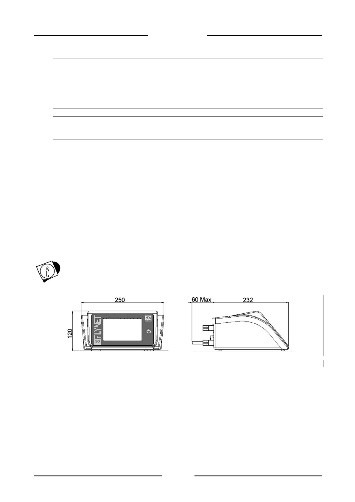
1.9.1 Plastic version
WARNING
The plastic version, whether it is placed on a table or mounted on a wall, is the same. Only the
indicator direction changes.
Figure 1.7-1 - Weighing indicator dimensions, plastic version
Dimensions (in mm): see Figure 1.1.
Weight: 2 kg

11
DD1010 FLYNET
1.9.2 Tabletop stainless steel version
Figure 1.7-2 - Weighing indicator dimensions, tabletop stainless steel version
Dimensions (in mm): see Figure 1.2.
Weight: 5 kg
1.9.3 Wall-mounted stainless steel version
Figure 1.7-3 - Weighing indicator dimensions, wall-mounted stainless steel version
Dimensions (in mm): see Figure 1.3.
Weight: 5 kg

12
DD1010 FLYNET
1.10 Instructions for disposal of electrical or electronic waste
This symbol on the weighing instrument purchased indicates that:
This electrical or electronic equipment cannot be disposed of as solid
urban waste.
Separate collection is required.
It can be returned to the distributor when purchasing new equipment.
Improper use or disposal of such equipment may cause pollution to the
environment or endanger human health.
Failure to comply with the above indications is subject to sanctions
according to the regulations in force.
In particular:
Outer casing and mechanical components are made of plastic and/or metallic materials.
The casing contains printed circuit boards with electronic components.
The electrical connections are made with insulated copper conductors.
ATTENTION
Dispose of this equipment via separate waste collection either handing it over to the distributor or
to separate waste collection centres.
1.11 Instructions for technical service request
Any request for information or service intervention at the customer’s premises or clarification
regarding the technical aspects of the equipment or of this document must be addressed to:
In case of malfunctions or faults for which the intervention of specialised technicians is required,
please contact the nearest service centre (http://www.coopbilanciai.it/it/home/rete-vendita-e-
assistenza by selecting your country) or directly the manufacturer.
In particular, the customer must provide the manufacturer with the following data:
type of equipment - model, identification number, year of manufacture;
serial number of the instrument available on the stamped label;
characteristics of the system on which the equipment is installed;
maximum capacity "Max=" and metrology division "e="
shortcomings detected
SOCIETÀ COOPERATIVA BILANCIAI
Headquarters and factory:
Via S.Ferrari, 16
41011 CAMPOGALLIANO (MO) ITALY
Tel. +39 059/893611 - Fax. +39 059/527079
www.coopbilanciai.it
info@coopbilanciai.it

13
DD1010 FLYNET
exact address of the site/factory where the equipment is installed
contact person.
1.12 Warranty
In the construction of the equipment/indicator, the manufacturer has used materials whose type and
quality are considered to be suitable in its unquestionable judgement.
Even after commissioning, the manufacturer may make modifications considered to be an
improvement in its unquestionable judgement.
The manufacturer guarantees the equipment as free from defects in material or workmanship for the
period specified in the contract with the purchaser/customer.
During this period, the manufacturer undertakes to eliminate the evident defects and/or shortcomings
detected by the buyer/customer within the necessary time. Defective components, excluding parts
subject to wear, will be replaced free of charge during the warranty period, without prejudice to travel
and shipping expenses.
Finally, transport, inspection, disassembly and reassembly costs due to the intervention of a
manufacturer technician or its delegate are excluded from the warranty if the defects and/or
shortcomings detected are not covered by this warranty.
This warranty is only applied to the purchaser in compliance with the contractual rules, and if the
installation and use of the equipment is carried out by the purchaser in accordance with the
instructions contained in this manual.
The manufacturer will not be liable for faults or malfunctions if maintenance deficiencies, lack of
cleaning, replacement with non-original or unauthorised parts and use of the equipment in a manner
different from that indicated in this instruction manual are found. Furthermore, this warranty does not
cover any parts replaced or repaired and all parts that are subject to wear due to their specific use.
Any further obligation and/or compensation and/or indemnity by the manufacturer is expressly
excluded.
The warranty excludes any and all liability for direct or indirect damage to persons and property
resulting from incorrect or incomplete installation, incorrect use and inadequate maintenance of the
equipment. Partial or total non-compliance with the legal requirements in force in the country of use.
The warranty excludes any and all liability for damage due to lack of production or incorrect
metrological evaluation.
Returns of goods will not be accepted unless authorised by the manufacturer and carriage paid.
The full terms of the warranty are set out in the sales contract to which reference is made for full
details.
The warranty is subject to the following conditions:
the equipment must be used according to the limits stated in the “Technical Data” section of this
manual;
the equipment must be used according to the instructions contained in this manual;
maintenance must be carried out according to the times and methods provided for in the
manual, using original spare parts and entrusting the work to qualified personnel.
14
DD1010 FLYNET
Warranty clauses are specified in the sales contract to which reference is made. Warranty clauses
are specified in the sales contract.
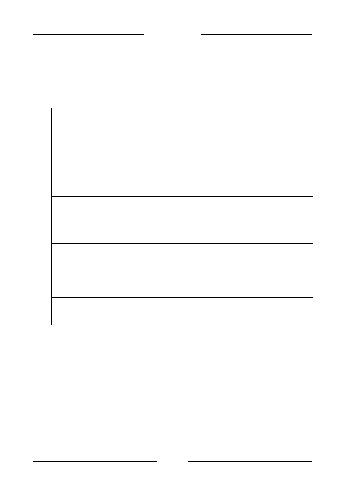
1.13 Spare parts
FIG.
REF.
CODE
DESCRIPTION
1.11-1
1
404602
POWER SUPPLY UNIT BOARD DC-DC 9-18, +15V FOR
DIGITAL SCALE
1.11-2
1
405841
DD1010 FLYNET MOTHERBOARD FOR COLIBRI T20 CORE
1.11-1/
1.11-2
2
404991
DD1010 FLYNET 5.7” SIZE LCD SUPPORT BOARD
1.11-1
3
47180119
MOTHER BOARD-“DIADE” SERIES ANALOGUE/DIGITAL
CONVERTER CONNECTION
1.11-2
3
47180230
MOTHER BOARD-ANALOGUE/DIGITAL CONVERTER DD1010
FLYNET STAINLESS STEEL VERSION CABLE GLAND L=20
CM
1.11-1
4
54830002
FLAT ZIF FPC 40 PIN PITCH 0.5MM TOP-TOP CONTACTS A
TYPE L=15 CM
1.11-2
4
54830006
FLAT ZIF FPC 40 PIN PITCH 0.5MM TOP-TOP CONTACTS A
TYPE L=35 CM
DD1010 FLYNET STAINLESS STEEL VERSION CABLE
GLANDS AND DIRECT OUTPUTS.
1.11-1
5
52050019
SWITCHING POWER SUPPLY UNIT 100-240VAC/12VDC
OUTPUT 12VDC/60WATT, IEC SOCKET, 2 FERRITE CABLE
AND 4-PIN CUSTOMISED POWERDIN OUTPUT CONNECTOR
1.11-2
5
52050034
SWITCHING POWER SUPPLY UNIT 88-264VAC/12VDC
IOUT=2.1A 25W, INSULATED INPUT/OUTPUT TERMINALS
DD1010 FLYNET STAINLESS STEEL VERSION CABLE
GLANDS
1.11-1
6
404701
DIGITAL CONV. BOARD FOR “DIADE” SERIES DIGITAL CELLS
1.11-1
7
57130086
BOARD CORE COLIBRI T20 512MB
1.11-1
8
47180129
MOTHER BOARD-“DIADE” SERIES DIGITAL CELL INTERFACE
CONNECTION
1.11-2
9
46050253
SIGMA-DELTA A/D CONV.UNIT COMPLETE WITH ZAMAK
CASING FOR ANALOGUE CELL
For other spare parts not listed, please refer to the Service Department.

15
DD1010 FLYNET
Figure 1.11-1 –Plastic indicator spare parts
Figure 1.11-2 - Stainless steel indicator spare parts
1
2
2
3
9
4
5
3
1
6
5
8
4
7

16
DD1010 FLYNET
2 SAFETY REQUIREMENTS
2.1 Not allowed uses
The equipment purchased is a metrological instrument intended for non-automatic weighing and as
such has been designed and manufactured. The primary use for which it is intended is the weighing
of goods.
It is forbidden to use the indicator without the necessary precautions for safe use.
It is forbidden to use the indicator in places with a potentially explosive atmosphere or in places
where fire hazard exists.
It is forbidden to use the indicator outside the environmental, electrical and metrological
conditions prescribed and indicated in this manual.
Misuse of the indicator or use with functions other than those for which it was manufactured is
prohibited.
Use is forbidden if it has not been correctly and completely installed in the site or place for which
it is intended.
Use is forbidden in case of non-compliance with power supply technical specifications.
Uses other than the one for which it has been designed and manufactured relating to non-automatic
weighing within the limits set by the manufacturer represent a misuse and are prohibited, unless
formally authorised by the Manufacturer.
2.2 Regulations
The conditions of use of the electronic indicator for weighing instruments are governed by the
regulations in force in the country of use.
Use under conditions that do not comply with these regulations is prohibited.
2.3 Conditions of use
Carefully follow this manual during use.
If you find any discrepancies between the contents of this manual and the equipment in your
possession, contact your Retailer or the After-Sales Service of the Manufacturer for clarification.
Strictly respect the indications on the warning and danger plates on the indicator.
Make sure that the indicator is complete with all the protections it has been provided for (cover
and protection devices) as shown in the technical drawings in the manual; before use and on a
regular basis, check also the integrity of the cables and their proper connection.
Make sure that the indicator is always connected to a power socket equipped with an effective
ground pin, checking that this line complies with the regulations in force in the country of use.
Make sure there is no difference in potential between ground and neutral.
If the indicator must be connected to other devices such as computers or other equipment,
disconnect them from the power supply before making the connections.
Any maintenance and/or repair work must only be carried out by authorised personnel.
Before carrying out any maintenance work, always disconnect the indicator from the power
supply and wait a few minutes before accessing its internal components.

17
DD1010 FLYNET
3 DELIVERY AND INSTALLATION
Figure 3-1 - Indicator bottom with connectors
Key:
1. Slots for optional boards
2. Scale 1
3. Scale 2
4. HDMI port (optional)
5. I/O port
6. COM4 port
7. COM6/ 7 port
8. Ethernet port 10/100 Mb/s
9. USB HOST ports
10. Serial board expansion (optional)
11. 12 V power supply (through external power supply unit)
1
2
3
6
7
8
9
11
5
10
4
18
DD1010 FLYNET
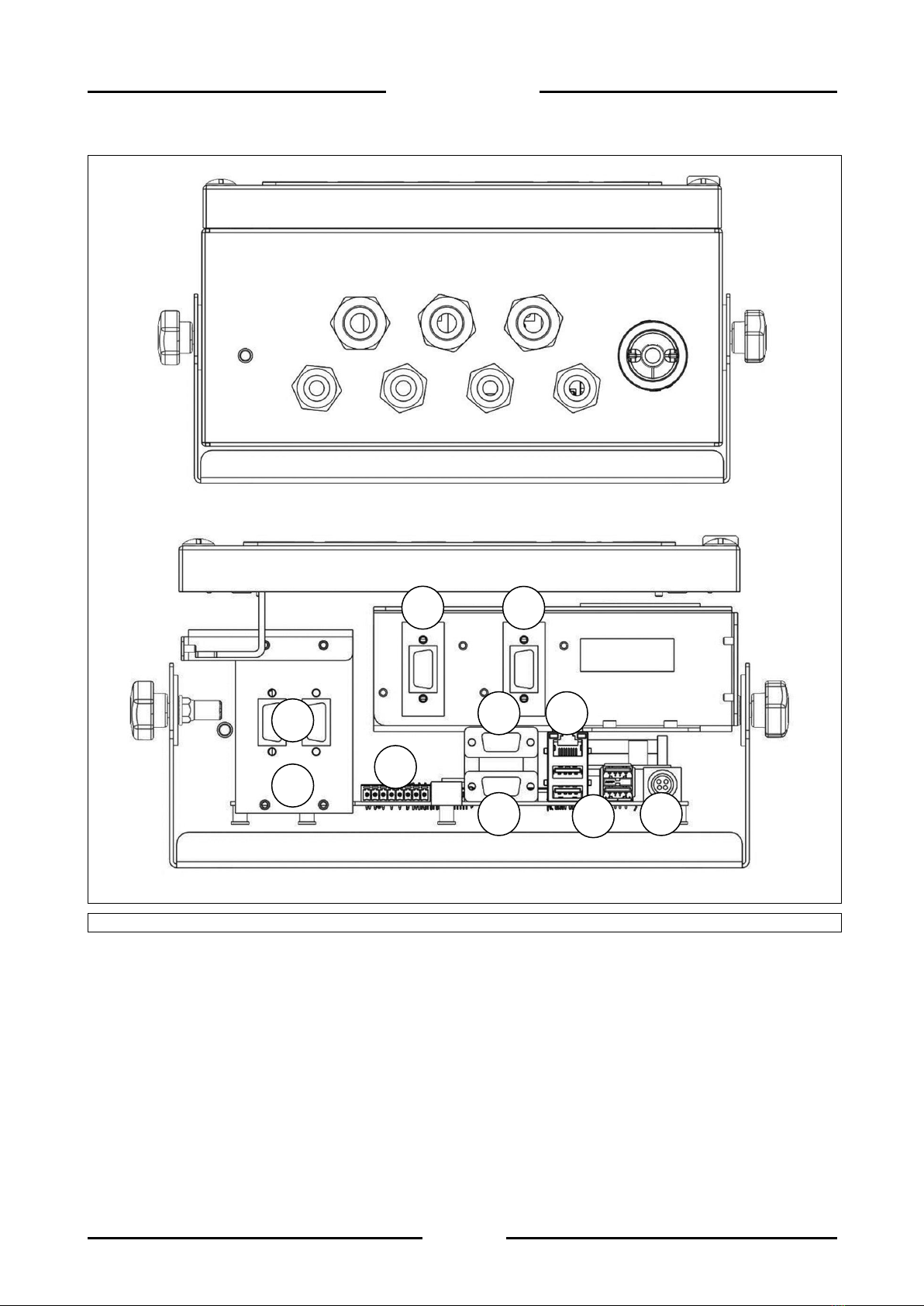
Figure 3-2 - Indicator bottom with cable glands
Key:
1. Slots for optional boards
2. Scale 1
3. Scale 2
4. I/O port
5. COM4 port
6. COM6/ 7 port
7. Ethernet port 10/100 Mb/s
8. USB HOST ports
9. Serial board expansion (optional)
10. 12 V power supply (through external power supply unit)
9
2
3
4
5
6
8
7
10
1
Other manuals for DD1010
4
Table of contents
Other Bilanciai Accessories manuals


Popular Accessories manuals by other brands


NeuLog
NeuLog NUL-203 quick start guide

Interlogix
Interlogix International Shock Sensor installation instructions

IFM
IFM PL205 Series operating instructions

brennenstuhl
brennenstuhl BrematicPRO BM 868 01 Instructions for use

Nootools II
Nootools II Ballmagnet Nstallation instructions

GTV
GTV AE-CM3M00-00 manual