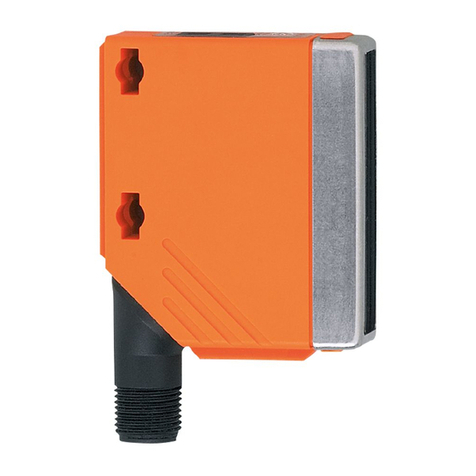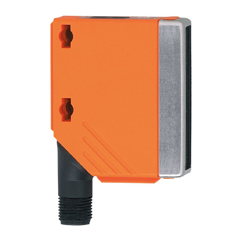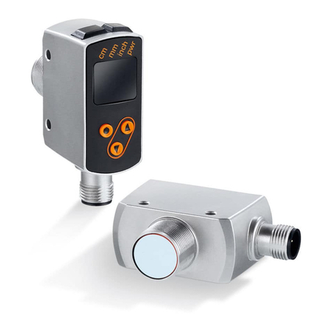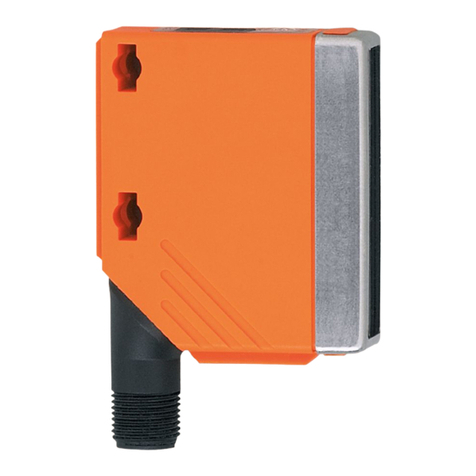
O1D111 Photoelectric distance sensor
2
Contents
1 Preliminary note ............................................................. 3
1.1 Symbols used.......................................................... 3
1.2 Warnings used ......................................................... 3
2 Safety instructions............................................................ 4
3 Intended use................................................................ 6
3.1 Applications ........................................................... 6
4 Functions .................................................................. 7
4.1 Output function hysteresis................................................. 7
4.2 Output function window................................................... 7
4.3 Analogue function mode.................................................. 7
4.4 Switch off the laser...................................................... 7
4.5 IO-Link ............................................................... 7
5 Installation.................................................................. 8
5.1 Installation conditions.................................................... 8
5.2 Mounting accessories.................................................... 8
6 Electrical connection.......................................................... 9
6.1 Operation with IO-Link master.............................................. 9
7 Operating and display elements................................................. 10
8 Menu...................................................................... 11
8.1 Menu structure ......................................................... 11
8.2 Explanation of the menu.................................................. 11
9 Operating modes ............................................................ 13
9.1 Run mode............................................................. 13
9.2 Display mode .......................................................... 13
9.3 Object reflectivity........................................................ 13
9.4 Programming mode...................................................... 13
10 Parameter setting............................................................ 14
10.1 General parameter setting................................................. 14
10.1.1 Setting a parameter value............................................. 14
10.1.2 Change from menu level 1 to menu level 2 . . . . . . . . . . . . . . . . . . . . . . . . . . . . . . . . 14
10.1.3 Electronic lock...................................................... 14
10.2 Configuration of the basic settings . . . . . . . . . . . . . . . . . . . . . . . . . . . . . . . . . . . . . . . . . . 15
10.2.1 Selection of the display unit............................................ 15
10.2.2 Set the display ..................................................... 15
10.2.3 Configure OUT1.................................................... 15
10.2.4 Hysteresis function.................................................. 15
10.2.5 Setting of the switch point for hysteresis function OUT1 . . . . . . . . . . . . . . . . . . . . . . 16
10.2.6 Window function.................................................... 16
10.2.7 Setting of the switch points for window function OUT1 . . . . . . . . . . . . . . . . . . . . . . . 17
10.2.8 Configure OUT2.................................................... 17
10.2.9 Setting of the switch point for hysteresis function OUT2 . . . . . . . . . . . . . . . . . . . . . . 18
10.2.10 Setting of the switch points for window function OUT2 . . . . . . . . . . . . . . . . . . . . . . . 18
10.2.11 Scaling of the measuring range (analogue output) . . . . . . . . . . . . . . . . . . . . . . . . . . 18
10.3 Teach mode........................................................... 19
10.3.1 Setting of the sampling rate............................................ 19
10.3.2 Setting of the repeatability............................................. 20
10.4 Extended functions...................................................... 20
10.4.1 Set the delay time for switching outputs . . . . . . . . . . . . . . . . . . . . . . . . . . . . . . . . . . 20
10.4.2 Setting of the fault suppression time for switching output / analogue output . . . . . . . 20
10.4.3 Reset all parameters to factory setting . . . . . . . . . . . . . . . . . . . . . . . . . . . . . . . . . . . 20
10.4.4 Display of the software version number. . . . . . . . . . . . . . . . . . . . . . . . . . . . . . . . . . . 21
11 Operation .................................................................. 22
11.1 Error indications ........................................................ 22
12 Maintenance, repair and disposal................................................ 23
