Bilanciai BTEK BS-FESD-P-CPR-M User manual

BS-FESD-P-CPR-M
BS-FESD-P-CPD-M BS-FECD-P-CPR-M
BS-FECD-P-CPD-M
Models Include:

www.B-TEK.com 2016
Pit Type Truck Scale Installation Manual
2

2016 www.B-TEK.com Pit Type Truck Scale Installation Manual 3
Contents
Introduction Page 4
Before Installation Page 5
Choosing a Site Page 6
Site Preparation / Foundation Page 7
Unpacking Page 7
Installation Page 8
Locating Plate Page 11
Lifting Modules into Place Page 11
Connecting Modules Page 14
Order of Module Installation Page 15
Conduit Installation Page 16
Concrete Deck Scale Preparation Page 17
Adjusting the Checking Page 18
Replacing the Dummy Load Cell Stands Page 18
Aligning the Load Cells Page 20
Connecting the Grounding Cables Page 21
Load Cell Cable Wiring Page 21
Maintenance Page 24
Spare Parts Page 24

www.B-TEK.com 2016
Pit Type Truck Scale Installation Manual
4
Introduction
This manual is meant as an installation guide for the B-TEK Pit Type series of full
electronic motor truck scales. This includes the following models:
BS-FESD-P-CPR-M
BS-FESD-P-CPD-M
BS-FECD-P-CPR-M
BS-FECD-P-CPD-M
The Pit Type series of at top truck scales are available in standard lengths from 10’ to 120’, and varying
widths from 8’ to 13’. Depending on how it was ordered, the individual scale modules can arrive from the
factory partially or fully assembled. This manual attempts to cover all instances.
All models fall under the NTEP certicate of conformance number 97-116A1.
No physical or electrical changes / alterations may be made to the scale during installation, which may void the
warranty. This includes removal, addition or modication of any steel or components, as well as electrical or
program related items.
Check with the local Weights and Measurements authority prior to installation to verify that the foundation
meets all requirements, including those of the National Institute of Standards and Technology (NIST) and spe-
cically Handbook 44.
Prior to installation it is the customer’s responsibility to verify that the equipment meets the requirements of
the application. Do not begin installation if this is unknown. It is the customer’s responsibility to ensure that the
scale equipment is operated within the manufacturer’s specications.
Any repairs must be performed by B-TEK Scales authorized service technicians.
Failure to comply with this policy voids all implied and/or written warranties.
General safety warnings are as follows:
• The scale is designed for vehicular trac only, do not allow any pedestrian trac on the scale
• Do not get out of your vehicle while on the scale
• Keep all hands, feet and clothing away from moving parts
• Do not exceed the specied load limit for the scale
• Do not use the scale for any other purpose than weight measurement
• Use caution when removing snow or other debris from scale deck or beneath the scale modules

2016 www.B-TEK.com Pit Type Truck Scale Installation Manual 5
Before Installation
Prior to installation verify the following:
• The scale design will meet the customer’s application correctly
• The scale is located so that vehicles can enter and exit easily
• There will be sucient drainage of water from the scale area
• The approaches on both ends are level and meet the requirements of NIST Handbook 44, requiring that the
rst 10’ is on the same plane of the platform
• Do not locate electrical components near any items with magnetic material. Additionally, do not locate
indicators in direct sunlight or in areas subject to extreme temperature changes as this may aect the accuracy
of the weighing.
• You have a copy of the scale and foundation drawings specic to this installation on site at the time of installation
• You have a copy of this manual on site at the time of installation
• The foundation concrete has had a full twenty-eight day period for proper curing
• All installation and calibration adjustments required for the scale to perform to its specied accuracy and
operation are considered to be part of the standard scale installation.
• Installations that cannot be nished in one session must ensure that proper signage and barriers are in place
to prevent use of the scale until fully operational

www.B-TEK.com 2016
Pit Type Truck Scale Installation Manual
6
Choosing a Site
The rst step in installing the scale is to choose an appropriate site. Pertinent steps in choosing the site are:
Ensure that the site has adequate approaching / exiting distance to comply with state and local Weights
and Measures regulations. Scale length and scale elevation (maximum fall per foot allowance) will
impact the total area requirement.
The site selected must meet state and local requirements. The following is taken directly from Handbook 44
(H-44) issued by the National Institute of Standards and Technology.
UR.2.6. Approaches
UR.2.6.1., Vehicle Scales - On the approach end or ends of a vehicle scale installed in any one
location for a period of six months or more, there shall be a straight approach as follows:
(a) The width at least the width of the platform, and
(b) the length at least one-half the length of the platform but not required to be more than 40 feet, and
(c) not less than 10 feet of any approach adjacent to the platform shall be constructed of concrete or
similar durable material to insure that this portion remains smooth and level and in the same plane
as the platform. However, rating of sucient strength to with stand all loads equal to the sectional
capacity of the scale may be installed in this portion. Any slope in the remaining portion of the
approach shall insure, 1) ease of vehicle access, 2) ease for testing purposes, and 3) drainage
away from the scale.
The scale drawings provided meet part (a) of this requirement. The site must be located to meet parts (b) and (c).
The site should have adequate room for trucks to properly align with the platform before pulling on. This is
especially important if trucks must turn before driving onto the scale.
Trucks should remain on the scale for a period of time no longer than is necessary for obtaining the vehicle
weight. Drivers / passengers / pedestrians should not exit their vehicles or use the scale platform as a walkway.
Some jurisdictions require that the scale platform be clearly visible from the location of the scale instrument.
Others will allow the use of closed circuit TV or even a voice intercom. Obtain ocial approval before starting
construction.
• Check all state and local Weights and Measures requirements before breaking ground to ensure compliance
with all regulations.
• Obtain all necessary permits for construction.
• Check all public utilities to ensure that your site is free of underground lines, pipes or hoses.
• Have assurance that the soil at the site is capable of withstanding a minimum pressure of 3,000 psf or as
specied on the B-TEK, Inc. drawing / print.
• Make sure the site does not intersect existing drains or utilities.
• All surrounding areas must drain away from the scale site.
• Ensure that all overhead objects (i.e. power lines, lights) do not interfere with unloading and setting the scale
modules with a crane.

2016 www.B-TEK.com Pit Type Truck Scale Installation Manual 7
Site Preparation / Foundation
Check and review all blueprints prior to starting work. Steps to follow include:
• Use only the latest engineering drawing sent with the scale order.
• Using a transit, locate the stakes where the scale foundation will be constructed.
• Excavate to the specied elevation on the drawing / print to comply with the desired nished scale elevation.
• Construct forms and make sure they are square, plumb, and level.
• Foundation must be accurate to the blueprints within specied tolerances. The foundation must comply with
the blueprint to have an acceptable installation.
• Position cut-to-length rebar into the foundation forms as per illustrations noted on the B-TEK Scales drawings.
(Rebar conforming to ASTM 615 Grade 60 is recommended.)
• Concrete of 4,000 psi compressive strength is required for the foundation, and piers, if used.
• The base plates, which support the load cells, are designed to be anchored to the foundation (or pier) by
using expansion bolts placed in concrete after curing.
• B-TEK Scales recommends the use of 3/4” X 7” length expansion bolts, which provide greater exibility, to
ensure proper positioning of the scale.
• All concrete work must meet standards set forth by the American Concrete Institute Code.
• Allow the concrete foundation time to cure before erecting the scale. Insucient curing time of concrete may
result in damage to the structural integrity of the scale foundation.
Unload the shipping crate of scale components prior
to unloading scale platform modules from the truck to
verify you have everything included on the packing
list.
Open all boxes for individual equipment pieces
and perform a physical inspection to be certain all
components are present and have not been dam-
aged during shipping. Any parts that are missing or
damaged must be reported immediately to qualify
for warranty replacement. Digital photos that can be
e-mailed are extremely helpful.
The components included in your Centurion or Hybrid
truck scale “package” will include: weighbridge mod-
ules, weighbridge connection fasteners, load cells
and load cell base plates, locating plates, shims, load cell cables, bumper checking assemblies, conduit, and
junction boxes with terminal boards. An indicator, printer, surge protection equipment, and 50’ of home run ca-
ble is included with digital Centurion models. Foundation drawings and an installation manual is included with
all scales. Concrete deck Centurions will include deck sheeting and rebar preinstalled at the factory.
Your Centurion truck scale “package” does not include foundation components such as concrete, rebar, mesh,
forms, deck coping, etc., freight charges, transportation and permit fees, or material handing and crane fees.
Unpacking
www.B-TEK.com 2016
Pit Type Truck Scale Installation Manual
8
Installation
Prior to installation of the scale it is important to have the proper tools and equipment. The following is a sug-
gested list :
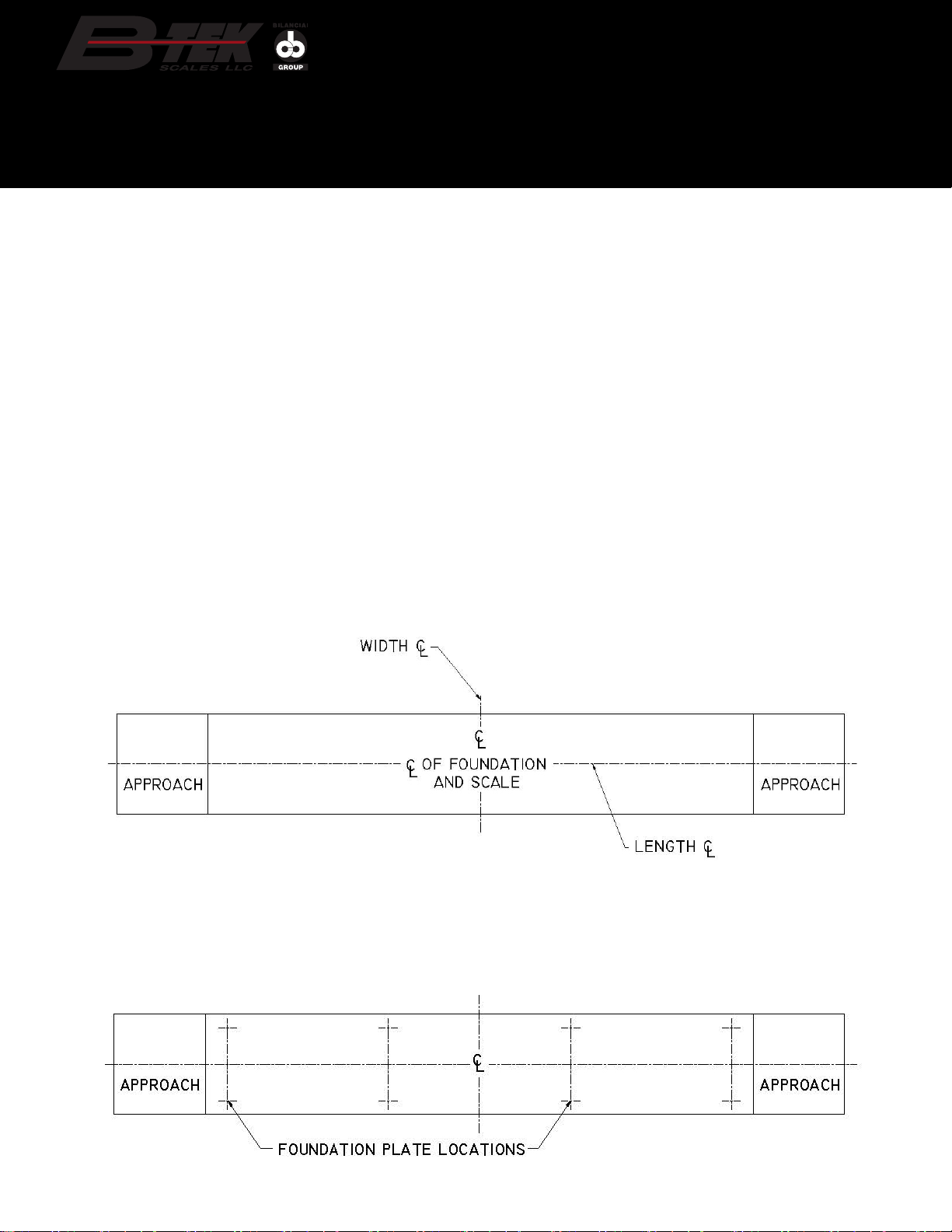
Layout the foundation base plate locations using the foundation drawing specic to the scale’s installation.
Snap chalk lines to mark the center locations of all load cell foundation base plates. Note that all center lines
should be measured from center of foundation. The foundation base plates have the width and length
centers marked with a punch.
• Foundation drawings
• 4-way lifting chains with of 15’ - 20’
lengths to each corner
• 100’ measuring tape
• Chalk line
• Laser level and/or transit
• Hydraulic jack(s)
• Dummy load cells
• Various size wrenches and sockets
(13mm, 9/16”, 3/4”, 1-1/8”, 1-5/16” and 1-7/8”)
• Pry bars
• Hand tools for working with cables / wires
• Level(s)
Foundation Base Plate Layout
Verify that the foundation dimensions are correct and accurate, specically the distance between end walls and
the vertical height from slab / pier to top of approach.
The foundation must be square. Verify by marking centerlines of both the length and width of foundation with a
chalk line. Use the foundation drawing supplied for reference. All measurements should be taken o of these
centerlines.

2016 www.B-TEK.com Pit Type Truck Scale Installation Manual 9
Shim plates (if needed)
(old style shown, New style
included with scale 5/2016)
Center Line
Center Line
Foundation Base Plate
Center Marks
Note that the foundation base plates will be a combination of basic plates and combination plates that have the
checking assemblies included as shown below.
BASIC BASE PLATE COMBINATION BASE PLATE
with SIDE CHECKING (four per scale)

www.B-TEK.com 2016
Pit Type Truck Scale Installation Manual
10
For each load cell in the scale, a load cell mount kit will be provided. It consists of the following:
• Lower receiver
• Upper Receiver
• (2) 1/16” thick shim plates - #100-66458-2
• (2) 1/8” thick shim plates - #100-66458
• Isolation disc
• Debris foam ring
• (2) grounding straps
• (1) bag containing anti-rotation pin
Note that scale height dimension shown on the supplied drawings include the 1/8” ring plate and both 1/16”
shim plates in the overall stack height. Should additional height need to be made up, an additional 1/8” shim,
part #100-66458, is included for each load cell location.
Load Cell Mount Kit
Anti-Rotation Pin
Debris Foam Ring
Lower Receiver
Isolation Ring
Upper Receiver
Grounding Straps
Shim Plates
It is recommended to layout all foundation base plates
prior to permanently anchoring to the foundation. Set
the foundation plates in place. Do not secure the plates
to the foundation at this time.
Ensure that the foundation base plates are all level with
each other. Shim plates for use on the top of the foun-
dation base plates are included.
Shim plates are 1/8” in thickness and are meant to
make up minor dierences in height. The acceptable
height tolerance between all base plates is +/- 1/8”.
Verify with a laser level or transit
If the amount of the dierence in height between the
base plates cannot be made up with the use of the
shim plates alone, use non-shrinking grout under the
base plate to bring them uniform in height and/or level
with the other base plates.
Ring Plate Plate Hardware

2016 www.B-TEK.com Pit Type Truck Scale Installation Manual 11
Locating Plate
Secure the load cell locating plates to the foundation base plates using the included hex head bolts (2) M12 X
40mm and (1) M8 X 40mm, lock nuts and at washers.
Starting with the rst 4-cell module locating plates, place a dummy load cell assembly into the base ring of
each locating plate.
Lifting Modules into Place
If the scale is a concrete deck version it will have
lifting lugs permanently attached to the weighbridge.
Refer to the following sections for shoring and
crowning instructions prior to lifting the modules into
place.
The rst module to be placed onto the foundation is
an end module which should be placed directly after
the end wall. The four dummy mount assemblies
should already be in place on the base plates located
on the chalk line centers on the foundation.
Prior to lifting the end module, attach two 8-hole
mounting plates to the end of the module closest to
the center of the scale. It is suggested to mark a
centerline across the width of the mounting plate.
This helps to visually line up the 1/4” gap that should
be between the two modules when tightening the
mounting plates, and later the splice plates.
Locating Plate with Dummy Cell
8-Hole Upper Reciever Plate
8-HOLE UPPER RECEIVER PLATE
SHOWN with OUTLINE OF BEAMS
when installed

www.B-TEK.com 2016
Pit Type Truck Scale Installation Manual
12
Completely tighten the four 3/4” mounting bolts and nuts through the
four holes on the bottom ange of main beams of the end module. The
end closest to the end wall has the mounting plates welded to the
bottom anges of the main beams.
Secure the 4-way chains from the
crane to crossmembers or the outrig-
gers that are welded to the sides of the
weighbridge module.
Prior to installing the weighbridge mod-
ule onto the dummy load cell stands
ensure that safety supports such as
wood blocking is placed under the
weighbridge module being lifted.
Lift the end module with the 8-hole upper receiver plate already bolted in place over the four dummy cell stand
assemblies and slowly lower the module so that the button on top of each dummy stand is inserted into the thru
hole located in each mounting plate. Hydraulic jacks can be also be used to help position the modules onto the
dummy stands.
End Module Upper Receiver Plate Shown
with Load Cell Mount Assembly 8-Hole Upper Receiver Plate Shown
with Load Cell Mount Assembly

2016 www.B-TEK.com Pit Type Truck Scale Installation Manual 13
Verify that all four dummy stands are inserted concentrically in the mounting plate thru holes with no binding
and that the bridge rests at on top of the dummy cell pin.
LOAD CELL / DUMMY STAND ALIGNMENT
Once the rst end module is in place on the dummy stands take a measurement from the end of the module’s
main beam to the pit’s end wall. This measurement should be 1-1/4”. Take this measurement from both main
beams to the pit wall to ensure that the distance is the same and that the module is parallel with the end wall.
The measurements should be within 1/8” of each other. If they are not, adjust the module by leveraging a pry
bar between the module and end wall to achieve squareness.
The end modules are shipped from the factory with the end bumpers and 3/8” thick backing plates installed. If
additional bumper thickness is needed, additional 1/4” and 1/8” bumper shims are shipped loose and can be
installed behind the poly block bumpers.
Final adjustments to the bumpers can be made once all of the modules have been installed and connected to
one another.

www.B-TEK.com 2016
Pit Type Truck Scale Installation Manual
14
Bolted Mounting Plate Shown
with Load Cell Mount Assembly
Connecting Modules
With the rst end module in place you can now lift the next adjoining module into place and attach using the
mounting plates and splice plates. If the adjoining module is a center module, attach another set of 8-hole
mounting plates to the end of the module farthest from the end wall you started at.
The module will be lowered onto the 8-hole upper receiver plate connected to the end module that was in-
stalled rst, and onto the dummy stands at the opposite end.
Once lowered onto the rst module’s 8-hole upper receiver plates you may insert the remaining four mount-
ing bolts into the bottom ange of both main beams on that end of the module. You will then attach the splice
plates by bolting them with 7/8” bolts through the web of the adjacent main beams of the connecting modules.
Lower the last module into place with the end that has the welded mounting plates located closest to the end
wall, and the end with the mounting and splice plate holes mating with the connecting module.
The module will be lowered onto the 8-hole mounting plate connected to the adjacent module and onto the
dummy stands at the opposite end. Install the remaining hardware in the mounting plates and then install the
remaining splice plates between the last modules.
Take a measurement of the distance between the last module’s main beams and the pit’s end wall. This mea-
surement should be 1-1/4”. Take this measurement from both main beams to the pit wall to ensure that the
distance is the same and that the module is parallel with the end wall. The measurements should be within 1/8”
of each other. If they are not, adjust the module by leveraging a pry bar between the module and end wall to
achieve squareness.
The end modules are shipped from the factory with the end bumpers and 3/8” thick backing plates installed. If
additional bumper thickness is needed, additional 1/4” and 1/8” bumper shims are shipped loose and can be
installed behind the poly block bumpers.
Bolted Splices Plate Shown
with Load Cell Mount Assembly

2016 www.B-TEK.com Pit Type Truck Scale Installation Manual 15
Typical installation order of individual Pit Type modules
1. Module starting at end wall location
2. Module resting on mounting plate of rst module and subsequent modules will rest on second module’s
mounting plates
3. Last module rest on previous module’s mounting plate welded mounting plate next to the end wall 4-cell
module starting at end wall location

www.B-TEK.com 2016
Pit Type Truck Scale Installation Manual
16
Conduit Installation
Once the scale modules are in place on the dummy stands, you will want to install the conduit for load cell cables
prior to attaching the steel deck plates or preparing the scale for a concrete deck pour.
The conduit is shipped loose in 10’ lengths. Conduit must be cut to length in the eld as needed for the scale’s
length and width. Enough conduit is supplied for the scale length and width at each load cell location.
Conduit clamps are included as well, with larger beam clamps for connecting to main beams, and slightly smaller
clamps for connecting to crossmembers. Three clamps should be used for each ten foot section of conduit.

2016 www.B-TEK.com Pit Type Truck Scale Installation Manual 17
Concrete Deck Scale Preperation
Shoring Instructions
A B-TEK pit style concrete deck weighbridge module requires proper shoring prior to pouring the deck. This will
help support the bottom deck pan until the concrete hardens. If you have questions about the shoring proce-
dure, please call B-TEK scales at 800.266.8900.
• The standard B-TEK pit style concrete deck scale typically has the deck sheeting laid just lower than the top
ange of the main beams. Shoring / blocking under the sheeting is required prior to pouring the concrete.
• Typically, 2” x 6” lumber is recommended to be used to support the sheeting. Cut a piece of lumber the same
length as the measurement between the web of the two main beams. This will act as a temporary crossmember
under the sheeting. You will need to notch the two top corners to avoid interference with the radii between the
top ange and web.
• Cut two additional pieces of lumber to support both ends of the crossmember. These pieces will t between
the bottom of the wooden crossmember support and the top side of the bottom ange of the main beams. This
distance may vary. Take a measurement to ensure the proper lengths to be cut.
• The wooden crossmember and its two supports should be placed evenly between each set of steel
crossmembers in the weighbridge. The wooden supports can be removed once the concrete hardens.
After pouring the concrete the use of a pencil-type vibrator is required to ensure that the concrete is completely
settled and all voids have been lled.
It is important that the concrete deck is given proper curing time. Loading the scale deck prior to its full curing
may result in damage or failure to the structural integrity of the scale deck.

www.B-TEK.com 2016
Pit Type Truck Scale Installation Manual
18
Adjusting the Checking
Once assembled, verify that the scale is centered in the foundation. If it is not, make the appropriate adjust-
ments. With the modules bolted together, adjust the end bumper checking and the side checking stands. The
poly bumpers on the end wall, and the bolt heads on the side checking stands should be approximately 1/16”-
1/8” away from the end wall and scale structure respectively.
Replacing the Dummy Load Cell Stands
Once the end and side checking has been adjusted the dummy load cell stands will need to be removed and
replaced with the actual load cells. It is imperative that the checking has been adjusted to minimize the lateral
movement of the weighbridges when replacing the stands.
Prior to lifting a module / weighbridge place safety blocking under one of the main weighbridge
structural beams with approximately 1/2” gap between the block and bottom of the beam. This will stop
the module from falling to the foundation in the case of a stand or load cell falling over.
Starting with a load cell dummy stand in the rst end module, use a hydraulic jack to lift the weighbridge in a
location close to the stand being removed. Place the jack under the outermost beam for the lifting location.
Note that on concrete deck scales that have already been poured, it is recommended to use two hydraulic
jacks placed on opposite sides of the module to lift the module in a level position. Lifting the module unevenly,
mid-section or between load cell locations will cause cracks in the concrete.

2016 www.B-TEK.com Pit Type Truck Scale Installation Manual 19
Wood safety blocking under weighbridge modules
Once the dummy load cell stand has been removed, replace with the load cell. Assembly per the diagram below:
Start by placing the ceramic isolation
disc into the circular ring which is part of
the locating plate. The load cell bottom
cup is then placed inside the isolation
disc, with the anti-rotation pin insert into
the cup’s blind hole.
Using the supplied tube of grease,
spread a moderate amount of grease
on the top button of the load cell bottom
cup.
Slide the foam ring over the top of the
load cell bottom cup, aligning with the
antirotation pin that is protruding.
Place the load cell onto the assembly,
taking care that thenotch in the bottom
of the load cell aligns with the anti-rota-
tion pin. The cable connector on the load cell should face the center of the scale towards the conduit.
Using the supplied tube of grease, spread a moderate amount of grease on the top button of the load cell where it
ts into the recess of the mounting plate.
Slowly release the jack to lower the module, with the load cell top cup’s button seating in the thru hole of the mod-
ule’s mounting plate.

www.B-TEK.com 2016
Pit Type Truck Scale Installation Manual
20
Aligning the Load Cells
After all cells have been installed adjust the end bumper assembly out till they just meet the wall. This will
restrict weighbridge movement during the leveling of load cells. Once the load cell assembly has been installed
it must be checked for correct alignment. Using the B-TEK load cell surface level, supplied to authorized deal-
ers, attach to the lower diameter of the load cell using the integral magnet. The magnet can be adjusted in and
out by turning the set screw.
With the level attached to the load cell, verify that the load cell is aligned
both horizontally and vertically by ensuring that the air bubble is visible
between marked lines.
If the load cell is out of level, adjustments can be made by realigning the
foundation base plate.
Repeat the check with the level to verify that the load cell is aligned
correctly.
Continue to readjust the locating plate as needed.
B-TEK Load Cell Surface Level
Once the entire scale has had the load cell assemblies installed and aligned correctly, readjust all bumper
checking assemblies to within 1/16” - 1/8”. Prior to drilling, make sure that all deck / cover plates are aligned
and bolted.
At this time drill and install all of the anchors for the base plates. Anchors are suggested to be 3/4” X 7” long
wedge anchors. A 3/4” X 36” long drill bit can be used for the holes.
Load Cell Assembly Anchored to Foundation Load Cell Level
This manual suits for next models
3
Table of contents
Other Bilanciai Scale manuals


