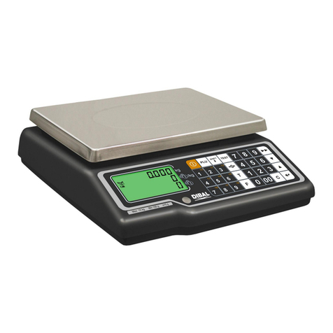
Bilanciai DD700ic User manual

DD700 Weighing Terminal
Use and Maintenance Manual
Code 81320458
Issue 29/08/2022

2
USE AND MAINTENANCE MANUAL
CONTENTS
1INTRODUCTION...............................................................................................................................5
1.1 Foreword............................................................................................................................................5
1.2 Documentation...................................................................................................................................6
1.3 Symbols.............................................................................................................................................6
1.4 Description of the terminal.................................................................................................................7
1.5 Key ....................................................................................................................................................7
1.6 Technical features of the terminal......................................................................................................8
1.7 Declaration of conformity...................................................................................................................9
1.8 Overall dimensions and weight of terminal ......................................................................................10
1.8.1 Plastic version ...................................................................................................................10
1.8.2 Tabletop stainless steel version ........................................................................................10
1.8.3 Wall-mounted stainless steel version ................................................................................11
1.8.4 Panel mount version..........................................................................................................11
1.9 Instructions for the disposal of electric or electronic waste..............................................................12
1.10 Instructions for requesting technical assistance...............................................................................12
1.11 Warranty..........................................................................................................................................12
2SAFETY PRESCRIPTIONS.............................................................................................................13
2.1 Prohibited use..................................................................................................................................13
2.2 Standards ........................................................................................................................................13
2.3 Instructions for use ..........................................................................................................................13
3DELIVERY AND INSTALLATION....................................................................................................14
3.1 Installation........................................................................................................................................17
3.1.1 Tabletop installation...........................................................................................................17
3.2 Connecting terminal to electric mains..............................................................................................17
3.2.1 Verifications.......................................................................................................................17
3.2.2 Connection diagram (version with connectors and ABS)...................................................18
3.2.3 Connection diagram (DD700 version with cable gland).....................................................19
3.3 Connecting terminal to weighing platform........................................................................................21
3.3.1 Connection diagram (with platform)...................................................................................22
3.3.2 Equipotential between terminal and weighing platform......................................................22
3.3.3 Digital Scale serial connection...........................................................................................23
3.3.4 Analogue Scale serial connection...........................................................................................23
3.4 Serial connections ...........................................................................................................................24
3.4.1 Serial output connection COM1.........................................................................................24
3.4.2 Serial output connection COM2 in RS422 configuration....................................................25
3.4.3 RS232 connections ...........................................................................................................26
3.4.4 RS422 connections ...........................................................................................................26
3.4.5 Serial output connection COM2 in RS485 configuration....................................................27
3.4.6 RS485 connections ...........................................................................................................27
3.4.7 USB Connections..............................................................................................................28
3.5 Input/Output Connection....................................................................................................29
3.5.2 Input connection................................................................................................................30
3.5.3 Output connection .............................................................................................................30
4COMMANDS, SWITCH ON AND OFF ............................................................................................31
4.1 On-off key........................................................................................................................................31
4.1.1 Selection display signals to display ...................................................................................34
4.2 Metrologic keys................................................................................................................................35
4.3 Alphanumerical keys........................................................................................................................36
4.4 On-off key........................................................................................................................................36
5. USING THE TERMINAL..................................................................................................................37
5.1 General information .........................................................................................................................37
5.1.1 Using the keys for browsing the menus.............................................................................37
5.1.2 Entering numerical data (Editor)........................................................................................38
5.1.3 Entering alphanumerical data............................................................................................38
5.1.4 Hotkeys .............................................................................................................................39
5.1.5 DD700 with external USB keyboard..................................................................................40

3
USE AND MAINTENANCE MANUAL
5.2 Functioning of Single weighing operation, Double weighing, Sum weighing, Load extraction, Unload
extraction, CPE functioning, Manual Selector, Weight Check and Multi-Operator...........................41
5.2.1 Single Weighing Operation (*) (***)....................................................................................41
5.2.2 Double Weighing Operation (*)..........................................................................................41
Operation with input and output weighing........................................................................................41
Input/output operation with Data Recall...........................................................................................41
Input operations...............................................................................................................................42
Output operations............................................................................................................................42
Recovering unused RcD codes .......................................................................................................43
Input/output operation with Plate Data Recall..................................................................................44
Delete RCPD code ..........................................................................................................................44
5.2.2.2 Operation with preset weights...........................................................................................44
Preparing the list of preset weights..................................................................................................45
Weighing operations with preset weights.........................................................................................45
5.2.2.3 Operation with the first weight being entered manually.....................................................45
5.2.2.4 Totals management...........................................................................................................45
5.2.3 Sum Weighing operation...................................................................................................46
5.2.4 Load Extraction operation (*) (***) .....................................................................................47
5.2.5 Unload Extraction operation (*) (***)..................................................................................48
5.2.6 Manual selection mode operation (**)................................................................................49
5.2.6.1 Classification display.........................................................................................................49
5.2.6.2 Range setting ....................................................................................................................49
5.2.6.3 Totalling by classification...................................................................................................49
5.2.6.4 Automatic print/transmission .............................................................................................49
5.2.7 Piece counter mode operation (**).....................................................................................50
5.2.7.1 AUW Management............................................................................................................50
5.2.7.2 Product code archive.........................................................................................................50
5.2.7.3 Product code totals archive...............................................................................................50
5.2.8 Multi-operator Operation (**) .............................................................................................51
5.2.8.1 Operator Archive ...............................................................................................................51
5.2.8.2 Operator Total Archive ......................................................................................................51
5.2.8.3 Print Archive......................................................................................................................52
5.2.8.4 Stop working (receipt closure)...........................................................................................52
5.2.8.5 Cancellation of weighing operation....................................................................................53
5.2.8.6 Single weighing print .........................................................................................................53
5.2.9 Weight Check Operation (**) .............................................................................................54
5.2.9.1 Display of Range and default values to process the limits (in divisions)............................54
5.2.9.2 Weighing limit entry...........................................................................................................56
5.2.10 MPP accessory operation..................................................................................................56
5.3 User menu.......................................................................................................................................57
5.3.1 User menu tree..................................................................................................................57
5.3.2 Modify date and time.........................................................................................................62
5.3.3 Weight display...................................................................................................................62
5.3.4 Memory status...................................................................................................................63
5.3.5 Reprint...............................................................................................................................64
5.3.6 Diagnostics (only for digital scale).....................................................................................64
5.3.7 Digital Cells (only if present)..............................................................................................64
5.3.8 Contrast adjustment ..........................................................................................................64
5.3.9 Setting output as set-point (if enabled...............................................................................64
5.3.10 Setting output as Range (if enabled).................................................................................65
5.3.11 Generic or Client code.......................................................................................................65
5.3.11.1 Generic.............................................................................................................................65
5.3.11.2 Client.................................................................................................................................65
5.3.12 Product code .....................................................................................................................65
5.3.13 Product codes list..............................................................................................................67
5.3.14 Preset tares.......................................................................................................................67
5.3.15 Preset tares list..................................................................................................................68
5.3.16 Progressive number ..........................................................................................................68
5.3.17 Coefficient Management....................................................................................................68
5.3.18 Totals Management...........................................................................................................69
5.3.19 Scale Selection (**) (***)....................................................................................................70
5.3.20 Lighting..............................................................................................................................71
5.3.21 Auto switch off...................................................................................................................71
5.3.22 Change unit of measurement (if enabled) ........................................................................71
5.3.23 Menu access-Modif.Arch./Password .................................................................................71
5.3.24 Weighing operation............................................................................................................71
5.3.25 Printer Cut .........................................................................................................................72

4
USE AND MAINTENANCE MANUAL
5.3.26 External battery voltage.....................................................................................................72
5.3.27 Archives <-->PC/USB........................................................................................................72
5.3.28 Printing weighing data.......................................................................................................75
5.3.28.1 Reprinting weighing data..................................................................................................76
5.3.29 Activate Buzzer..................................................................................................................76
5.3.30 Product Code Archive........................................................................................................76
5.3.31 Product Code totals Archive (*)(***)...................................................................................76
5.3.32 Product Code totals Archive (**)........................................................................................77
5.3.33 Printing operation (*) (***)..................................................................................................77
5.3.34 Printing operation (**)........................................................................................................77
5.3.35 Automatic print/transmission (**) .......................................................................................78
5.3.36 High Resolution.................................................................................................................78
5.3.37 Fieldbus/Modbus RTU.......................................................................................................78
6. OPTIONS.........................................................................................................................................79
6.1 MPP memory expansion boards......................................................................................................79
6.1.1 Memory capacity ...............................................................................................................79
6.1.2 Operation...........................................................................................................................79
6.1.3 MPP deactivation...............................................................................................................80
6.1.4 Checking stored weight data .............................................................................................80
6.2 Analogue output board ....................................................................................................................81
6.3 Serial expansion board....................................................................................................................81
6.4 Optional 4 Input/ 4Output board.......................................................................................................83
6.5 Ethernet Board 10/100 Mbit.............................................................................................................84
6.6 Profibus DP Board...........................................................................................................................84
6.7 Ethernet/IP Board............................................................................................................................84
6.8 Level (**)..........................................................................................................................................84
7TROUBLESHOOTING.....................................................................................................................85
7.1 Malfunctions.....................................................................................................................................85
7.2 Error Messages ...............................................................................................................................86
7.2.1 Memory Fill Message..............................................................................................................87

5
USE AND MAINTENANCE MANUAL
1 INTRODUCTION
1.1 Foreword
•The purpose of this manual is to instruct the operator on the prescriptions and essential criteria
for the installation, safe use and methodical maintenance of the weighing system, using texts
and figures supporting the explanations.
•Always keep this manual at hand! Always respect the instructions found in this document!
•The operating safety of the system is first of all entrusted to the operator, who must have an in-
depth knowledge of it.
•The user is responsible for making sure that installation complies with relevant standards in
force.
•The appliance must only be installed by specialist personnel after having read and understood
this manual.
•By "specialist personnel" we mean personnel who, following training and professional
experience, are expressly authorised by the "Safety manager of the system" to perform its
installation, operation and maintenance.
•Contact the closest Assistance Centre when you encounter any fault.
•The user or unauthorised personnel are prohibited from attempting any disassembly,
modifications or tampering with this system; this would make the warranty immediately null and
void and the Manufacturer would not be held liable for any personal harm or property damage it
may have caused.
•Alterations or removal of the data on the terminal's nameplates, seals or legalisation stamps is
also prohibited; therefore make sure that all the nameplates are in place and legible, or else
contact the After-Sales Service.
•The Manufacturer will not be held liable for damage resulting from careless handling of the
terminal.
•The following information and illustrations are updated to the date of issue.
The Manufacturer is committed to constantly improving its products, thus possibly modifying
some components of the system or parts of the software.
•All the technical information contained in this manual is the exclusive property of the
Manufacturer and must be considered as being of a reserved nature.
•The reproduction and disclosure, even partial, of this manual on paper, digital support or on the
WEB without written consent from the Manufacturer is prohibited.
•Use of this manual for purposes other than those strictly linked to the installation, use and
maintenance of the terminal is also prohibited.
•Some illustrations could represent the weighing system without safety guards in order to more
clearly and effectively detail operation, adjustments etc. Do not use the system in these
conditions. Only remove these safety guards for the time strictly necessary to perform the
required repairs or maintenance, then restore them immediately.

6
USE AND MAINTENANCE MANUAL
1.2 Documentation
The DD700 terminal is supplied with the following standard documentation:
•QUICK START
Multi-language, printed on paper, brief instructions for immediate use, declaration of conformity
and main danger warnings.
•USE, MAINTENANCE AND INSTALLATION MANUAL
Multi-language, in PDF format, may be printed on demand.
•MANUAL OF THE APPLICATION AND PARAMETERS
Multi-language, in PDF format, may be printed on demand.
Contact the After Sales service of our Sales and Support network
1.3 Symbols
The following symbols are used in the manual to call the reader's attention to the different danger
levels in the "Use and maintenance" of the instrument.
DANGER
Information or procedure which, if not carried out exactly, can cause death or severe personal
harm.
ATTENTION
Information or procedure which, if not carried out exactly, could cause minor personal injuries or
damage to the instrument.
WARNING
Information or procedure advising the operator on the ideal use of the system to extend its life
time, to avoid damage or loss of programming and to optimise work in compliance with metric
standards.
TECHNICAL ASSISTANCE
The sections bearing the following pictogram on the side are of the exclusive competence of a
qualified technician made available by the manufacturer for complex operations in particular
situations. Depending on the cases, these competences are mechanical and/or electrical and/or
electronic and/or regarding software. IT IS STRICTLY FORBIDDEN TO PERFORM THESE
OPERATIONS! RISK OF INJURY OR OF DAMAGING THE MACHINE!

7
USE AND MAINTENANCE MANUAL
1.4 Description of the terminal
The DD700 terminal performs extremely accurate and reliable weighing operations.
•Designed for industrial applications.
•Supplied as per standard with weighing management metrologic software.
•Body in ABS and stainless steel; available both in tabletop and wall-mounted versions.
•Versatile and customisable functions and graphical appearance.
•Advanced network connectivity and communication.
•Programming and customisation by networked PC.
1.5 Key
This manual refers to operations found in different models defined at time of purchase. The symbols
used in this manual are found hereunder.
*
Model "1" operating in: single weighing, sum weighing, extraction during
loading, extraction during unloading and double weighing.
**
Model "2" operating in: standard, piece count, sum weighing, manual
selector, weight check and extraction during unloading and multi-operator.
***
Model "3", see model "1" with selection management of scale "A" or "B" by
exclusion.
Unless specified, it is found in all models.

8
USE AND MAINTENANCE MANUAL
1.6 Technical features of the terminal
Power supply
Direct
12 VDC/4 A
Through mains adaptor
L+N+R
110 - 240 Vac (-15% … +10%)
1.8 A
50 - 60 Hz
60W Max
Earth socket
Equipotential for weighbridge
Scales
Total
1 analogue, 2 analogue multiplexing or 1 digital
Repeater operation
Repeater function
Analogue scale
Connectable load cells
Up to 12 x 350 ohm analogue load cells per
analogue converter
Minimum impedance
29 ohm per scale
Load cell power supply
5 VDC
Internal resolution
1000000 dots at 10 Hz
Resolution in type-approved version
Two 4000 ranges, three 3000 ranges
Maximum input signal
30 mV
Sensitivity
0.5 µV/division
Full scale stability
< 5 ppm/°C
Zero stability
< 5 ppm/°C
Digital scale
Connectable load cells
Up to one 12 digital load cells per digital
converter
Minimum impedance
80 ohm
Load cell power supply
10 ÷ 15 Vdc
Internal resolution
200000 dots @ 25 conv/sec
Resolution in type-approved version
Two 4000 ranges, three 3000 ranges
Environmental features
Compensated temperature range
From -10 to +40°C
Operating range
From -10 to +40°C
Maximum humidity
85% @ 40 °C
Protection rate IP
Plastic version and stainless steel version with
connectors: direct outputs IP 20 and front panel
IP 65.
Stainless steel version with cable glands IP 69K
User interface
Monitor
White LED backlit display
Keyboard

9
USE AND MAINTENANCE MANUAL
Communication ports
USB Device
1
USB Host
1
Serial ports
1 RS232 - 1 RS232/ RS422 /RS485
Inputs - Outputs
2+2
Memories
Optional MPP board
1
Expansions
Slot for optional boards
2
Optional boards
Optional opto-isolated RS232, RS422/RS485
serial board
PROFIBUS DP expansion board
EtherNet/IP expansion board
0-10V / 4-20mA analogue output board
WiFi 10/100 Mbit/sec board
Ethernet 10/100 Mbit/sec board
MPP memory expansion board
LED BAR board (only for IP69K )
1.7 Declaration of conformity
See QUICK START manual.

10
USE AND MAINTENANCE MANUAL
1.8 Overall dimensions and weight of terminal
1.8.1 Plastic version
Figure 1.8-1 - Dimensions of plastic weighing terminal
•Dimensions (expressed in mm): see figure 1.7.1.
•Weight: 1.5 Kg
1.8.2 Tabletop stainless steel version
Figure 1.8-2 - Dimensions of tabletop stainless steel weighing terminal
•Dimensions (expressed in mm): see figure 1.7.2.
•Weight: 4 Kg

11
USE AND MAINTENANCE MANUAL
1.8.3 Wall-mounted stainless steel version
Figure 1.8-2 - Dimensions of wall-mounted stainless steel weighing terminal
•Dimensions (expressed in mm): see figure 1.7.3.
•Weight: 4 Kg
1.8.4 Panel mount version
Figura 1.8-4 - Dimensions of the weighing terminal panel mount
•Dimensions (expressed in mm): see figure 1.8.4.
•Weight: 2,5 Kg

12
USE AND MAINTENANCE MANUAL
1.9 Instructions for the disposal of electric or electronic waste
This symbol on the purchased weighing instrument indicates that:
•This electric or electronic appliance cannot be disposed of as
municipal solid waste.
•It must be disposed of separately.
•It can be returned to the distributor when purchasing a new one.
•Improper use or disposal of this appliance can cause environmental
pollution or damage to health.
•Failure to comply with the indications above is sanctioned according
to standards in force.
In particular:
•The outer enclosure and the mechanical components are made up of plastic and/or metal
materials.
•There are printed circuit boards with electronic components inside the enclosure.
•The electrical connections are implemented with insulated copper conductors.
ATTENTION
Dispose of this appliance via separate waste collection either handing it over to the distributor or
to separate waste collection centres.
1.10 Instructions for requesting technical assistance
In the event of an operating fault or failure requiring intervention of specialist technicians, contact
your closest assistant centre or directly contact the manufacturer.
To speed up problem solving, communicate the serial number of the instrument found on the
stamped plate.
Also communicate the features of the system in which the terminal is installed.
1.11 Warranty
The clauses of the warranty are specified in the sales contract.

13
USE AND MAINTENANCE MANUAL
2 SAFETY PRESCRIPTIONS
2.1 Prohibited use
The purchased instrument is a weighing system and has been designed and manufactured as such.
It is intended primarily for weighing goods.
•it is prohibited to use the terminal without taking the necessary precautions for its safe operation.
•it is prohibited to use the terminal in a potentially explosive atmosphere or in places with a risk of
fire.
Any other use is only allowed if expressly authorised by the Manufacturer.
2.2 Standards
The operating conditions of the electronic terminal for weighing instruments are regulated by the
standards in force in the country of use.
Any use which does not comply with these standards is prohibited.
2.3 Instructions for use
•While using the appliance, strictly follow the instructions in this manual.
•Should there be differences between the contents of this manual and your appliance, ask your
Dealer or the Manufacturer's After-Sales Assistance for clarifications
•Carefully follow the indications provided on the warning and danger plates applied to the
terminal.
•Make sure that the terminal has all the covers and protective casings. Check the integrity of the
cables and their connection.
•Check that the terminal is always plugged into a socket with an efficient earth conductor, making
sure that the line complies with standards in force. Ensure that there is no potential difference
between earth and neutral.
•If the terminal needs to be connected to other devices such as computers, disconnect them from
the mains before making the connections.
•Maintenance and/or repairs must only be carried out by authorised personnel.
•Always unplug the terminal and wait a few minutes before accessing its internal parts.

14
USE AND MAINTENANCE MANUAL
3 DELIVERY AND INSTALLATION
Figure 3-1 –Bottom of terminal with connectors
Key:
1. Slots for optional boards
2. Analogue scale 1
3. COM2 Port
4. COM1 Port
5. I/O terminal block
6. USB DEVICE port
7. USB HOST ports
8. 12 V power supply (via external 110÷240 VAC power supply)
9. DGT scale (opt) or 2nd analogue scale in multiplexing (opt)
1
2
3
4
5
7
8
6
9

15
USE AND MAINTENANCE MANUAL
Figure 3-2 –Bottom of terminal with cable glands seen from outside (fig. above) and inside (fig.
below)
Key:
1. Slots for optional cards
2. Scale 1
3. COM2 Port
4. COM1 Port
5. I/O terminal block
6. USB DEVICE port
7. USB HOST Ports
8. 110/240 Vac power supply
9. DGT scale (opt) or 2nd analogue scale in multiplexing (opt)
1
2
3
4
5
9
6
7
7
8

16
USE AND MAINTENANCE MANUAL
Figura 3-3 –Bottom of terminal with connectors . Panel mount version
Key:
1. Slots for optional cards
2. Scale 1
3. COM2 Port
4. COM1 Port
5. I/O terminal block
6. USB DEVICE port
7. USB HOST Ports
8. 12 V power supply (via external 110÷240 VAC power supply)
9. DGT scale (opt) or 2nd analogue scale in multiplexing (opt)
10. Terminal block 12V power supply (alternative to external power supply)
1
2
3
4
5
7
8
6
9
10

17
USE AND MAINTENANCE MANUAL
3.1 Installation
ATTENTION
This terminal must be installed indoors, sheltered against atmospheric agents as it was not
designed to withstand foul weather.
3.1.1 Tabletop installation
Place the terminal on a stable surface (table or desk without wheels) so that the monitor is not
exposed to direct light to avoid reflections, making sure it is stable and firmly resting on anti-slip feet.
3.2 Connecting terminal to electric mains
3.2.1 Verifications
DANGER
Check that:
•The voltage and frequency of the terminal's electric power line are as indicated on the
warning plate located on the power supply.
•The socket the terminal is plugged into is earthed.
•The warning and danger plates are applied to the casing of the terminal.
•If not, notify the maintenance personnel or directly notify our Assistance Service.
The power plug has a protection rating of IP20. Make sure that the connection to the electric
mains is appropriately protected according to the environmental conditions.
WARNING
The terminal respects the European Directive regarding electromagnetic compatibility. However it
is recommended to separate the electric power supply from the power drives.
WARNING
Do not place the connection cables of the terminal alongside power lines which could interfere
with the operation of the instrument. Connect the terminal using the supplied cable. If the cable is
too short, do not use extensions, but contact the Manufacturer.
DANGER
Plug in and switch on the terminal only after having performed all the other connections to the
peripheral devices present (scale, printer, serial ports, ethernet, I/O, etc...).

18
USE AND MAINTENANCE MANUAL
3.2.2 Connection diagram (version with connectors and ABS)
To correctly connect the terminal to the electric mains, proceed as follows:
•Connect the terminal to the power supply;
•Plug in the terminal using the specific cable.
Figure 3.2-1 –Connection of the terminal to the electric mains
Key:
1. Terminal with weight display.
2. Power supply.
3. Power cable.
4. Mains socket.
5. 12V/4A power socket.
Power cable
The power cable is generally supplied with IEC 320 socket and 10 A plug (L+N+E).
12V DC power supply
The DD700 weighing terminal can also be powered by a DC source with rated voltage of 12V.
•It can be powered by a lead battery or stabilised power supply.
•The source must supply 4A.
•It must have an external disconnector switch.
Figure 3.2-2–Socket
1
2
3
4
5
SHIELD
GND

19
USE AND MAINTENANCE MANUAL
Only for Panel Mounting is available a 12V power supply terminal block. Follow the diagram for proper
connection. Connect one 12V power supply.
Figura 3.2-3 –Vista Power Supply 12V Panel Mount Version
3.2.3 Connection diagram (DD700 version with cable gland)
The installer is in charge of connecting the appliance to the electric power line. The customer must
have specialist personnel install the protective conductor and the power cable.
Earth connection
Connect the terminal to the protective earthing of the system with a yellow-green cable at least
6mm². Use the earth screw underneath the terminal.
The equipotential conductor coming from the weigher must also be connected to the same earth
point.
Install a three-pole cable with a cross-section suited to the type of system. See the technical power
supply features to choose the cable.
Also provide a disconnecting switch upstream of the power line. The disconnecting switch must be
accessible while performing maintenance on the system.
Essential features of the power cable:
•double insulation cable with 3 coloured internal conductors
(line=brown, neutral=blue, earth=yellow-green)
•internal conductors with 1.5mm²-2.5mm² cross-section
•external cable diameter 5-10mm
Key
1. L = Line, brown conductor
2. N = Neutral, blue conductor
3. E = Earth, yellow-green conductor
Figure 3.2-4 –Terminal block
1
3
2

20
USE AND MAINTENANCE MANUAL
DANGER
Check that:
•the voltage and frequency of the terminal's electric power line are as indicated on the
stamped plate at the bottom of the terminal;
•the socket the terminal is plugged into is earthed;
•the warning and danger plates are applied to the casing of the terminal;
•if not, notify maintenance personnel or directly notify our Assistance Service.
Wiring scale cable
To connect the terminal to the weighing platform, it is normally supplied with a pre-wired cable.
Key
1. 9/15 pin connector:
male if digital scale
female if analogue scale 2. Nut
2. Bottom side of terminal
3. Cable gland
4. Shielded shell (cap) with stamped screws
Figure 3.2-5 –Load cell connection
•Insert the 9/15 pin connector into the specific scale inlet
•Secure the cable gland with the nut.
•Refit the shell with the perforated stamped screws.
•Insert the connector at the bottom of the CPU container.
The connection could be different depending on the type of load cell mounted on the weighing
platform: analogue or digital. In the event of a duplex scale, scale A must be connected to connector
JBIL1 and scale B to connector JBIL2.
WARNING
The cable shield must always be connected to the metal protective cap of the 9/15 pin connector.
Do not insert the connection cable to the weighing platform on paths together with direct power
driven cables.
This manual suits for next models
1
Table of contents
Other Bilanciai Scale manuals

