BilJax Pro-Jax Utility Scaffold User manual

- Page 4 -
WARNING
• Bothsidebracesmustbepositionedatthesameheightontheframessothatplatformis
level.
• Besureall4Saf-T-Lok
®
pins are fully engaged in holes of end frames.
• Besureall4Saf-T-Loksareinthelockedposition.
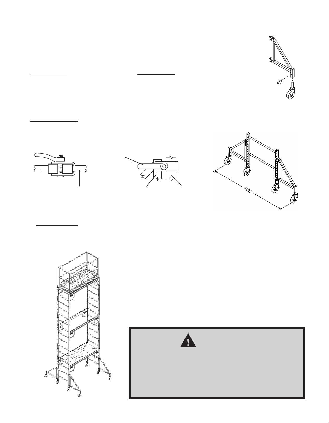
STEP TWO — Attach second side brace Bto both end frames Afollowing the same Step One
sequence.
STEP ONE — Attach side brace Bto two end frames Aby
following this sequence:
- Pull Saf-T-Lok®pin at each end of side brace to the
disengaged position. (see decal)
- While holding lock pin in disengaged position, place U-
Channel on each end of side brace Baround leg of end
frame Aat desired platform height.
- Release lock pin and be sure that pin fully engages into
hole in end frame leg.
- Push in and rotate Saf-T-Lok®counter clockwise until U-
shaped end clears the brace locking pin support bracket
as shown (LOCKED).
- To release, push in and rotate Saf-T-Lok®clockwise until
U-shaped end unseats from around the brace locking pin
support bracket as shown (UNLOCKED).
For proper assembly, your basic Pro-Jax Utility Scaffold
must be comprised of 13 individual parts (plus guard
rail panels when required).
Letter Part Qty.
A End Frame 2
B Side Brace 2
C Platform 1
D 5” Caster 4
E 2” Snap Pin 4
C
BA
B
A
E
D
ASSEMBLY INSTRUCTIONS
BUILDING A ONE FRAME HIGH SCAFFOLD
0202-0506
CTO
WARNING
L
Patents Pending
FAILURE TO FOLLOW THESE INSTRUCTIONS MAYRESULT IN
PLATFORM COLLAPSE CAUSING SERIOUS INJURY OR DEATH.
Do not use in this position
Work position
1. Check to be sure brace locking pin is fully
engagedinto frame leg.
2. Push in and rotate Saf-T-Lok
TM
counter
clockwiseuntil U-shaped end clears the
bracelocking pin support bracket as
shown(LOCKED).
3. To release, push in and rotate Saf-T-Lok
TM
clockwiseuntil U-shaped end unseats from
aroundthe brace locking pin support
bracketas shown (UNLOCKED).
© Bil-Jax, Inc. 2004

- Page 5 -
STEP THREE — Install platform C on side
braces Bso that platform is fully seated within
inner channel on top of side braces.
STEP FOUR — Rotate the platform clips
into the engaged position.
PUSH
DISENGAGED
ENGAGED
STEP SIX — (When recommended or required) When platform height exceeds 4 ft., guard
railing is recommended, but is not required. However, OSHA requires guard rails for all platforms
10 ft. or higher. Install each guard rail panel (2 required) into sockets in side braces Band secure
with lock pin. Be sure that guard rail gate swings inward over the platform.
GUARD RAIL SOCKET
IN SIDE BRACE
STEP FIVE — Install 4 casters Dinto legs of end frames Aand pin with snap pins E. Set brake
on each caster.
GUARD RAIL LEG
SIDE BRACE
PLATFORM
CHANNEL
• RecheckallsidebracelockpinsforfullengagementandthattheSaf-T-Lok
®
is in the locked
position before accessing platform.
• Recheckplatformtobesureitisproperlyseatedwithinsidebracechannelandtheplatform
clips are fully engaged before accessing.
• Whenaccessingplatform,climbovertopofendframeladder—do not swing around side
of end frame. Swinging around side of end frame will cause scaffold to tip over resulting
in serious injury or death.
WARNING
WARNING
Guard rail must be installed so that gate swings inward over platform. Failure to install guard
rail properly may result in serious injury or death!
Unique design allows the guard railing to stay at the platform level at all times.
Guardrailingdoesnottontheframebutinthesocketsontheplatformbrace.
GUARD RAIL PANEL
Panel Guard - 1 unit shown
(2 required per work level)

- Page 6 -
STACKING PRO-JAX®UNITS FOR ADDITIONAL HEIGHT
According to OSHA, all scaffolds must be restrained from tipping. This can be accomplished in one
of three ways:
1. For free standing scaffolds, the maximum platform height must not exceed 3 times* the narrowest
base dimension.
2. Guying the scaffold.
3. Tying the scaffold to a wall or other solid structure.
*Federal OSHA allows a maximum platform height of 4 times the narrowest base dimension. However, Bil-Jax recommends
that the maximum height be limited to 3 times the narrowest base dimension on all Pro-Jax utility scaffolds.
When additional platform height is required on a free standing scaffold, outriggers may be used to
extend the base dimensions. Bil-Jax has different size outriggers available for use with Pro-Jax
units. 18” wide outriggers are for use with two-frame high scaffolds and 24” wide outriggers are for
use with three-frame high scaffolds.
WARNING
WheneverPro-Jaxunitsarestacked,outriggersarerequired!Donotusea
Pro-Jax utility scaffold over 1 frame high without outriggers. Failure to use
outriggers will make scaffold more likely to tip over causing serious injury
or death!!
BUILDING A TWO FRAME HIGH SCAFFOLD
Top View
Outrigger Frame
Side View
Outrigger
Tighten
Securely
Frame
Leg
STEP THREE — Clamp outrigger to end frame at a 90°angle to the side brace.
Tighten clamp securely. Clamp must be ush against scaffold leg and casters must be
in contact with the surface.
STEP ONE — Erect the base
unit (one frame high scaffold) by
following the previous instruction.
STEP TWO — Install casters into all
four (4) outriggers and secure with snap pin
provided with each caster. Set caster brake.
If the platform height needed is between 6’ and 11’ 6”, it will be necessary to install 18” wide
outriggers and a second scaffold level prior to use.
STEP FOUR — Add
second scaffold level by
stacking end frame over
insert pins in top of base
unit end frames. Secure
in place with snap pins.
STEP FIVE — Install
side braces (minimum two),
platform, and guard railing at
desired height per the previous
instructions (Building a One
Frame High Scaffold).
- Page 7 -
STEP FOUR — Add additional scaffold end frames, side braces, platforms, and guard
railing (at each work level) per the previous instructions (Building a One Frame High Scaffold
and Building a Two Frame High Scaffold). Side braces should be evenly spaced in pairs
throughout the scaffold tower.
Top View Side View
Outrigger Frame
Tighten
Securely
Frame Leg
Outrigger
STEP THREE — Clamp outriggers to end frame with two piece clamp. Tighten clamp securely.
Clamp must be ush against scaffold leg and casters must be in contact with the surface.
If the platform height needed is over 11’ 6”, it will be necessary to install 24” wide
outriggers prior to stacking additional scaffold levels to the base unit.
WARNING
There must be a minimum of two side braces
installed in each scaffold level and evenly spaced
throughout the scaffold. Lack of adequate
bracing could cause scaffold to collapse with
serious injury or death to the user.
STEP ONE — Erect the base
unit (one frame high scaffold) by
following the previous instructions.
STEP TWO — Install casters into all four
(4) wide outriggers and secure with snap pin
provided with each caster. Set caster brake.
BUILDING A THREE FRAME HIGH SCAFFOLD
Table of contents
Other BilJax Industrial Equipment manuals


Popular Industrial Equipment manuals by other brands


Magnaflux
Magnaflux A-2030 Series installation guide

Sealey
Sealey YK20F.V3 instructions

Appleton
Appleton FSQC 30 A Installation & maintenance instructions

STS
STS M3-H Operator's manual

Renishaw
Renishaw RENGAGE OMP600 quick start guide

ChipBLASTER
ChipBLASTER STANDARD UNIT D30-80-1 Installation, operation and service manual

Honeywell
Honeywell VR9105V installation instructions

DEUTSCHE VAN RIETSCHOTEN & HOUWENS
DEUTSCHE VAN RIETSCHOTEN & HOUWENS R+H 200.551.01 Maintenance and operating manual

Viessmann
Viessmann 5071 Operation manual

TradeQuip
TradeQuip 1019T owner's manual

Condair
Condair AX Installation and operating manual

DecoRad
DecoRad Handmate UV 1800 user manual