STS M3-H User manual

Surface to Surface Inc. ®
Operators Manual
** M3-H **
USE IN CONJUNCTION WITH OEM MANUALS (ENCLOSED)
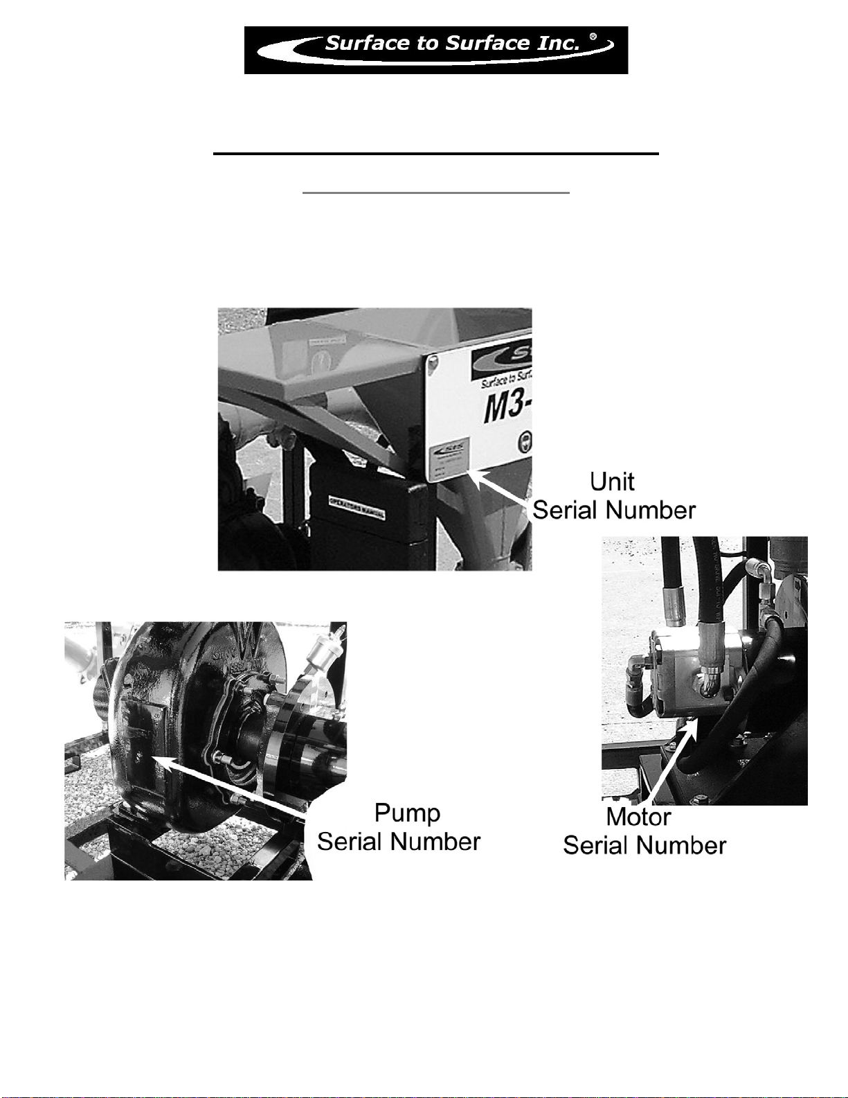
Unit Serial No. _______________
Hydraulic Motor
SNM2/11C106
Gorman-Rupp® Pump
STS-83A255 – Serial No. ________________
Control Valve
Serial No.__________________
Links relating to this Manual
www.stsmixers.com
www.grpumps.com
STS-112 Rev. 07/26/12 www.stsmixers.com
Dealer

2
This page left blank intentionally

3
TABLE OF
CONTENTS
PAGE
STS Inc Warranty………………………………………………………….. 6
Safety Statements………………………………………………...………… 7-10
Safety Markings……………………………………………………………. 11
Hydraulic Connections / Schematic…………………………...…………. 12
Main Working Components (Photo)……………………………………… 13
M3 Hose Connections ……………….……………………………………. 14
Introduction to the M3-H ……………….………….………….…………. 15
M3-H Foot Print (top view)………………………………………………… 16
M3-H General Data Sheet…………………………………………………. 17
Identifying Your Machine & Components………………………………. 18
SECTION II (Description, Care and Maintenance)
Hydraulic powered centrifugal pump.…….…………….………….…. 20-23
Filter shear system……………………………………………………. 24-25
Venturi mixing tee……………………………..………..……………. 26
Wash wand……………………………………………………...……. 27
Dry hopper with table & hopper valve…………………………..…… 28
Internal tank jets ……………………………………...……………… 29-30
Mixing Tee shut of valve (optional) ………….…….….….…….…… 31
SECTION III (Set-up and installation of unit in Detail)
Permanent mounting of unit…………………………...…………….. 33
Portable use of unit…………………….…………………….………. 33

4
TABLE OF
CONTENTS
PAGE
SECTION IV (Operating the M3 Unit.)
Site set-up and pre-check…………………………………………….. 35
Starting the hydraulic driven pump…………….….…....…….……… 36
Typical mixing operation……………………….……………………. 37
Typical transfer / off-loading operation……………………………… 38
Shutdown, cleanup & storage
Warm weather…………………………………….…………. 39
Cold/ freezing weather………………………………….…… 40
Prolonged periods of storage………………………………… 41
**Optional self-loading feature……………………………...………… 42
SECTION V (Trouble shooting)
Trouble Shooting the M3 ……………….…………………....……… 44-45
SECTION VI (Periodic Maintenance & Repair Information)
Maintenance Schedule…………………….….………………….…... 47
Centrifugal Trash Pump Seal Replacement………………………..… 48
Bolt torque Specifications…………………………………….……... 49
Notes…………………………………………………….…………… 50

5
TABLE OF
CONTENTS
PAGE
SECTION VII (OEM Repair / Information)
GR Centrifugal Pump Owner’s Manual……………………..………… 52-63
Gruvloc® Pipe Couplings ………….…….….….………………..…… 64-66
Sauer Danfoss Hydraulic motor …………..…….….….….….….……. 67-70
SECTION VIII (Parts Manual)
M3-H PARTS MANUAL…………………….……………….……. 71-73

6
Limited Warranty
United States and Canada
Surface to Surface Inc. or it’s subsidiary which last sold the product, warrants new products sold by it for use in the
United States and Canada to be, at the time of manufacture, free from defects in workmanship and materials. This
warranty covers for a period of Twelve (12) Months of operation from the date of delivery for initial use, whichever
comes first.
Exclusions and Additional Limitations
1. This warranty relates to the condition of the product at the time of manufacture and does not cover parts or
service as a result of:
(a) Normal wear and tear or required maintenance including, without limitation, adjustments or replacement of
components subject to wear and tear, such as belts, hoses, seals and/or packing, fuses, bulbs,
switches and ignition parts.
(b) Abuse including, without limitation, neglect, improper operation, misapplication, overloading, accident or
alterations not approved by Surface to Surface Inc.
(c) Lack of maintenance, including, without limitation, failure to inspect and maintain, improper repair, use of
“unapproved parts”, cracked engine heads and blocks unless caused by the failure of
an internally lubricated part or repair of engine valves, rings or guides.
2. The Company’s warranty does not apply to purchased components manufactured by others where separate
warranty is made by the manufacture of such components and will be applied as interpreted by
the supplier.
3. All claims under his warranty shall be submitted in writing by the distributor to the Company, which will be the
sole judge in determining the merits of the claim.
4. The company shall have the right to have all products or parts claimed to be defective returned to it and the
cost of shipping such items shall be borne by the distributor.
……………………………………………………………………………………
Warranty Registration Card
In order to help us provide complete service for our product, please complete this card and return it.
If not returned, all requests for warranty will be denied.
Print Name: …………………………………………………………………….….
Address: …………………………………………………………………………...
City: ……………………State/Province………………Zip/PC…………………...
Model No. ………………………….. Serial No. …………………………………
Date of Purchase ………………………… Dealer ………………………………..
Return to: Surface to Surface Inc.
5150 Forest Rd. RR#3
Watford, Ontario, Canada
N0M 2S0
01/14/08
7
M3-H
SAFETY STATEMENTS
Your personal safety and the safe operation of this unit are the concern of Surface to Surface Inc, and by
reading and understanding this manual and understanding the safety statements, you will decrease the risk of
personal and equipment damage.
Safety statements are listed here and throughout this manual to draw your attention to potential hazards that
may be encountered while operating this piece of equipment. While reading this manual, you will notice that
certain safety statements will relate directly to the operation, or maintenance of that particular part of the unit and
should be followed carefully. Decals on the unit also follow the same format as the warnings in this manual, and
therefore should be kept in good repair to alert the operator and others of the potential hazard.
The engine / motor manual also contains hazard warnings which pertain to the engine / motor and should
also be followed.
This safety alert symbol appears with most safety statements.
It means attention, become alert, your safety is involved!
Please read and abide by the message that follows the safety alert symbol.
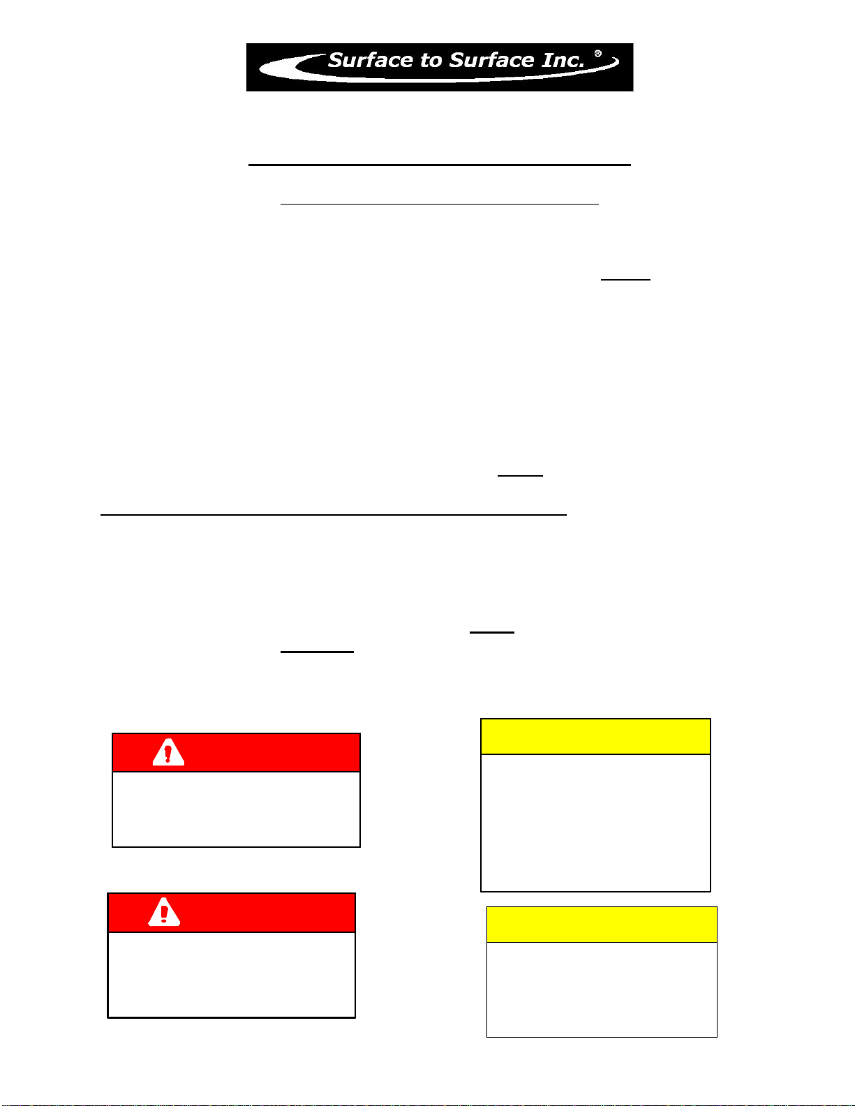
DANGER
WARNING CAUTION
CAUTION
Caution "without the safety alert symbol"
indicates an potentially hazardous
situtation that can cause damage to the,
machine, personal property and / or the
environment or cause the machine to
operate improperly.
Danger (the word "DANGER" is in white
letters with a red rectangle behind it)
indicates an imminently hazardous
situation, which, if not avoided, will
result in death or serious injury.
Danger is limited to the most extreme
situations.
Warning (the word "WARNING" is in black
letters with an orange rectangle behind it)
indicates an potentially hazardous
situation which, if not avoided, could
result in death or serious injury.
Caution (the word "CAUTION" is in black
letters with a yellow rectangle behind it)
indicates an potentially hazardous
situation which, if not avoided, may
result in minor or moderate injury.

8
M3-H
SAFETY STATEMENTS
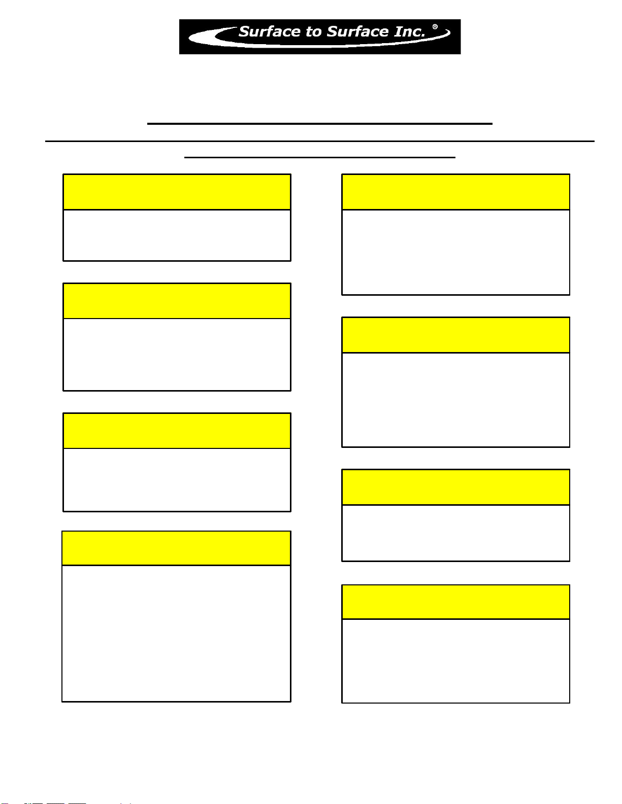
The following caution statements have been drawn from the instructions in this manual. They
have been assembled here for ready reference.
DANGER
IN AN EMERGENCY
DANGER
NEVER ATTE MPT REPAIRS
OR DISASSEMBLY
WARNING
NEVER USE B ODY PAR TS,
OR FOREIGN OBJE CTS
in an attempt to unplug or clean the
hopper valve or mixing tee.
Ser ious p er sona l inj ur y or
damage will result.
WARNING
Ser ious personal inj ury will result.
DO NOT REMOVE OR MOD IFY
SAF ETY COVERS OR GUARD S.
WARNING
while the unit is in operation.
Ser ious personal inj ury will result.
NE VER ATTEMPT TO REMO VE
OR CLEAN THE FILTER SHEAR
CAUTION
DO NOT POSITION
ANY PART OF YOUR BODY
over the hopper, valve,
or mixing t ee whil e clean ing.
rotate the flow control valve
lev er to the STOP position
to halt the pump , and fluid fl ow.
with out shut ting off t he hydr aulic
power source.
Ser ious personal inj ury will result.
CAUTION
WHEN THE UNIT
IS IN OPERATION,
the fluid i n the piping may reach
pressures up to 50 p.s.i.
9
M3-H
SAFETY STATEMENTS continued
The following caution statements have been drawn from the instructions in this manual. They
have been assembled here for ready reference.
CAUTION
TRAPPED FLUI D MAY BE P RESE NT
and will spill out when piping, hoses,
pump or fi lter shear are remov ed.
CAUTION
AVOID AL LOWIN G FOREIGN MATER IAL
into the Venturi Mixing Tee thru the
Hopper, by keeping the val ve closed
when not in use.
CAUTION
NE VER LEAVE LIQUI D IN THE
PUMP CASING, P IPING, OR HOSES
duri ng free z ing weather conditio ns,
as damage will result.
Foll ow ins tructio n for winteriz ing.
CAUTION
CAUTION
CA RE MU ST BE TAKE N WH EN
INS TALLIN G THE COUP LER GASKE TS.
If the gaskets are not pr operly lubricated
and installed, a leak may devel op.
CAUTION
IMP ROPER INSTALLATI ON OF THE
MEC HANI CAL or GREASE S EAL
will result in leak age and poss ible
damage to the seal. All maintenance,
ope rating and r e pair of this un it, mus t be
don e per t he inst ruction s in the opera tors
manual for safety and r eliabil ity.
CAUTION
WH EN TRANSFER RING FLUID
to the drill rig, fluid pressure may
reach or exceed 50 p.s.i.
CHE CK the drill r ig manufacturers
specifications regarding maximum i nlet
pre ssures allowe d for their pump.
BE FORE STARTING OR RESTARTING
the hydrau lic moto r and c entrifu gal pump,
make sur e any v alves installed on the
pump sucti on inlet line ar e open, and
the fluid level in the tank is above
the s uction line.
CAUTION
BEFORE STARTING TH E HYDRAULIC MOTOR,
BE SURE THE PUMP IS PRIMED!
Check the pump by slowly & carefully
opening the plug located on the top
of the centrifugal pump discharge elbow.
A visual inspection can be made if the fluid
escapes around the plug as it is loosened.
Remove the plug to v iew inside fluid level.
The centr ifugal pump seal WILL be
damaged if allowed t o cav itate or run dry.

10
M3-H
SAFETY STATEMENTS continued
The following caution statements have been drawn from the instructions in this manual. They
have been assembled here for ready reference.
CAUTION
The manu factur e r sho uld be consu lted
whe n cons idering alternativ e uses
for this piece of equipment.
This unit was de signe d for t he mix ing
and sheari ng of a dry additive, into a
liquid stre am.
Other uses may c reate unfores een sa fety
issues and personal inj ury r isk.
CAUTION
LIFTING LU GS OR THE L IFTING POINT(S)
identified and labelled on the skid
structure must be used in orde r to
safe ly lift and tra nspor t the unit.
WARNING
REFER TO THE SAFETY
STATEMENTS IN THE
OEM SUPPLIED MANUALS
AND
THIS MANUAL
REGARDING THESE
OPERATIONS.
11
M3-H
Safety Markings
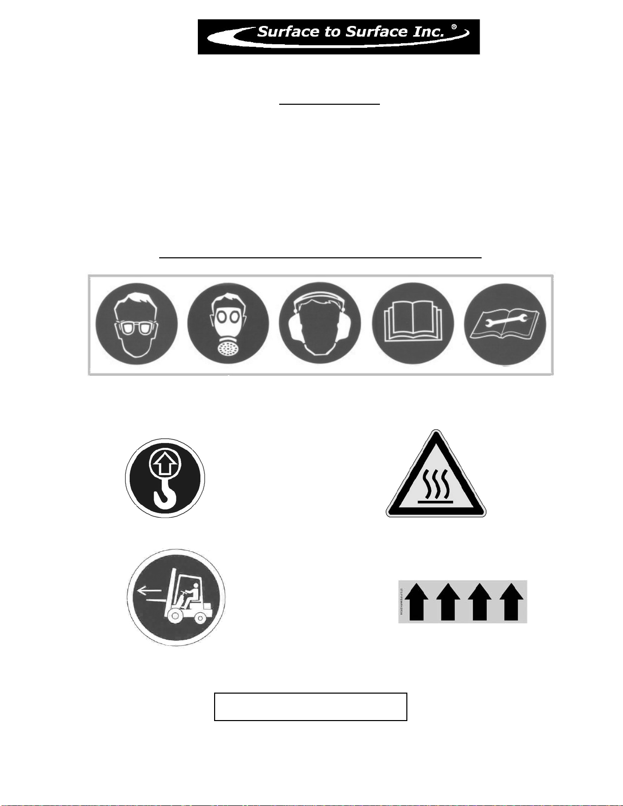
Hazard and warning markings have been placed at appropriate points on the unit. International symbols
have been used, in order to ensure universal understanding of the nature of the hazard. Please comply
with all warnings and markings to ensure safe use of the equipment. These include but are not limited to:
a) Lifting points b) Fluid flow direction
c) High temperature areas d) Personal Protection recommendations
e) Personal dangers f) Equipment dangers
g) Operating instructions
SOME EXAMPLES FOUND ON THE EQUIPMENT
Liftin
g
Point
Personal Protection
,
Read and understand O
p
erator’s manual and Maintenance manual
Hot Surface
Fluid Flow Direction
Maintenance Instructions
Liftin
g
Point
CLEAN FILTER DAILY

12
M3-H
These guidelines must be followed or warrant will be voided. Any variation needs
to be approved by Surface to Surface®.
SET-UP
Minimum Flow Rate: 10us gpm.
Maximum Flow Rate: 10.3us gpm.
Relief Setting: 2250psi.
Inlet Hose Size: 3/4" minimum
Outlet Hose Size: 3/4" minimum (
direct to reservoir
)
Caution:
As the hydraulic oil increases in temperature the hydraulic flow rate will rise
above your set rate of 10 - 10.3 g.p.m. of hydraulic flow. The hydraulic flow valve should
then be set back to the recommended flow rate of 10 – 10.3 g.p.m.
Specifications on hydraulic oil, operating temperature, and filtration can be found
further on in this manual, on the Sauer Danfoss hydraulic motor data sheets.
Any problems or question may be answered by calling Surface to Surface® at
(800) 567-0978 during normal business hours.
CF
EF
IN
1
2
3
4
5
6
7
8
9
01-20-06
RETURN LINES
PRESSURE LINES
CUSTOMER SUPPLIED
IN FLOW OUT FLOW
TO TANK
M3-H
10.3 usgpm. MAX.
Flow Meter

13

14

15
M3-H
Operators Manual
Congratulations on your acquisition of the time proven M3-H Mixing System. You have acquired the
fastest and most efficient mixing system manufactured for mixing Bentonite drilling slurry (mud). As a
manufacturer of HDD support equipment, we are well aware of the extreme conditions that HDD
equipment is exposed to on a daily basis. Surface To Surface Inc. strives to overcome these conditions,
with better design and manufacturing practices. Please feel free to call our toll free number
(1-800-567-0978) if you have any questions or concerns about your M-3.
Thank you, for choosing the M3 series mixer.
The M3 mixing unit was designed to mix dry or liquid drilling products with clean
water, into a slurry. The slurry is continually circulated through the mixing cycle until it
reaches the desired consistency. The operator can then transfer the final product to a holding
reservoir or directly to the drilling equipment.
The M3 mixing unit consists of a hydraulic powered centrifugal pump, filter/shear unit,
venturi mixing tee assembly, dry hopper with a table, a set of tank internal jets.
These components are all mounted on a frame type skid, built for lifting or solid mounting.
For ease of interpretation, looking at the mixing unit hopper straight on will be considered
looking at the front of the unit. Hence the other long side, will be the rear and the ends will be
right or left end.
RECORD OF OWNERSHIP:
• Unit Serial No. __________________________________________
• Motor Serial No.________________________________________
• Pump Serial No:_________________________________________
• Date Purchased/Leased:___________________________________
• Dealer Purchased/Leased From:_____________________________
• Special Custom Features:__________________________________
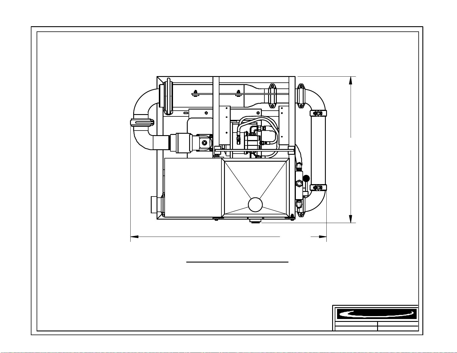
16
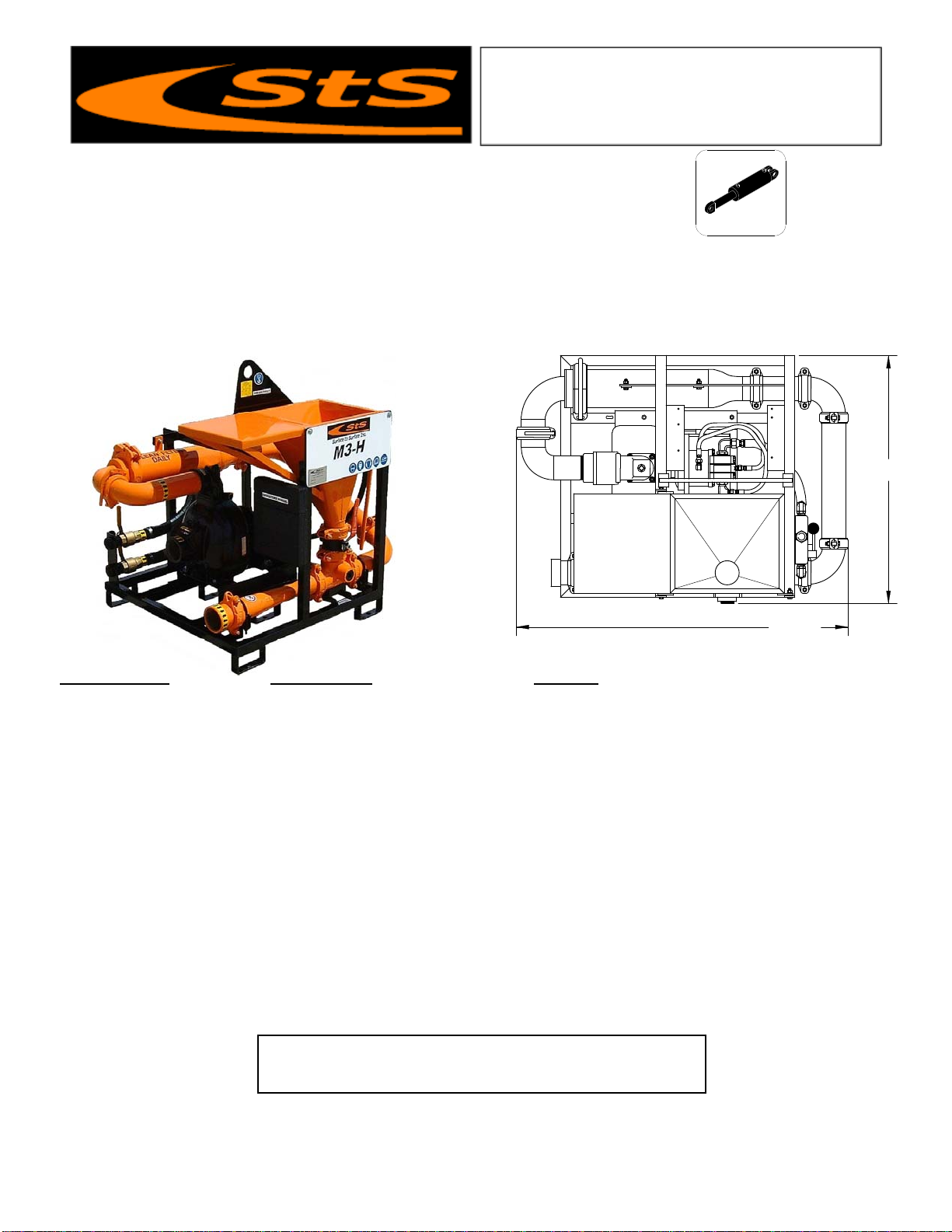
REV.
DATE.DWR. NUM.
* Due to our continuing product improvement, specifications are subject to change without notice. *
Surface to Surface Inc.
48 1/2"
36"
Height 35 1/2"
M3-H(GR) ( Hydraulic )
06 / 05 / 09
M3-H(GR)
DRY WEIGHT
550 lbs.
17
Features and Benefits M3-H Mixer
The M3-H universal mixer is designed around the time proven M series mixers of STS. Powered by the customer’s
own power source. A 10gpm. hydraulic motor drives a 3” centrifugal pump, making effective use of the proprietary 4
point mixing system. The M3-H can be used as a new installation or retrofitted into an existing system of tank(s). Since
the unit is connected by hoses and not hard pipe, the placement of the mixer verses the tank(s) is less restricted and a
configuration to suit the needs of the contractor is easier to achieve. The small size also makes it a portable,
independent unit that is easier to transport from site to site.
Specifications M3-H Mixer Benefits
Dimensions 36” W x 48½ ” L x 35½” H Small space saving footprint.
Weight 490 Lbs Light weight for easy transportation.
Hopper Height 35-1/2” High Waist high hopper reduces back strain.
Mixing System 3” Proprietary StS Mixing System Fast & efficient with high shearing ability.
Flow Valves Brass and Steel construction Withstand the abuse of daily operations
Skid Frame 1½” steel tube with fork pockets Built tough for the construction trade.
Hydraulic gear motor Requires 10gpm. @ 1800psi Use your own power source, no fumes in truck body
Hydraulic valve Variable speed controler Allow mixing at various speeds.
Hydraulic system Open loop circuit Simple, field repairable, less maintenance
Pump 3” Cast iron centrifugal trash pump Rugged & repairable for extended service life.
Pump Coupling Hyd. Motor direct to Bearing Block No expensive couplers or inserts to replace.
Vacuum Port 1½” NPT Inlet Draw Fluid into system without additional pump.
Pipe Couplers Bolt & Snap-groove type Fast cold weather draining of system.
Pressure Wand Hopper maintenance wand Removal of blockages caused by additive.
Internal Jet Guns TurboMix™ Eductor Nozzles Fast and effective rolling and mixing action.
A
lso available in Gas
(
M3-G
)
, Diesel
(
M3-D
)
or Electric
(
M3-E
)
models.
Surface to Surface Inc.
Universal 3” Mixer
Model M3-H
Surface to Surface Inc.
5150 Forest Road, R.R.#3, Watford, Ontario, N0M 2S0
Tel: 1-800-567-0978
Check our website for the latest products and specifications
www.stsmixers.com
06/08/09
Hydraulic
48 1/2"
36"
18
M3-H
Identifying Your Machine & Components
Location of Tags and PIN Plates

19
SECTION #II
Description, Care and Maintenance
20
M3-H
Description, Care and Maintenance
Hydraulic Powered Centrifugal Pump
Care and maintenance of the hydraulic motor and pump are covered in this manual and/or the
manufacturer operator’s manuals supplied and should be read and understood. We suggest the following
daily checks be carried out prior to using the system. Check the fluid level in YOUR hydraulic reservoir is
sufficient. Check the hydraulic filtering system is working properly. Check the pump seal grease cup is full
(see grease cup instructions Fig.5). Check that any water intake valve(s) are open and the reservoir tank has
sufficient liquid to supply the centrifugal pump.
The pump is mounted directly to a bearing block and the hydraulic motor, so there is no “drive
coupler” to check or maintain. The bearings in the bearing block are factory greased to provide constant
lubrication. The pump is the primary component that will see the most wear due to the nature of the
material it is handling therefore it will require regular checks, adjustments and maintenance.
There is a section of this manual dedicated to the pump itself and should be read and understood
which will help should any problems or concerns arise in the field.
The pump should never be allowed to start or run dry, as this WILL damage the internal pump seal (grease
seal) and render the unit inoperable until the seal is fixed.
To prime the pump or check to visually see if the pump is primed, slowly undo the plug (priming
port) on top of the pump discharge elbow (see Fig.4) and stop after about 3 turns. If the pump is primed,
fluid & air will escape from around the plug threads. This indicates that the pump housing is full, and the
plug can be tightened back up. If no fluid is escaping from around the threads, completely remove the plug.
Drill fluid or water can be poured into this opening to fill the pump cavity, and a visual of the fluid level
inside the pump can be made. The level should be approximately to the top of the pump housing.
Another way to prime the pump is to have the tank FULL of fluid, and standing off to the side of the
hopper, rotate the hopper valve SLOWLY to the open position. As the valve is opened, you will hear air
escaping followed by fluid, into the hopper itself. Close the valve as the fluid enters the hopper. This means
the fluid in the tank has filled the pump cavity of the pump and flowed from the outlet of the pump to the
remaining piping on the unit.
CAUTION
IMPROPER INSTALLATION OF THE
MECHANICAL or GREASE SEAL
will result in leakage and possible
damage to the seal. All maintenance,
operating and repair of this unit, must be
done per the instructions in the operators
manual for safety and reliability.
DANGER
IN AN EM ERGENCY
rotate the flow control valve
lev er to the STOP position
to h alt the pump, and fluid fl ow.
CAUTION
BEFORE STARTING THE HYDRAULIC MOTOR,
BE SURE THE PUMP IS PRIMED!
Check the pump by slowly & carefully
opening the plug located on the top
of the centr ifugal pump discharge elbow.
A v isual inspection c an be made if the fluid
escapes around the plug as it is loosened.
Remove the plug to v iew inside fluid level.
The centrifugal pump seal WILL be
damaged if allowed t o cav itate or run dr y.
DANGER
NEVER ATTE MPT REPAIRS
OR DISASSEMBLY
without shutting off the hydraulic
power source (customer supplied)
Serious personal inj ury will result.
Table of contents
Other STS Industrial Equipment manuals


