Part No. 540510 540510_-_HI
9
Starting the Engine
Read the engine manual before operation. A Honda engine manual is included within the machine packaging.
Never start the engine inside a building or other enclosed spaces.
Always check the engine oil level and ll when necessary before starting!
To start the engine on your BILLY GOAT® Auger:
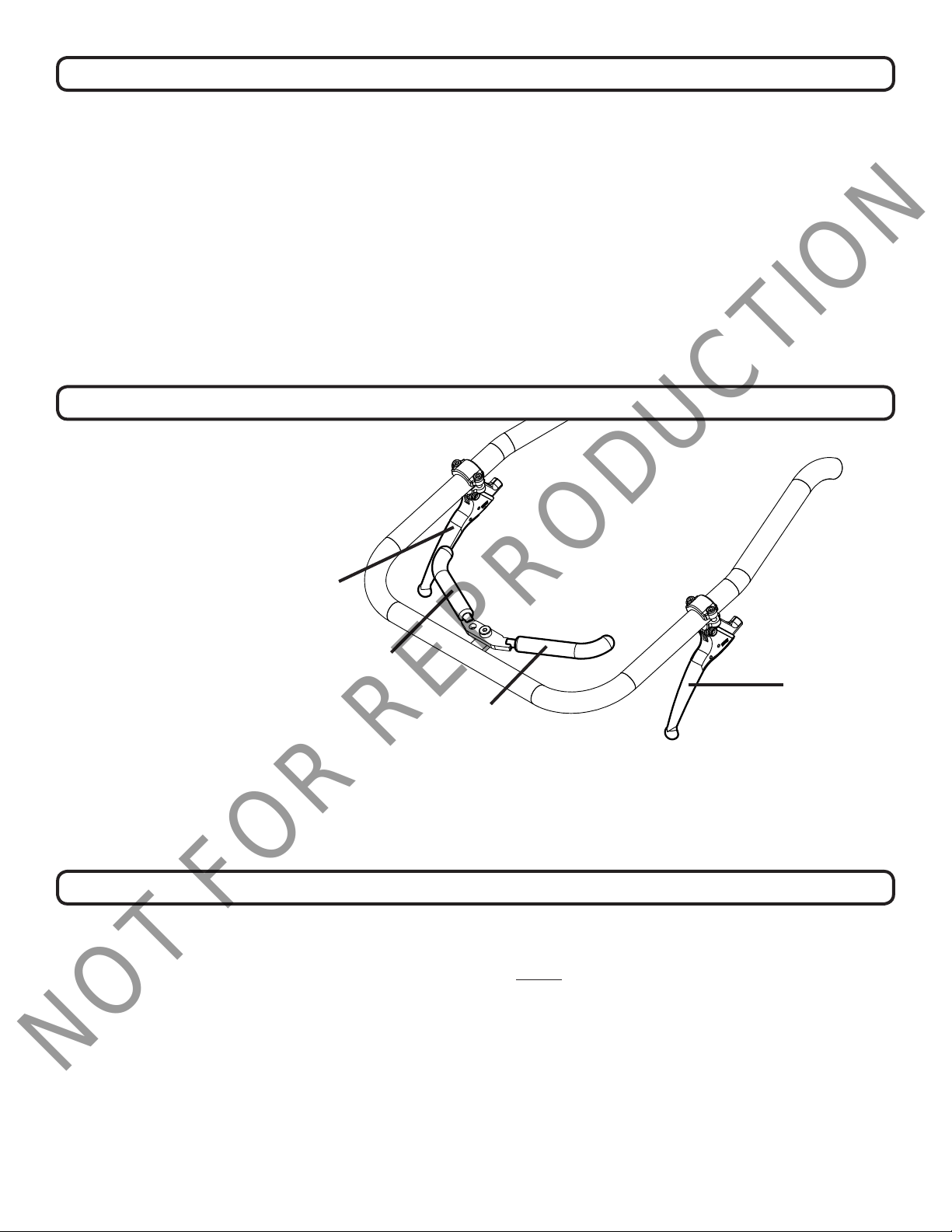
1. From the operator’s position, push the throttle lever completely forward to the “RUN” position.
2. Walk around to the front of the machine where the engine is located. Locate the engine’s choke lever. Pull out the
choke lever.
3. Pull the recoil handle to start the engine.
4. With the engine running, push the choke lever back into place.
5. Adjust the throttle lever to dictate the desired ground speed.
Note that in colder temperatures, there may be too much load on the engine to start it quickly. Locate the belt-drive dis-
engage chain on the left side of the machine (see decal P/N 540504 on the Instruction Labels page). Pull and lock the
chain to disengage the belt drive. Start the engine, then re-engage the chain after a few minutes.
Operation
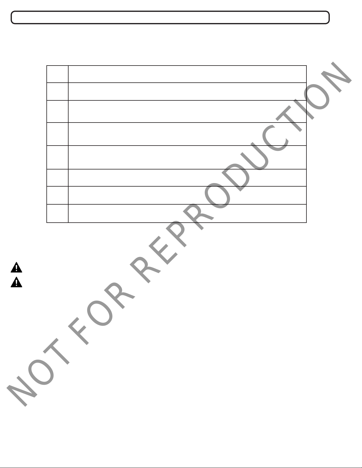
Pre-Operation Checklist
Before starting any project with your BILLY GOAT® Auger, check o each item in the Pre-Operation Checklist.
Read and ensure full understanding of the BILLY GOAT® Auger Owner’s Manual.
Call 811 in your state to ensure that all underground utilities are properly marked.
Wear protective clothing, safety glasses, gloves, hearing protection, and work
boots.Tie back long hair.
Check the level of engine oil and ll if necessary (See your engine manual for
engine maintenance procedures).
Check the level of hydraulic oil and ll if necessary (See Maintenance section for
hydraulic system maintenance procedures).
Check entire machine for loose ttings or hardware
Check all hydraulic hoses and ttings to ensure there are no leaks.
Ensure the auger bit ights, pilot bit, and teeth are clean and free of debris.