manuals.online logo
Brands
  1. Home
  2. •
  3. Brands
  4. •
  5. Bilstein
  6. •
  7. Automobile Accessories
  8. •
  9. Bilstein B8 5160 User guide

Bilstein B8 5160 User guide

E4-WM5-Y652A00
MOUNTING INSTRUCTION
created: 18.06.19 E4-WM5-Y652A00_0 page 1 of 9 latest revision:
IMPORTANT! READ THIS FIRST!
Installation of shock absorbers requires special tools and expert knowledge. Accordingly, installation of
all BILSTEIN products must be performed by a qualified suspension specialist.
When replacing other brands, BILSTEIN shock absorbers should always be installed as a set. All
BILSTEIN products must only be used for the specific, intended application as indicated in the application
guide. Any use of any BILSTEIN product other than for its intended use may result in serious
bodily injury or death.
Always use a chassis hoist for the installation of BILSTEIN products and make certain that the raised
vehicle is securely attached to the hoist and/or supported to prevent the vehicle from slipping, falling, or
moving during the installation process.
If you choose to install any BILSTEIN product without the necessary special tools, expertise or
chassis hoist, you may subject yourself to the risk of serious bodily injury or death. If you elect not
to use a chassis hoist, at least make sure the vehicle is on level ground, that all tires on the ground during
installation are blocked to prevent movement, that at least two tires are on the ground at all times, and that
adequately secured safety stands (jack stands) are used to support the chassis. NEVER get under the vehicle
until you have checked to make sure all of these steps are performed.
BILSTEIN suspension products are gas-filled and are highly pressurized.
Never place any BILSTEIN product in a vise or use a clamp on any BILSTEIN product.
Never apply heat near any BILSTEIN product.
Never attempt to open or repair any BILSTEIN product, in order to prevent serious bodily injury or
death.
Any attempt to misuse, misapply, modify, or tamper with any BILSTEIN suspension product voids any warranty
and may result in serious bodily injury or death.
While installing any BILSTEIN product:
Do not use impact tools for loosening or tightening fasteners, because this may destroy the screw
threads.
Self-locking fasteners must only be used once!
Reuse original equipment components only if they are in good condition, otherwise replace them with
new components.
Never remove the slight film of oil on the piston rod and seal.
All mounting fasteners for shocks and struts must be securely tightened before operating the vehicle.
After installing any BILSTEIN product:
The suspension caster and camber must be checked and/or adjusted to comply with the vehicle
manufacturer’s specifications.
The (load dependent) brake compensator and the anti-lock brake system must be checked and/or
reset to comply with the vehicle manufacturer’s specifications.
The headlight aim must be checked and adjusted.
E4-WM5-Y652A00
MOUNTING INSTRUCTION
created: 18.06.19 E4-WM5-Y652A00_0 page 2 of 9 latest revision:
BILSTEIN 5160 Series Reservoir Shock Absorbers are designed to fit your vehicle’s original shock
mounts with minor modifications. Modification for this product includes a lower mount relocation bracket
and a reservoir mount.
Installation Procedure:
A. Remove the existing front shocks from the vehicle following all procedures in the vehicle
manufacturer’s service manual.
B. A mount kit is included to allow the remote reservoir to be attached to the vehicle frame rail behind
the front bumper. This kit is depicted in Figure 1.
Item
Description
Qty.
1
RESERVOIR CLAMP
1
2
M8 x 1.25 x 18mm
COUNTERSUNK SCREW
2
3
M6 x 1 x 50mm SOCKET
HEAD CAP SCREW
1
4
M6 x 1 LOCK NUT
1
5
RESERVOIR MOUNT
PLATE
1
6
1/4"-20 x 1" HEX
SCREW
1
7
5/16”-18 x 1” HEX
SCREW
1
8
5/16"-18 x 1.25” HEX
SCREW
1
9
5/16" WASHER
1
10
3/8"-24 SERRATED
FLANGE NUT
1
11
1/4"-20 x 1.25" CAP
SCREW
1
12
1/4" WASHER
1
13
5/16"-18 SERRATED
FLANGE NUT
1
14
1/4"-20 THREADED
INSERT
1
15
5/16"-18 HEX
THREADED INSERT
1
16
ZIP TIE
1
17
OFFEST ZIP TIE
1
18
RUBBER STRIP
1
Figure 1
E4-WM5-Y652A00
MOUNTING INSTRUCTION
created: 18.06.19 E4-WM5-Y652A00_0 page 3 of 9 latest revision:
C. If you have access to a nutsert gun or pliers, that may be preferable to set the provided nutsert.
Otherwise, using the items in Figure 2, and a ½” box end wrench, arrange them as shown and turn
the ¼”-20 screw by hand until it is snug as shown in Figure 3.
Note that the screw will pass through the serrated flange nut without engaging the threads. The
serrations on the flange nut prevent the nutsert from rotating while setting it.
Figure 2
Figure 3
E4-WM5-Y652A00
MOUNTING INSTRUCTION
created: 18.06.19 E4-WM5-Y652A00_0 page 4 of 9 latest revision:
D. For the driver side, insert the nutsert into the hole shown in Figure 4. For the passenger side, insert
the nutsert into the hole shown in Figure 5.
E. While keeping the nutsert flange firm and parallel against the bumper support, tighten the screw using
a 7/16” box end wrench or socket. Turn it 2 rotations to set the nutsert. Tightening in ¼ turn
increments tends to work well.
F. Remove and discard the screw, washer and flange nut. The nutsert should now be rigidly fixed in the
hole.
G. Assemble the 5/16”-18 hex screw, 5/16” flat washer, a 9/16” boxed end wrench, the 3/8” serrated
flange nut and hex threaded insert the same way as in Figure 2.
H. For driver side, insert the nutsert into the hole shown in Figure 4. For the passenger side, insert the
nutsert into the hole shown in Figure 5.
I. While keeping the nutsert flange firm and parallel against the bumper support, tighten the screw using
a 1/2” box end wrench or socket. Turn it 2 rotations to set the nutsert. Tightening in ¼ turn increments
tends to work well.
J. Remove the screw and washer. Discard the washer and serrated flange nut. The nutsert should now
be rigidly fixed in the hole.
K. Assemble the reservoir bracket onto the mounting plate using the M8x1.25 countersunk screws as
shown in Figure 6. Torque the M8x1.25 countersunk screws to 10 lb•ft (13.6 N•m). Do not torque the
M6x1 cap screw at this time.
Figure 4 –Driver side
Figure 5 –Passenger side
Front of vehicle
Front of vehicle
1/4”-20
THREADED
INSERT
5/16”-18
HEX
INSERT
E4-WM5-Y652A00
MOUNTING INSTRUCTION
created: 18.06.19 E4-WM5-Y652A00_0 page 5 of 9 latest revision:
L. Install the plate and bracket assembly with the ¼”-20 x 1” screw in the upper nutsert. Rotate the
assembly and slide the reservoir into the bracket as shown in Figure 7. Rotate the bracket assembly
back up and install the 5/16”-18 x 1” screw in the bottom nutsert. Using a nonpermanent thread locker
is recommended.
M. Torque the two screws to 10 lb•ft (13.6 N•m).
N. Slide the reservoir down approximately where shown and torque the M6x1 socket head cap screw to
6 lb•ft (8 N•m).
Figure 6
Driver side
Passenger side
Front of vehicle
Front of vehicle
Figure 7 –Driver side
Figure 8 –Driver side
E4-WM5-Y652A00
MOUNTING INSTRUCTION
created: 18.06.19 E4-WM5-Y652A00_0 page 6 of 9 latest revision:
O. A mount kit is included to allow the lower shock mount to be offset away from the frame. This kit is
depicted in Figure 9.
P. Install the driver side shock in the original location with the top mount offsetting away from the vehicle
as shown in Figure 10.
OE BOLT
OE WASHER
SHOCK ABSORBER
HOUSING
HOUSING
WHEEL
Figure 9 –Lower mount offset bracket
Figure 10 –Drive side top
E4-WM5-Y652A00
MOUNTING INSTRUCTION
created: 18.06.19 E4-WM5-Y652A00_0 page 7 of 9 latest revision:
Q. Install the clevis from the mount kit in figure 9 using the M10 screw and nut. The position of the clevis
should allow the offset be towards the wheel. Torque down the fasteners to 31 lb•ft (42 N•m)
R. Place the spacer in between the flanges of the OE mount. Then position the shock’s lower mount
outside of the OE’s mount as shown in figure 11. Secure it with the M12 bolt and nut.
S. Torque the top and bottom mounting fasteners to factory specification.
T. Proceed onto the passenger side
Figure 11 –Driver side bottom mount
Wheel
E4-WM5-Y652A00
MOUNTING INSTRUCTION
created: 18.06.19 E4-WM5-Y652A00_0 page 8 of 9 latest revision:
U. Install the passenger side shock in the original location with the top mount offsetting away from the
vehicle as shown in Figure 12.
V. Install the clevis from the mount kit in figure 9 using the M8 screw and nut. The position of the clevis
should allow the offset be towards the wheel. Torque down fastener to 19 lb•ft (25 N•m).
W. Place the spacer in between the flanges of the OE mount. Then position the shock’s lower mount
outside of the OE’s mount as shown in figure 13. Secure it with the M12 bolt and nut.
Figure 12 –Passenger side top mount
WHEEL
OE WASHER
HOUSING
HOUSING
SHOCK ABSORBER
OE BOLT
Figure 13 –Passenger side bottom mount
Wheel
E4-WM5-Y652A00
MOUNTING INSTRUCTION
created: 18.06.19 E4-WM5-Y652A00_0 page 9 of 9 latest revision:
X. Torque the top and bottom mounting fasteners to factory specification.
Y. For the Driver side, route the hose as shown in Figure 14. Use the offset zip tie in the hole shown and
route the hose behind the fender lining and brake line. Apply the rubber strip where shown.
Z. For the Passenger side, route the hose as shown in Figures 15 and 16. Carefully remove the zip ties
holding the electrical cable shown. Route the hose behind these cables. If the factory zips tie are in
good condition, reuse them. If not, replace them with the supplied zip ties. Apply the rubber strip
where shown.
AA. Carefully check for any possible interference between the reservoirs/hoses and any other
components on the vehicle. The reservoir mounting location depicted is appropriate for most vehicles
for which this kit is intended, however, some wheel/tire and/or lift kit combinations and/or other
vehicle modifications may create interference problems. It is the responsibility of the installer to
determine if the reservoirs are mounted appropriately and if there is any potential for interference.
BB. If no potential interference is found, the installation is complete.
Front of vehicle
Figure 14 –Driver side
OFFSET ZIP TIE
Figure 15 –Passenger side
Figure 16 –Passenger side
APPLY RUBBER
STRIP HERE
APPLY
RUBBER
STRIP
HERE
REMOVE
THIS ZIP
TIE

This manual suits for next models

5

Other Bilstein Automobile Accessories manuals
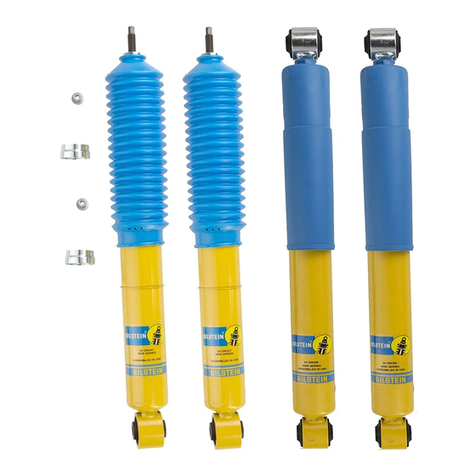
Bilstein 25-187632 User guide

Bilstein

Bilstein 25-187632 User guide

Bilstein E4-WM5-Y267A00 User guide

Bilstein

Bilstein E4-WM5-Y267A00 User guide

Bilstein B8 8100 User guide

Bilstein

Bilstein B8 8100 User guide

Bilstein E4-WM5-Y715A00 User guide

Bilstein

Bilstein E4-WM5-Y715A00 User guide

Bilstein E4-WM5-Y558A00 User guide

Bilstein

Bilstein E4-WM5-Y558A00 User guide

Bilstein 22-310408 User guide

Bilstein

Bilstein 22-310408 User guide

Bilstein E4-WM5-Y723A00 User guide

Bilstein

Bilstein E4-WM5-Y723A00 User guide

Bilstein E4-WM5-Y116A00 User guide

Bilstein

Bilstein E4-WM5-Y116A00 User guide

Bilstein Blue Print ADC44288 User manual

Bilstein

Bilstein Blue Print ADC44288 User manual

Bilstein B8 5100 User guide

Bilstein

Bilstein B8 5100 User guide

Bilstein E4-WM5-Y479A00 User guide

Bilstein

Bilstein E4-WM5-Y479A00 User guide

Bilstein B8 8100 User guide

Bilstein

Bilstein B8 8100 User guide

Bilstein E4-WM5-Y722A00 User guide

Bilstein

Bilstein E4-WM5-Y722A00 User guide

Bilstein B8 5100 User guide

Bilstein

Bilstein B8 5100 User guide

Bilstein 24-266659 User guide

Bilstein

Bilstein 24-266659 User guide

Bilstein E4-WM5-Y592A00 User guide

Bilstein

Bilstein E4-WM5-Y592A00 User guide

Bilstein E4-WM5-Y711A00 User guide

Bilstein

Bilstein E4-WM5-Y711A00 User guide

Bilstein 4600 Series User guide

Bilstein

Bilstein 4600 Series User guide
Popular Automobile Accessories manuals by other brands
Dakota Digital VFD3-73F-PU manual

Dakota Digital

Dakota Digital VFD3-73F-PU manual

Whispbar K638W Fitting Instructions for Basic Carrier

Whispbar

Whispbar K638W Fitting Instructions for Basic Carrier

EUFAB 11234 manual

EUFAB

EUFAB 11234 manual

Expedition One HI-LIFT/PULL PAL GEN 2 installation guide

Expedition One

Expedition One HI-LIFT/PULL PAL GEN 2 installation guide

Menabo SHUTTLE Fitting instructions

Menabo

Menabo SHUTTLE Fitting instructions

Tronic TCA 3 A1 operating instructions

Tronic

Tronic TCA 3 A1 operating instructions

Cruz N30-140 Assembly instructions

Cruz

Cruz N30-140 Assembly instructions

ATD Tools ATD-5200 owner's manual

ATD Tools

ATD Tools ATD-5200 owner's manual

Bestop TREKTOP NX GLIDE installation instructions

Bestop

Bestop TREKTOP NX GLIDE installation instructions

Thule 2081 parts list

Thule

Thule 2081 parts list

Venturi mini user guide

Venturi

Venturi mini user guide

TrailFX A7003S/B installation instructions

TrailFX

TrailFX A7003S/B installation instructions

Menabo 000136400000 Fitting instructions

Menabo

Menabo 000136400000 Fitting instructions

Dakota Digital MCL-2011(-R) manual

Dakota Digital

Dakota Digital MCL-2011(-R) manual

HUSKY LINERS 4707 installation guide

HUSKY LINERS

HUSKY LINERS 4707 installation guide

TBC DPI1K user guide

TBC

TBC DPI1K user guide

Berger & Schroter ProfiTech 20121 Assembly and operating instructions

Berger & Schroter

Berger & Schroter ProfiTech 20121 Assembly and operating instructions

Gamber Johnson TrimLine 7300-0600-03 user guide

Gamber Johnson

Gamber Johnson TrimLine 7300-0600-03 user guide

manuals.online logo
manuals.online logoBrands
  • About & Mission
  • Contact us
  • Privacy Policy
  • Terms and Conditions

Copyright 2025 Manuals.Online. All Rights Reserved.