manuals.online logo
Brands
  1. Home
  2. •
  3. Brands
  4. •
  5. Bilstein
  6. •
  7. Automobile Accessories
  8. •
  9. Bilstein B8 8100 User guide

Bilstein B8 8100 User guide

E4-WM5-Y631A00
MOUNTING INSTRUCTION
created: 12.06.19 E4-WM5-Y631A00_0 Page 1 of 23 latest revision:
This instruction is for both left front (driver) 25-287806 and right front (passenger) 25-287813
B8 8100 shocks. A bill of materials (BOM) of the included mounting parts kits is shown on the
next page.
IMPORTANT! READ THIS FIRST!
Installation of shock absorbers requires special tools and expert knowledge. Accordingly, installation of all BILSTEIN
products must be performed by a qualified suspension specialist.
When replacing other brands, BILSTEIN shock absorbers should always be installed as a set. All BILSTEIN products
must only be used for the specific, intended application as indicated in the application guide. Any use of any BILSTEIN
product other than for its intended use may result in serious bodily injury or death.
Always use a chassis hoist for the installation of BILSTEIN products and make certain that the raised vehicle is securely
attached to the hoist and/or supported to prevent the vehicle from slipping, falling, or moving during the installation
process.
If you choose to install any BILSTEIN product without the necessary special tools, expertise or chassis hoist, you
may subject yourself to the risk of serious bodily injury or death. If you elect not to use a chassis hoist, at least make
sure the vehicle is on level ground, that all tires on the ground during installation are blocked to prevent movement, that at least
two tires are on the ground at all times, and that adequately secured safety stands (jack stands) are used to support the chassis.
NEVER get under the vehicle until you have checked to make sure all of these steps are performed.
BILSTEIN suspension products are gas-filled and are highly pressurized.
Never place any BILSTEIN product in a vise or use a clamp on any BILSTEIN product.
Never apply heat near any BILSTEIN product.
Never attempt to open or repair any BILSTEIN product, in order to prevent serious bodily injury or death.
Any attempt to misuse, misapply, modify, or tamper with any BILSTEIN suspension product voids any warranty and may result
in serious bodily injury or death.
While installing any BILSTEIN product:
Do not use impact tools for loosening or tightening fasteners, because this may destroy the screw threads.
Self-locking fasteners must only be used once!
Reuse original equipment components only if they are in good condition, otherwise replace them with new components.
Never remove the slight film of oil on the piston rod and seal.
All mounting fasteners for shocks and struts must be securely tightened before the vehicle is operated.
After installing any BILSTEIN product:
The suspension caster and camber must be checked and/or adjusted to comply with the vehicle manufacturer’s
specifications.
The (load dependent) brake compensator and the anti-lock brake system must be checked and/or reset to comply with
the vehicle manufacturer’s specifications.
The headlight aim must be checked and adjusted.
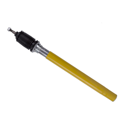
B8 8100 bypass shocks feature a proprietary BILSTEIN zinc plated finish. This finish must be serviced in order to
maintain its luster. Particularly in moist climates, a protective coating, such as a wax or lubricating oil should be
periodically applied to prevent tarnishing. This finish is not covered under warranty.
It is normal to hear a slight audible clicking noise during compression and rebound strokes in the B8 8100 bypass
shocks, most notably during low velocity events. This is due to the internal check pistons opening and closing to
create the externally adjustable compression and rebound zones.
E4-WM5-Y631A00
MOUNTING INSTRUCTION
created: 12.06.19 E4-WM5-Y631A00_0 Page 2 of 23 latest revision:
Figure 1 –Reservoir Mount Kit for Vehicle Left Side (25-287806)
E4-WM5-Y631A00
MOUNTING INSTRUCTION
created: 12.06.19 E4-WM5-Y631A00_0 Page 3 of 23 latest revision:
Figure 2 –Reservoir Mount Kit for Vehicle Right Side (25-287813)
E4-WM5-Y631A00
MOUNTING INSTRUCTION
created: 12.06.19 E4-WM5-Y631A00_0 Page 4 of 23 latest revision:
Bill of Materials
Item #
Description
Qty. in 25-287806
Qty. in 25-287813
1
Reservoir Bracket Plate
1
1
2
Reservoir Clamp; Ø60mm
1
1
3
Flat Head Screw; M8x1.25; L=18
2
2
4
Flange Head Cap Screw, 1/4"-20 x 1"
1
1
5
Flange Head Cap Screw, 5/16"-18 x 1"
1
1
6
Threaded Insert, 1/4"-20 Internal Thread
1
1
7
Threaded Insert, 5/16"-18, Internal, Hex
1
1
8
Socket Head Cap Screw; M6x1; L=50
1
1
9
Nylock; M6x1
1
1
10
Hex Head Cap Screw, 1/4"-20 x 1.25"
1
1
11
Washer, 1/4" ID x 3/4" OD, Grade 9 Steel
1
1
12
Serrated Flange Nut, 5/16"-18
1
1
13
Hex Head Cap Screw, 5/16"-18 x 1.25"
1
1
14
Washer, 5/16"
1
1
15
Serrated Flange Nut, 3/8"-24
1
1
16
Mount Bracket, Reservoir Hose, JL, Left
1
-
17
Socket Head Cap Screw, SS, M8x1.25, L=20
1
-
18
Serrated Flange Nut; M8x1.25
1
2
19
Loop Clamp, Hose, 7/8" Dia.
1
1
20
Button Head Screw; M8x1.25; L=18; SS
1
2
21
Rubber Strip
1
1
22
Mount Bracket, Reservoir Hose, JL, Right
-
1
E4-WM5-Y631A00
MOUNTING INSTRUCTION
created: 12.06.19 E4-WM5-Y631A00_0 Page 5 of 23 latest revision:
B8 8100 bypass shock installation procedure:
B8 8100 bypass shocks are corner specific. The step by step procedure is shown with pictures of both sides.
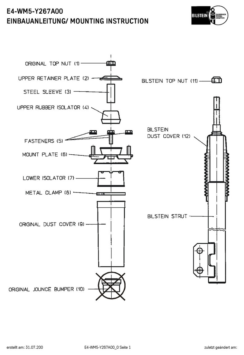
See page 22 for the end result.
*Installation of B8 8100 bypass shocks requires the use of wheels with a maximum of 4.5” backspacing to ensure
clearance between the tire and the shocks.*
A. Remove the existing shocks from the vehicle following all procedures in the vehicle manufacture’s service manual.
Inspect the OE upper bolts/washers for any excessive wear. If damage or excessive wear is present in any of these
components, purchase the required replacement OE components.
B. A mount kit is included to allow the remote reservoir to be attached to the vehicle frame rail behind the front bumper.
This kit is depicted in Figure 1 for the left side shock (25-287806) and Figure 2 for the right side shock (25-287813).
C. If you have access to a threaded insert gun or pliers, that may be preferable to set the provided threaded inserts
(BOM item #6 & #7). Otherwise, using the items in Figure 3, and a ½” box end wrench, arrange them as shown and
turn the ¼”-20 screw (BOM item #10) by hand until it is snug as shown in Figure 4.
Note that the screw will pass through the serrated flange nut without engaging the threads. The serrations on
the flange nut prevent the threaded insert from rotating while setting it.
Figure 3
E4-WM5-Y631A00
MOUNTING INSTRUCTION
created: 12.06.19 E4-WM5-Y631A00_0 Page 6 of 23 latest revision:
Figure 4
D. For the left side, insert the threaded insert (BOM item #6) into the hole shown in Figure 5. For the right side, insert the
threaded insert (BOM item #6) into the hole shown in Figure 6.
Figure 5 –Vehicle Left Side Figure 6 –Vehicle Right Side
E. While keeping the threaded insert (BOM item #6) flange firm and parallel against the bumper support, tighten the
screw (BOM item #10) using a 7/16” box end wrench or socket. Turn it 2 rotations to set the threaded insert.
Tightening in ¼ turn increments tends to work well.
F. Remove and discard the screw (BOM item #10), washer (BOM item #11), and serrated flange nut (BOM item #12).
The threaded insert (BOM item #6) should now be rigidly fixed in the hole.
G. Assemble the 5/16”-18 hex screw (BOM item #13), 5/16” flat washer (BOM item #14), a 9/16” boxed end wrench, the
3/8” serrated flange nut (BOM item #15) and hex threaded insert (BOM item #7) the same way shown in Figure 3.
1/4”-20
THREADED
INSERT
5/16”-18
HEX
INSERT
E4-WM5-Y631A00
MOUNTING INSTRUCTION
created: 12.06.19 E4-WM5-Y631A00_0 Page 7 of 23 latest revision:
H. For the left side, insert the hex threaded insert (BOM item #7) into the hole shown in Figure 5. For the right side, insert
the hex threaded insert (BOM item #7) into the hole shown in Figure 6.
I. While keeping the hex threaded insert (BOM item #7) flange firm and parallel against the bumper support, tighten the
screw (BOM item #13) using a 1/2” box end wrench or socket. Turn it 2 rotations to set the hex threaded insert (BOM
item #7). Tightening in ¼ turn increments tends to work well.
J. Remove and discard the screw (BOM item #13), washer (BOM item #14), and serrated flange nut (BOM item #15).
The hex threaded insert (BOM item #7) should now be rigidly fixed in the hole.
K. Prepare the reservoir mount assembly by applying non-permanent thread locker to two Flat Head Screws (BOM item
#3). Mount the Reservoir Clamp (BOM item #2) to the Bracket Plate (BOM item #1) using the two Flat Head Screws
(BOM item #3) as shown in Figures 7 and 8. Tighten the Flat Head Screws (BOM item #3) using a 5mm hex.
Torque both screws to 16 ft-lb (22 Nm).
L. Place the Nylock (BOM item #9) in the slot of the Reservoir Clamp (BOM item #2) as shown in Figures 7 and 8. Then
insert the Socket Head Cap Screw (BOM item #8) into the hole in the Reservoir Clamp (BOM item #2), threading it
into the Nylock (BOM item #9) as shown in Figures 7 and 8. Using a 5mm Hex, Tighten the Socket Head Cap Screw
(BOM item #8) only a few turns, leaving it loose enough so the reservoir can be installed a following step of these
instructions.
Figures 7 - Vehicle Left Side Assembly
E4-WM5-Y631A00
MOUNTING INSTRUCTION
created: 12.06.19 E4-WM5-Y631A00_0 Page 8 of 23 latest revision:
Figures 8 - Vehicle Right Side Assembly
Left Side Reservoir Hose Mount Bracket
M. Locate the hole in the front side of the left spring bucket shown in figure 9. Using a M8x1.25 Socket Head Cap Screw
(BOM item #17), and a M8x1.25 Serrated Flange Nut (BOM item #18), attach the Left Reservoir Hose Mount Bracket
(BOM item #16) to the spring bucket and orient as shown in figures 10 and 11.
Torque the screw to 16 ft-lb (22 Nm).
E4-WM5-Y631A00
MOUNTING INSTRUCTION
created: 12.06.19 E4-WM5-Y631A00_0 Page 9 of 23 latest revision:
Figure 9 –Vehicle Left Side Spring Bucket
Figure 10 –Vehicle Left Side Reservoir Hose Mount Bracket
E4-WM5-Y631A00
MOUNTING INSTRUCTION
created: 12.06.19 E4-WM5-Y631A00_0 Page 10 of 23 latest revision:
Figure 11 –Vehicle Left Side Serrated Flange Nut Installed
Right Side Reservoir Hose Mount Bracket
N. Locate the hole in the front side of the right spring bucket shown in figure 12. Using a M8x1.25 Button Head Screw
(BOM item #20), and a M8x1.25 Serrated Flange Nut (BOM item #18), attach the Right Reservoir Hose Mount
Bracket (BOM item #22) to the spring bucket and orient as shown in figures 13 and 14.
Torque the screw to 16 ft-lb (22 Nm).
E4-WM5-Y631A00
MOUNTING INSTRUCTION
created: 12.06.19 E4-WM5-Y631A00_0 Page 11 of 23 latest revision:
Figure 12 –Vehicle Right Side Spring Bucket
Figure 13 –Vehicle Right Side Hose Bracket
E4-WM5-Y631A00
MOUNTING INSTRUCTION
created: 12.06.19 E4-WM5-Y631A00_0 Page 12 of 23 latest revision:
Figure 14 –Vehicle Right Side Serrated Flange Nut Installed
Shock Upper Mount Installation
O. Install the shock’s upper mount using the supplied 30mm Spacer, and OE upper bolt/washer as shown in Figures 15
through 18. Do not tighten at this time.
E4-WM5-Y631A00
MOUNTING INSTRUCTION
created: 12.06.19 E4-WM5-Y631A00_0 Page 13 of 23 latest revision:
Figure 15 –Vehicle Left Side Upper Mount Assembly Diagram
Figure 16 –Vehicle Left Side Upper Mount
WHEEL
OE BOLT
OE WASHER
CHASSIS
CHASSIS
30mm SPACER
SHOCK
ABSORBER
E4-WM5-Y631A00
MOUNTING INSTRUCTION
created: 12.06.19 E4-WM5-Y631A00_0 Page 14 of 23 latest revision:
Figure 17 –Vehicle Right Side Upper Mount Assembly Diagram
Figure 18 –Vehicle Right Side Upper Mount
30mm SPACER
CHASSIS
SHOCK
ABSORBER
CHASSIS
OE WASHER
OE BOLT
WHEEL
E4-WM5-Y631A00
MOUNTING INSTRUCTION
created: 12.06.19 E4-WM5-Y631A00_0 Page 15 of 23 latest revision:
Shock Lower Mount Installation
P. A mount kit is included to allow the lower shock mount to be offset away from the frame. This kit is depicted in Figure
19.
Figure 19 –Lower Mount Offset Bracket
Q. Install the Mount Clevis (BOM item #23) using the M10x1.5 Flat Head Screw (BOM item #26) and M10x1.5 Nut (BOM
Item #28) for the left side of the vehicle. For installation on the right side of the vehicle, use the M8x1.25 Flat Head
Screw (BOM item #25) and M8x1.25 Nut (BOM item #27).
Torque the screw to 31 ft-lb (42 Nm).
E4-WM5-Y631A00
MOUNTING INSTRUCTION
created: 12.06.19 E4-WM5-Y631A00_0 Page 16 of 23 latest revision:
R. Place the Spacer (BOM item #24) between the flanges of the OE mount. Positon the shock’s lower mount between
the outside flange of the OE mount and the clevis. Make sure the shocks lower mount is installed angling the shock
toward the back of the vehicle and inward toward the chassis as shown in Figures 20 and 21. Do not tighten at this
time.
Figure 20 –Vehicle Left Side Lower Mount
Figure 21 –Vehicle Right Side Lower Mount
E4-WM5-Y631A00
MOUNTING INSTRUCTION
created: 12.06.19 E4-WM5-Y631A00_0 Page 17 of 23 latest revision:
Reservoir Mounting
S. Apply non-permanent thread locker to the 5/16”-18 X 1” Flange Head Cap Screw (BOM item #5) and install the
reservoir mount assembly with the screw in the bottom threaded insert. Leave the screw loose for now. Rotate the
assembly toward the rear of the vehicle and slide the reservoir into the clamp as shown in Figures 22 through 25.
Figure 22 - Left Front Mount Assembly Tilted Figure 23 –Right Front Mount Assembly Tilted
Figure 24 –Left Front Reservoir Slide Into Mount Figure 25 –Right Front Reservoir Slide Into Mount
E4-WM5-Y631A00
MOUNTING INSTRUCTION
created: 12.06.19 E4-WM5-Y631A00_0 Page 18 of 23 latest revision:
T. Rotate the reservoir mount assembly back to vertical. Apply non-permanent thread locker to the 1/4”-20 x 1” Flange
Head Cap Screw (BOM item #4) and install it in the upper threaded insert.
Torque both screws 10 ft-lb (13.6 Nm).
U. Position the end of the reservoir tube approximately 40mm below the bottom side of the clamp as shown in Figure 26.
With the reservoir hose exiting straight toward the back of the vehicle, tighten the Socket Head Cap Screw in the
Reservoir Clamp so the reservoir does not move.
Figure 26 –Reservoir Height
40mm
E4-WM5-Y631A00
MOUNTING INSTRUCTION
created: 12.06.19 E4-WM5-Y631A00_0 Page 19 of 23 latest revision:
Apply Rubber Protective Strip
V. To protect the reservoir hose from abrading on the chassis, a rubber strip (BOM item #21) should be applied to the
chassis body mount in the locations shown in Figure 27 on the left side of the vehicle and 28 on the right side of the
vehicle. To apply the strip on the curved surface, either cut the adhesive backed side of the angled Rubber Strip
(BOM item #21) to allow for flexibility around the curve, or cut it in half, and apply to either side of the curve.
Figure 27 –Left Side Location for Rubber Strip Figure 28 –Right Side Location for Rubber Strip
Left Side Reservoir Hose Mounting
W. Spread the Loop Clamp (BOM item #19) enough to wrap it around the left side reservoir hose. Apply non-permanent
thread locker to the M8x1.25 Button head Screw (BOM item #20), and secure the Loop Clamp (BOM item #19) to the
Left Reservoir Hose Mount Bracket (BOM item #16) as shown in Figures 29 and 30.The Loop Clamp (BOM item
#19) should be pointed toward the front of the vehicle.
Torque the screw to 16 ft-lb (22 Nm).
Apply Rubber Strip
Apply Rubber Strip
E4-WM5-Y631A00
MOUNTING INSTRUCTION
created: 12.06.19 E4-WM5-Y631A00_0 Page 20 of 23 latest revision:
Figure 29 –Left Reservoir Hose Installed Figure 30 –Left Reservoir Hose Installed (Side View)
Right Side Reservoir Hose Mounting
X. Spread the Loop Clamp (BOM item #19) enough to wrap it around the right side reservoir hose. Apply non-
permanent thread locker to the M8x1.25 Button head Screw (BOM item #20), and using a M8x1.25 Serrated Flange
Nut (BOM item #18), secure the Loop Clamp (BOM item #19) to the Reservoir Hose Mount Bracket (BOM item #22)
on the right side as shown in Figure 31.The Loop Clamp (BOM item #19) should be pointing toward the outside of
the vehicle.
Torque the screw to 16 ft-lb (22 Nm).
Figure 31 –Right Reservoir Hose Installed

Other manuals for B8 8100

1

Other Bilstein Automobile Accessories manuals

Bilstein Blue Print ADC44288 User manual

Bilstein

Bilstein Blue Print ADC44288 User manual

Bilstein E4-WM5-Y558A00 User guide

Bilstein

Bilstein E4-WM5-Y558A00 User guide

Bilstein E4-WM5-Y715A00 User guide

Bilstein

Bilstein E4-WM5-Y715A00 User guide

Bilstein E4-WM5-Y116A00 User guide

Bilstein

Bilstein E4-WM5-Y116A00 User guide

Bilstein B8 5160 User guide

Bilstein

Bilstein B8 5160 User guide

Bilstein E4-WM5-Y722A00 User guide

Bilstein

Bilstein E4-WM5-Y722A00 User guide

Bilstein E4-WM5-Y267A00 User guide

Bilstein

Bilstein E4-WM5-Y267A00 User guide

Bilstein B8 5100 User guide

Bilstein

Bilstein B8 5100 User guide

Bilstein E4-WM5-Y711A00 User guide

Bilstein

Bilstein E4-WM5-Y711A00 User guide

Bilstein B8 8100 User guide

Bilstein

Bilstein B8 8100 User guide

Bilstein 25-187632 User guide

Bilstein

Bilstein 25-187632 User guide

Bilstein 22-310408 User guide

Bilstein

Bilstein 22-310408 User guide

Bilstein 4600 Series User guide

Bilstein

Bilstein 4600 Series User guide

Bilstein E4-WM5-Y723A00 User guide

Bilstein

Bilstein E4-WM5-Y723A00 User guide

Bilstein B8 5100 User guide

Bilstein

Bilstein B8 5100 User guide

Bilstein E4-WM5-Y592A00 User guide

Bilstein

Bilstein E4-WM5-Y592A00 User guide

Bilstein 24-266659 User guide

Bilstein

Bilstein 24-266659 User guide

Bilstein E4-WM5-Y479A00 User guide

Bilstein

Bilstein E4-WM5-Y479A00 User guide

Popular Automobile Accessories manuals by other brands

Flo CoRe+ installation guide

Flo

Flo CoRe+ installation guide

Axxess AXDSPX-CH4 installation instructions

Axxess

Axxess AXDSPX-CH4 installation instructions

ECB BC53SY Fitting instructions

ECB

ECB BC53SY Fitting instructions

Whelen Engineering Company Liberty LC installation guide

Whelen Engineering Company

Whelen Engineering Company Liberty LC installation guide

Bestop Sunrider installation instructions

Bestop

Bestop Sunrider installation instructions

AVS Ventvisor installation instructions

AVS

AVS Ventvisor installation instructions

Car-Interface CI-RL4-R40 manual

Car-Interface

Car-Interface CI-RL4-R40 manual

Metra Electronics TYTO-01 installation guide

Metra Electronics

Metra Electronics TYTO-01 installation guide

K&M 8494 installation guide

K&M

K&M 8494 installation guide

Broadfeet DCAC-114-32 installation instructions

Broadfeet

Broadfeet DCAC-114-32 installation instructions

Camcar 40025 AL Mounting instructions

Camcar

Camcar 40025 AL Mounting instructions

WaterPORT Weekender owner's manual

WaterPORT

WaterPORT Weekender owner's manual

Connects2 Vision CAM-16 user manual

Connects2

Connects2 Vision CAM-16 user manual

Mont Blanc MB RoofBar AMC 5001 manual

Mont Blanc

Mont Blanc MB RoofBar AMC 5001 manual

hepco & becker 5044537 00 05 quick start guide

hepco & becker

hepco & becker 5044537 00 05 quick start guide

Cruz Alu-Cargo Assembly instructions

Cruz

Cruz Alu-Cargo Assembly instructions

Progress FASTWAY e2 92-00-0600 owner's manual

Progress

Progress FASTWAY e2 92-00-0600 owner's manual

Thule Dynamic 900/L 6129 instructions

Thule

Thule Dynamic 900/L 6129 instructions

manuals.online logo
manuals.online logoBrands
  • About & Mission
  • Contact us
  • Privacy Policy
  • Terms and Conditions

Copyright 2025 Manuals.Online. All Rights Reserved.